Radio
Boulevard
The Technical
Materiel Corporation History, Various Models-Descriptions,
The "Real" TMC Products
by: Henry Rogers - WA7YBS Radio Boulevard |
|
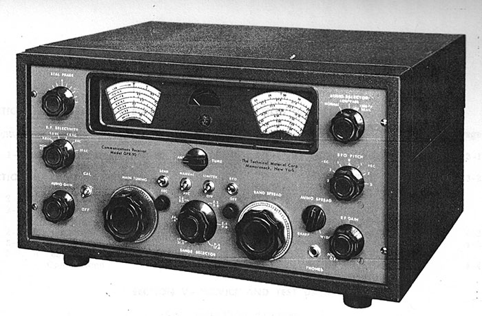
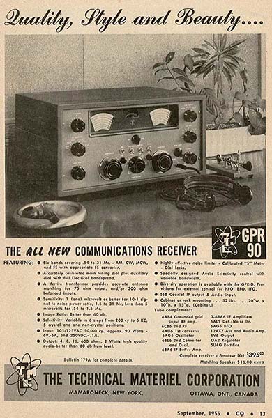
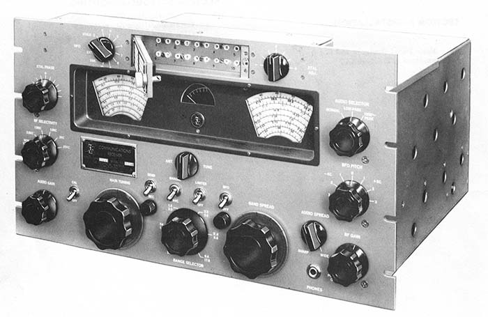
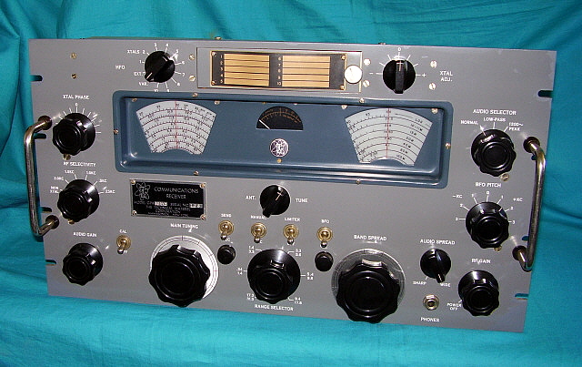
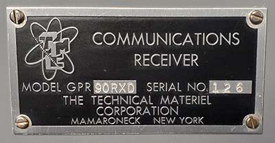
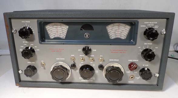
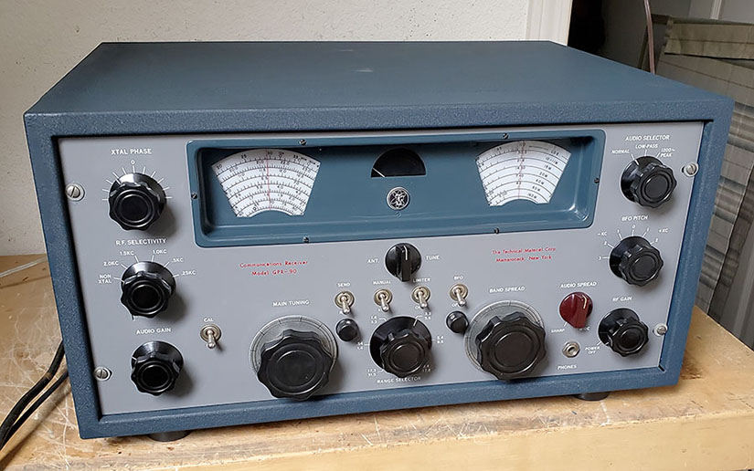
The Technical Materiel Corporation had a vast output of all types of radio-related equipment over the years. Virtually all of TMC's output was for government installations, military installations and commercial installations with most of these installations being complete stations consisting of high level, high power, HF transmitters and matching receivers with complete communications support equipment. By comparison, TMC's output of hamgear was small and consisted of the GPR-90 receiver and some of its accessories. The GPR-90 is one of those receivers that can elicit any number of conflicting reports regarding its level of performance or quality of construction from just about any collector-ham that has ever owned or operated one. Are new GPR-90 owners' expectations too high for a receiver that sold for $400 in 1955? Certainly, that's the case when the new owner expects the GPR-90 to perform and have all the features that the Collins-designed R-390A receiver had. This write-up will try to be unbiased and present just what can be "backed-up" from in-person inspections, written TMC documentation-advertising, actually reworking GPR-90 receivers and on-the-air functional testing. Also, covered is the TMC MSR-6, a SSB Adapter that is similar to TMC's well-known, military CV-591A SSB Adapter. Is the TMC GPR-90 a great communications receiver? You'll have to decide,... |
The
Technical Materiel Corporation |
|
Brief Company History
- The Technical Materiel Corporation was founded by Ray
DePasquale (aka Ray H. Pasquale) in the mid-1950s to design and build commercial and
military-grade communications equipment and installations. DePasquale had been chief engineer for Press Wireless before starting
TMC. Certainly TMC's main
business emphasis and vast output was in major communications installations that
included large, sophisticated transmitters and special purpose
receivers along with just about every type of support equipment
imaginable. TMC's customers were government users, military users and some commercial special communications businesses. Perhaps it was TMC's
advertising in QST, CQ and other radio amateur magazines that gave the impression that
ham radio was an integral part of TMC's business. Most of TMC's advertising
in the various ham magazines showed a lot of their high-priced
commercial-military equipment along side an ad for the "ham-priced" GPR-90. TMC's only product that
could be considered "for the radio amateur" was the standard GPR-90 receiver and its
accessories. The GPR-90 was
produced from 1955 up to about 1962. It was a $400 to $500 receiver that
perhaps was initially designed for use by hams and priced between the Collins 75A-4
at $695 and the National NC-183D at $385.
However, as TMC's commercial-military customer base grew, the GPR-90 wasn't to remain strictly a ham receiver for
very long (maybe it really didn't even start out as one since
it was also designated as the R-825/URR.)
|
|
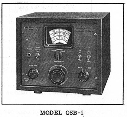
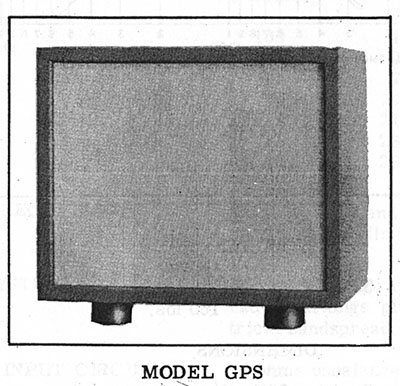
GPR-90 Accessories Model GSB-1 SSB Adapter - The GSB-1 SSB Adapter uses the 455kc IF output from the GPR-90 as its input signal. The unit has its own internal power supply and its own audio output circuitry (the earliest GSB units didn't have the built-in audio amplifier and used the Phono input on the GPR-90 for access to an Audio Amplifier grid input.) The GSB-1 uses 10 tubes and is similar in function to the TMC MSR-type or CV-591A SSB Adapter (military rack mount unit) except the GSB-1 has its own Noise Limiter circuit. It doesn't have the crystal controlled USB and LSB select. The GSB-1 had its own AVC and used a Product Detector. The dial on the GSB-1 performs the same Band Spread tuning of the IF passband that the CV-591A's Band Spread did. The cabinet and paint match the GPR-90. Model GPS Loudspeaker - There were two selections of matching loudspeaker for the GPR-90. The GPS-1 had a cabinet with an 8" depth and the GSP-2 had a cabinet depth of 15 inches. Width was 12" and height was 10" for both models. The depth of the GPS-2 matched the depth of the GPR-90 cabinet. The GPS cabinet was dark blue wrinkle and the grille cloth was cream color. The loudspeaker size isn't specified in the flyer information (where I got the B&W artwork shown) but it must have been an eight inch speaker since the height of the cabinet was ten inches. Nominal impedance was 4 ohms. |
|
The "Real" TMC Products - To say that
Technical Materiel Corporation had a VAST output of
military-commercial equipment is quite an
understatement. TMC produced almost every type of radio-related device
that could be used by the military, by the government or by commercial
users. The ham-version of the GPR-90 receiver was just a very small part of TMC's
output. Of course, one of the common critiques of the GPR-90 is that it
"wasn't up to TMC standards." But, when building for the civilian
ham market, costs have to kept reasonable, otherwise the product won't
sell. So, in reading about the GPR-90, remember,...it was only one
small facet of TMC's output and only a very limited example of their
capabilities. To get an idea of just how much radio equipment and the
different types of radio equipment that TMC produced, go to the TMC
History website,
https://www.tmchistory.org
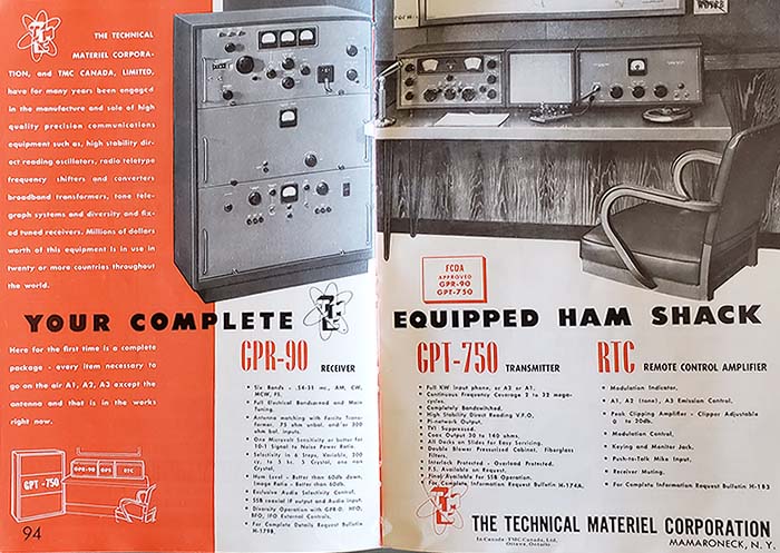
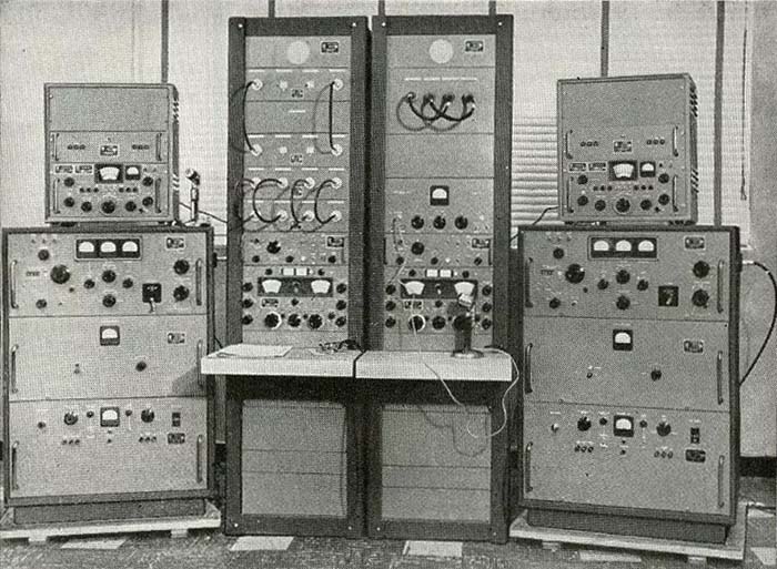
Shown to the right is a 1958 advertising photo from TMC that shows the type of equipment orders that were typical for TMC. The advertisement says that this equipment was an order that the military needed for a "critical operation" installation. In 1958, one has to wonder what that meant. The gear shown consists of two TMC GPT-750 transmitters with TMC SBE-1 SSB Exciters with A-1397 power supplies (these might be complete AN/URA-23 SSB exciters) on top of the transmitters. The two tall racks each have one GPR-90RX receiver and a TMC MSR SSB Adapter just above the receiver. In the right side rack above the MSR SSB Adapter is the RTC, a Remote Control Amp for various modes to interface with the GPT-750. Various QDP patch panels and speaker panels complete the set up. Note the two ElectroVoice 630 microphones and what appears to be a telegraph key on the operating desk of the left rack (might be a bug.) The very large GPT-750 (about the same physical size and weight as a T-368 transmitter) was capable of 1000 watts output on CW and 750 watts output on AM (about double what a T-368 could do.) It could do several other modes with various adapters or exciters that TMC sold. The GPT-750 was advertised in QST and other ham magazines during the late-fifties but the high price all but eliminated any purchases made by hams at the time. Even TMC's advertising stated that the transmitter was "too expensive" for hams and the "price" wasn't even shown in the ads. Still, it was apparent that TMC liked to keep the hams informed about what types of products they produced, even if the hams couldn't afford them (see TMC's ad from the 1956 ARRL Handbook further down this write-up.) TMC produced many other very large, high power transmitters for the military, including one that produced 100KW 2-30mc. |
|
Commercial-Military GPR-90 Variants |
GPR-90RX
- Soon after the GPR-90 was introduced, TMC realized that with a
few upgrades, it could become a communications receiver that the
military would use, especially if it was integrated into major
communications equipment installations. Knowing what the military wanted
in a variable-C tuning receiver
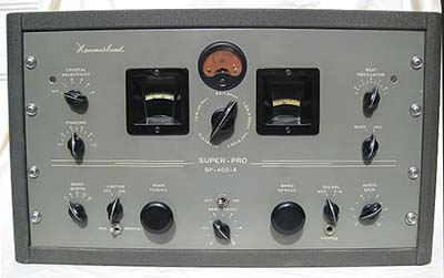
really wasn't much of a secret, it was obvious in the Hammarlund SP-600.
TMC added a similar selectable crystal oscillator that could be switched
into the HFO circuit of the receiver for added stability. Although the
SP-600 had six crystal positions, TMC decided to have ten crystal
positions available. With the GPR-90, or almost any
receiver that used variable-C tuning and wide frequency coverage per
each selected tuning range, the military was going to need the better stability
provided by a crystal-controlled HFO, especially for RTTY (the SP-600
turret band switch wasn't used due to its expense.)
This GPR-90 version
was designated GPR-90RX.
TMC used the standard GPR-90 chassis that included its unique Z-matching
transformer input and grounded-grid
broadband 1st RF amplifier and then added a ten channel selectable
crystal oscillator that was mounted to an extended-height front
panel with two wiring harnesses and an angled HFO switch for the
required connections to the receiver chassis. GPR-90RXD and GPR-91RXD - The next military market that TMC needed to supply equipment for was "diversity reception" and that required several pieces of ancillary equipment plus more modifications to the GPR-90RX. Actually, quite a number of significant changes were required throughout the GPR-90RX chassis and its circuit. The first change was to make the antenna input impedance more compatible with the types of antennas used for space diversity. The Antenna input impedance was changed by removing T1, the antenna Z-matching transformer used in the GPR-90RX, that provided selectable 300Z ohms or 75Z ohms. Then antenna input was routed to the primary windings of six, band-selected, RF transformers to provide a fixed 75 ohm antenna input impedance. The first RF amplifier circuit was changed to a standard grid-input, tuned RF amplifier rather than the grounded-grid input used in the GPR-90 (the tube was changed from 6AB4 to a 6DC6.) The secondary of each of the RF transformers was "tuned" at the 1st RF amplifier grid using the ANT TUNE control (like a preselector in later receivers.) The second TRF amplifier tube was changed from a 6CB6 to the workhorse 6BA6. Additionally, inputs for an external HFO and external BFO were provided (for master-slave operation in diversity and single HFO operation of dual receivers using the TMC VOX-5.) The receivers also had AVC and Diode Load outputs and an adjustable IF gain control (for balancing the output of multiple receivers in diversity,) all on the rear chassis apron. These receivers were designated as GPR-90RXD. The military also was using multiple channel RTTY at the time and wanted to operate as many separate RTTY channels running different information that could fit in the bandwidth available. With a wider bandwidth than the standard 7kc at -6db on the GPR-90RXD more RTTY channels could be added, so TMC provided the GPR-91RXD that featured 15kc at -6db bandwidth for up to 64 channels of RTTY and that bandwidth could also be used for up to 4 channels of independent SSB signals. |
|
|
Other GPR-90 Commercial-Military Variants
- TMC also built several types of dual diversity receivers usually
designated with a
DDR prefix followed by a number suffix. Many of these
diversity setups utilized two GPR-90RXD
receivers plus all of the ancillary equipment needed for diversity
reception. There also was a standard GPR-90 that had
some diversity capability that was designated as the
GPR-D. The 1955 ads mention that
the GPR-D had inputs for external HFO, BFO and IF Output. AVC
accessibility isn't mentioned but, if it was, then it was possible to
achieve diversity effects by just interconnecting the AVC on two
receivers and then using separated antennas for each receiver. This type
of diversity was generally only effective in the AM mode.
Interconnecting the AVC and the Diode Load between diversity receivers
with separated antennas works better and, with additional equipment,
either AM or data modes like CW, RTTY, etc., can be received in
diversity. TMC built at
least 50 different
types of complete diversity system receivers.
There also was a GPR-90R that was a slightly modified, rack mount version of the GPR-90 that had a data plate on the front panel. These rack mount GPR-90R receivers were probably installed in the various types of communications racks and consoles that TMC sold to commercial-military-government users that didn't require the more sophisticated RX and RXD versions. The military versions sometimes used specific designations with R-825/URR used for a military standard GPR-90 and with the military RX versions usually identified as R-840/URR (there's a R-840/URR shown on www.navy-radio.com that has the USN "orange" data plate on the front panel.) All R, RX and RXD versions were rack-mounted receivers. |
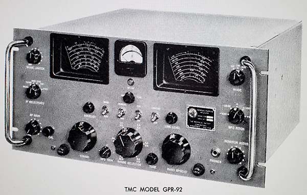
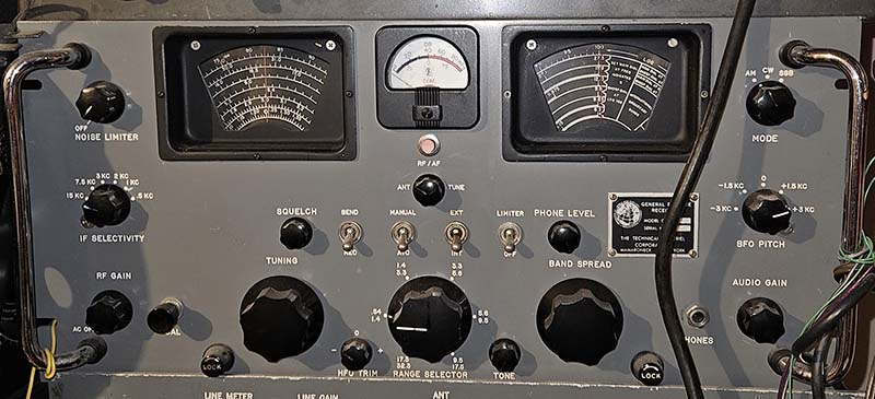
GPR-92 - In 1963, the GPR-92 was introduced. The receiver was an updated and more militarized version that had many of the GPR-91RXD features but minus the ten channel selectable crystal oscillator assembly. To allow compatibility with multi-channel RTTY or multi-channel SSB signals and with other more conventional signals, both 15kc and 7kc IF bandwidths were provided. Eighteen tubes and four solid state diodes were used in the circuit. The GPR-92 front end is very close to that used in the GPR-91RXD with the same ANT TUNE working with RF transformers in the first RF amplifier stage. The GPR-92 dual conversion scheme works exactly the same as the GPR-91RXD with a 3.500mc crystal oscillator mixing with a 3.955mc signal to provide the 455kc IF when in dual conversion. The lower three bands are single conversion and the upper three bands are dual conversion. The Squelch circuit was new and all of the audio filtering used in the proceeding receivers was removed. The meter was changed to a Carrier Level meter than combined a RF input and AF output meter with a panel push-button switch under the meter. The audio output tube was changed to a 6AQ5. The output impedances were 4, 8, 16 ohms and the 600Z output was referred to as "LINE OUTPUT." The Main Tuning dial and the Bandspread dial were changed to have a black background with white numerals and scale indexes. Two models were offered, GPR-92C mounted in a table cabinet and the GPR-92S rack mount receiver. Selling price was $920 up to $1500. Only 115 were built before the GPR-92 was discontinued. |
|
|
Other GRP Receivers GPR-10 - Late 1960s, Solid-State, digital readout, double conversion, tuned .5-32mc in 100hz steps. Priced at $3000. GPR-100 - Early-1970, Solid-State, tuned with individual thumb-wheel switches, tuned 15kc to 32mc. GPR-110 - From 1971, Solid-State, digital readout, tuned 100kc to 30mc in 100hz steps. Later TMC - TMC continued to expand in the 1960s with several companies located in many different states (Mamaroneck, New York is the headquarters location.) The GPR-92 was the last TMC receiver based on the GPR-90 design. Although there were a few later receivers designated with the prefix "GPR" they are more modern, solid-state designs. TMC continued on though providing the military with several types of transmitters and other types of communications equipment. Eventually, Neil DePasquale (Ray's son) began running the company. While all of their competition eventually went out of business or were purchased by other companies, The Technical Materiel Corporation continued on in business (although sparsely staffed) and continued to be run by Neil DePasquale. An Internet search for The Technical Materiel Corporation finds a few "hits" that indicate the company is still in business although all of the information is quite vague on details. Less than ten employees are indicated on one Internet source. The address given is still in Mamaroneck, New York (search performed 12-2024.) |
Model Designations with
Basic Identification Characteristics: GPR-90 - 6AB4 and 6CB6 RF Amplifiers, broadband untuned grounded-grid 1st RF Amplifier, dark blue wrinkle finish table cabinet, no data plate on front panel, receiver and company info in red upper and lower case semi-script GPR-90R - Rack mount version, no cabinet, top and bottom covers, otherwise same as GPR-90, has data plate on front panel showing "GPR-90R" as model type GPR-D - Has diversity mods, external HFO and BFO inputs and IF output, should have AVC output and possibly Diode Load available on rear chassis, data plate on front panel, rack mount GPR-90RX - 6AB4 and 6CB6 RF Amplifiers, broadband grounded-grid 1st RF amp, same chassis as GPR-90 but with ten channel selectable crystal oscillator assembly, extended height panel with data plate on front panel, rack mount GPR-90RXD - 6DC6 and 6BA6 RF Amplifiers, RF transformers for Ant/RF coils, ANT TUNE preselector tuning, ten channel selectable crystal oscillator assembly, variable IF GAIN control, Diode Load and AVC outputs on rear panel, remote connections on rear chassis, data plate on extended height front panel, rack mount GPR-91RXD - 6DC6 and 6BA6 RF Amplifier same as GPR-90RXD except IF bandwidth increased to 15kc for up to 64 channel RTTY and four-channel SSB, data plate on front panel, rack mount DDR - Dual diversity receivers using two GPR-90RXD or GPR-91RXD receivers or later GPR-92S receivers, some versions were in one relay rack with the two receivers and all of the ancillary equipment required for diversity reception. Larger receivers, like the DRR-5, had "double-wide" racks for all of the ancillary gear required. There were over 50 types of diversity receivers built by TMC. They generally have DDR or similar prefixes and then a specific suffix number for identification. GPR-92 - Updated and somewhat militarized GPR-90 using 18 tubes and four solid-state diodes, same front end as the GPR-91RXD, has black background dials, 15kc and 7kc IF bandwidths with a Crystal Filter with a fixed adjustment (no phasing control) on narrower bandwidths, front panel mounted Carrier Level meter with push button switch for RF/AF scaling, squelch control, tone control, fine frequency control on BFO, "C" suffix for mounted in cabinet, "S" suffix for rack mount. Only 115 built |
Detailed Circuit Description |
|
Different RF Amplifier Circuits - The RF amplifier circuits are very different when comparing the circuit used in GPR-90 and GPR-90RX receivers to the circuit used in the RXD versions of the receiver. The GPR-90/90RX had an antenna impedance-matching, ferrite core transformer T1 that allowed selecting either 75Z or 300Z input impedance. The secondary of T1 went to a network of six inductors and five capacitors that were connected together in various configurations by the selected bandswitch position to provide a broadband coupling to the 1st RF amplifier cathode on all bands. No tuning of the 1st RF amplifier was needed. The 2nd RF amplifier 6CB6 used RF transformers with the secondary tuned using the main tuning condenser and bandspread condenser with the ANT TUNE trimmer in parallel. The ANT TUNE actually performed as a f-resonance trimmer (a "fine tuning" control) for the variable-C grid input, not a true "antenna Z-matching trimmer" since Z-matching was what T1 accomplished. The ANT TUNE air variable was located inside the tuning condenser box on the GPR-90. >>> |
|
>>> The GPR-90RXD used six band-selected Antenna-RF transformers that could
only be tuned by using the ANT TUNE control. The ANT TUNE was a
small variable-C located on the rear-exterior of the condenser box. It
was
connected in parallel with the secondary of the selected Antenna coil
going to the 1st RF amplifier grid, therefore the ANT TUNE was actually "tuning" the
f-resonance of the antenna-RF coils to the 1st RF Amplifier grid input
(the ANT TUNE is used like the preselector tuning function found on
later receivers.) The 1st RF amplifier
was a 6DC6
tube. The 2nd RF
amplifier 6BA6 was a typical TRF amplifier utilizing the main tuning condenser
and bandspread condenser. With the RXD (and the RX,) the receiver's HFO was turned on when VAR
was
selected. If other positions of the HFO switch were selected, then the
receiver's HFO was turned off to allow the XTAL oscillator to function.
There also was an input provided for a completely separate external HFO
that was primarily intended for master-slave interconnection of
multiple receivers operating in diversity or for providing
"single receiver tuning" while operating in diversity. The remaining circuitry is essentially the same for all versions of the receiver,...well, a few changes for diversity operation - Single conversion is used on the lower three bands (.54mc to 5.4mc) and dual conversion on the top three bands (5.4mc to 31mc) with the first conversion at 3.995mc and the second conversion at 455kc. The conversion scheme works similar to the dual conversion circuit found in the Hammarlund SP-600 receiver. The GPR-90's dual-tuned transformers, T3 and T4, provide either a 455kc output in single conversion or a 3.995mc output in dual conversion. T2 is specifically tuned to 3.995mc and its output goes to the 2nd Conv/Osc 6BE6 where the output from the 3.500mc crystal oscillator section mixes to provide the 455kc output when dual conversion is enabled. The 455kc from T4 is routed to the input of the Buffer tube when single conversion is used and the Buffer output goes to the IF input. When dual conversion is used, the 2nd Conv/Osc tube is enabled and the 455kc output goes to the IF input. The S1A-rear bandswitch segment enables the 2nd Conv/Osc and disables the Buffer when dual conversion is used. NOTE: This conversion scheme is almost exactly like the Hammarlund SP-600 receiver right down to using the same conversion frequencies and the same crystal oscillator frequency and the use of a Buffer tube that Hammarlund called a "Gate" tube. The GPR-90 has several similarities to Hammarlund/Signal Corps SP-600 and earlier Super Pro receiver designs but the one very apparent missing design feature would be the turret band switching. It's obvious that the turret band switching would have "sky-rocketed" the price of the GPR-90 so TMC opt'd for a conventional band switching design. A crystal filter is provided at the input to the First IF amplifier followed by two more 6BA6 stages of IF amplification. RF and IF gain are controlled manually by varying the cathode resistance to chassis on the two RF amplifiers and 1st and 2nd IF amplifiers. AVC controls the grid bias on those stages when the AVC is ON. The Detector is a standard envelope type using a 6AL5 dual diode tube with the second diode used as a clipper-type Noise Limiter. The AVC uses a one section of a dual triode 12AX7 connected as a diode to provide AVC bias derived from the 3rd IF amplifier stage. The AVC is routed through two terminal strips in the RXD version for diversity applications. When operated as a "stand alone" receiver, certain jumpers must be installed on the terminal strips to route the AVC to the receiver circuitry (E1 terminals 1 and 2 need to be jumped.) Also, the Diode Load must have a jumper installed when the receiver is not used in a diversity set up. The Diversity AVC terminals shouldn't have a jumper installed. This AVC terminal was for interconnecting the AVC to the AVC on a second or third receiver for diversity operation (shielded cable required is why the ground terminal is located next to the AVC terminal.) Audio output uses a triode 1st AF amplifier (other half of the 12AX7) followed by a single 6V6 tube audio output stage. All audio coupling capacitors are .01uf values and the 6V6 cathode bias uses a 25uf electrolytic so the audio quality is definitely better than "communications grade." The AUDIO SELECTOR switch has three positions, NORMAL (no filter,) LO PASS (cuts audio highs) and 1200~PEAK (activates the AUDIO SPREAD control to adjust audio bandwidth from a flat response down to 1100hz within a range around the 1200hz peaked response - for CW or data signals mainly. AUDIO SPREAD knob was red only on GPR-90 receivers, commercial-military receivers used a black knob for this control.) >>> |
|
|
>>> The output transformer provides 4, 8,
16 and 600 Z ohm impedances and about 2 watts of audio power is
available. A PHONO input and rear chassis switch was provided to allow access to the 1st
AF amplifier (for various types of audio accessories
including some types of sideband slicers that required an audio
output stage, in fact, the first versions of the GSB-1 required
an external audio amplifier.) 15 tubes are used in the GRP-90 while 16
tubes are used in the RX and RXD versions (adding the 6AG5 Selectable Xtal Oscillator
tube.) Since that GPR-90 design is from the mid-1950s, almost all of the capacitors used in the circuitry were ceramic disks. All of the resistors were A-B JAN types. The ANT TUNE on the RXD models is a very narrow adjustment since it's actually "tuning" the Ant RF transformer secondary to the 1st RF amplifier grid. It will require FREQUENT "peaking" while tuning relatively small sections of a ham band or a shortwave band. The BFO circuit in the GPR-90 receivers used a 15pf coupling capacitor which is about average for the time period. The GPR-90RXD BFO was very lightly coupled using only a 3pf coupling capacitor to prevent "masking" of weak CW signals. With a small value BFO coupling capacitor and the standard diode detector, it was necessary to substantially reduce the RF gain control for proper signal to BFO injection ratio for either CW or SSB reception (the RF Gain has to be reduced so much that it desensitizes the receiver.) In the standard TMC GPR-90 manual in Section 7 - Single Sideband Connections - "If desired, this [BFO] injection can be raised by inserting a higher value for C59." This implies that TMC realized that the BFO injection level was too low for SSB. This recommendation IS NOT in the TMC manual for the commercial-military GPR-90RXD (probably because most of the GPR-90RXD installations already came with a TMC MSR-type SSB Adapter and the very small 3pf BFO coupling cap seems to imply that the MSRs were always used for SSB and CW reception with these receivers.) >>> |
|
>>> The SSB
ON-OFF switch on the rear chassis will ground the detector
output and allow the receiver to operate normally to the IF
output. If a MSR SSB Adapter was going to be used as a permanent
set up, then the GPR-90's detector, NL and audio sections won't
be active and the GPR-90 IF output will provide the signal to
the SSB Adapter that has all of the circuitry necessary for
complete signal processing. Using the TMC SSB Adapter vastly improved SSB reception. TMC offered a "GPR-90 matching" table-top SSB adapter, the GSB-1. It's also possible to use the rack-mounted TMC's CV-591A SSB adapter with the GPR-90 receivers. Some of the rack-mounted SSB adapters were designated as "MSR" units (Mode Selector - Receiving) and these were similar in design, appearance and use as the CV-591A that was also designated MSR-4. The GPR-90RXD manual specifies that the MSR-6 can be used for enhanced SSB reception. All of TMC's SSB Adapters use the same basic circuit, so the GSB-1 and the CV-591A perform in a similar fashion even though they don't have the same physical appearance. Any of these TMC SSB Adapters with a 455kc IF when used in conjunction with any GPR-90 model will significantly improve SSB reception. See section below on the TMC SSB Adapters for a profile on the MSR-6. |
Selecting Crystals for the
GPR-90RX or GPR-90RXD - Since the receiver is
dual conversion, two basic formulas are used. Additionally,
there is a .005% offset that is factored in to allow the XTAL
ADJ to operate around mid-scale. Fx = Crystal Frequency,
Fs = Desired Operating Frequency From .54mc to 5.6mc (single conversion) Fx = (Fs + 0.455) x 1.00005, so add 0.455mc to the desired operating frequency then multiply by 1.00005 for the crystal frequency in mc. From 5.6mc to 17.8mc (dual conversion) Fx = (Fs + 3.955) x 1.00005, so add 3.955mc to the desired operating frequency then multiply by 1.00005 for the crystal frequency in mc. From 17.8 to 31.5mc (Band 6 - doubling in HFO and High Frequency Oscillator) Fx = (Fs + 3.955)/2 x 1.00005, so add 3.955 to the desired operating frequency, divide by two, then multiply by 1.00005 for the crystal frequency in mc. If operating with the Crystal HFO, select the channel frequency desired then remember that the receiver must also be tuned to the channel frequency so that the RF and Mixer stages are in tune with the Crystal HFO operating frequency. |
|
Tubes
Used: 15 Tubes
are used in GRP-90, GPR-90R 16 tubes are used in GPR-90RX,
GPR-90RXD,
GPR-91RXD 1st RF Amplifier - 6AB4 (GPR-90, GPR-90RX) 6DC6 (GPR-90RXD) 2nd RF Amplifier - 6CB6 (GPR-90, GPR-90RX) 6BA6 (GPR-90RXD) HFO - 6AG5 Mixer - 6AU6 2nd Converter (2nd Mixer & 3.5mc Xtal Osc) - 6BE6 455kc Buffer (Gate) - 6BA6 1st IF Amplifier - 6BA6 2nd IF Amplifier - 6BA6 3rd IF Amplifier - 6BA6 Detector & Noise Limiter - 6AL5 1st AF Amplifier and AVC rectifier - 12AX7 Audio Output - 6V6GT Selectable Xtal Osc (RX/D only) - 6AG5 BFO - 6AG5 Rectifier - 5U4G Voltage Regulator - 0A2 100kc Calibration Osc - 6CB6 |
Specifications: Frequency Coverage - .54mc to 31.5mc in six tuning ranges Ant. Input Z - 300Z and 75Z selectable with GPR-90/RX, fixed 75Z in RXD Sensitivity - <1uv at 10db signal to noise ratio. Band 1 AM-BC is <5uv at 10db s/n ratio Conversion Freq - 3.955mc using 3.500mc Crystal Osc. (part of 6BE6 2nd Converter) Selectivity - Non-Xtal 7kc bandwidth, GPR-91RXD has 15kc bandwidth, bandwidth can be adjusted down to 250hz using the Crystal Filter Audio Output Power - 2 watts Audio Output Z Available - 4, 8, 16 and 600 ohms nominal impedance |
No Receiver
is Perfect |
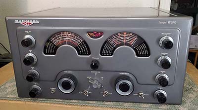
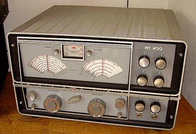
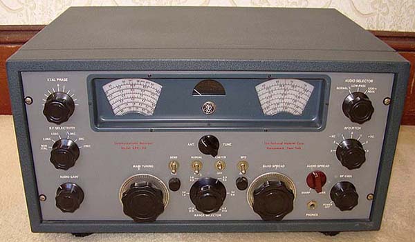
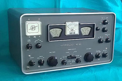
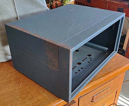
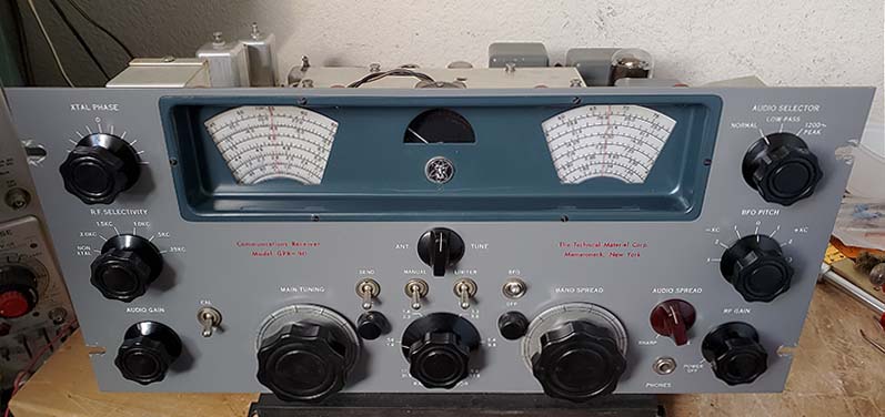
Nowadays, the GPR-90 has a varied reputation based on the many subjective reviews that abound on the Internet. It's easy to find conflicting reviews about the receiver with some users rating the GPR-90 as an excellent performer while others feel the receiver is not up to TMC quality, neither in performance nor construction. There's a tendency by many collectors to compare the GPR-90 to the Collins R-390A receiver but these two receivers are almost completely different in design and construction not to mention that the R-390A sold for almost $3000. The R-390A was and still IS a great receiver,...ultimately about 50,000 were built between 1954 and 1967. A closer Collins-comparison to the GPR-90 would be the R-388 receiver. At about $1000, the R-388 was another "to the kilocycle" accurate and drift-free Collins' front-end masterpiece of straight-cut gears, Oldham couplers, a ten-crystal multiple-f oscillator and Permeability Tuned Oscillator that produced a "to the kilocycle accurate" analog dial f-readout. BUT, other than the Collins front-end, the rest of the R-388 was pretty much a standard receiver that actually had some performance deficiencies in the AVC, detector, NL and audio circuitry (and later, the uncorrectable end-point error problem of the 70E-15 PTOs that ruined the "to the kilocycle accurate" dial readout.) The GPR-90 service bulletins warned that if a user wanted "frequency meter" accuracy then they should buy a "frequency meter" and not ask the receiver to "double" as both. Certainly a statement that revealed TMC's frustration with comparisons of the GPR-90's six band, variable-C tuning with parallel bandspread-C to any of the Collins' "to the kilocycle accurate," 30 band, PTO and multiple-crystal oscillator based tuning systems. A comparison that oddly seemed to ignore any other features of the receivers and concentrated just on tuning dial accuracy. A fair comparison of the GPR-90 would be to the Hammarlund HQ-180 receiver. Both receivers were basically contemporaries and sold for about the same price for the same intended end-users,...hams. There's even a similarity in both receiver's tuning drive systems (pinch-wheel rim-drive dials) and in their front panel layout of using two dials separated by the S-meter. Both receivers have similar performance specifications. Hammarlund even offered the HQ-180A with a selectable eleven channel crystal-controlled HFO with crystals inserted directly into sockets located on the front panel (the HQ-180AX was a similar concept to the GPR-90RX,...was Hammarlund trying for a military contract for the HQ-180?) Certainly there's no argument that the GPR-90 is a physically beautiful radio receiver creation. The dark blue wrinkle finish cabinet and the medium blue dial bezel on a gray front panel used on the GPR-90 are unique and the receiver does present itself quite well in the ham station landscape. However, if you're expecting "Collins military receiver performance" out of a $400 to $500 receiver,...well,...you'll probably be disappointed when using the GPR-90 for an actual "on the air" QSO.
|
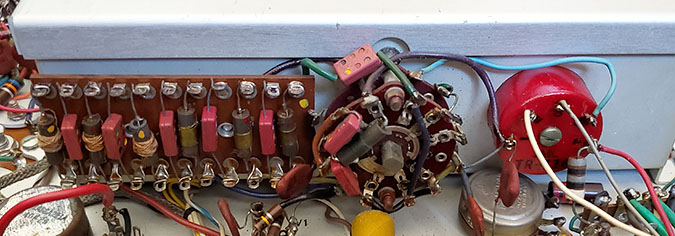
Here are some of the common complaints that I've found on the Internet. However, it's worth noting that the GPR-90 actually has more "five star" ratings than it does ratings with some negatives mentioned. Here are some of the "three star" complaints along with a couple of my own observations. 1. Dial Resolution versus Tuning Accuracy and the Whole GPR-90 Tuning Design - Although most reviewers rate the GPR-90 dial accuracy as "excellent" or "very good," it does depend on exactly what is considered "accurate." There is a difference between "accurate" and then having usable dial resolution. After alignment, most analog dial receivers will be accurate on "marker" frequencies. That would be tuning in known frequency stations such as WWV. Dial resolution allows an "accurate" receiver to tune "to the kilocycle" since the dial can resolve frequency to the accuracy of one kilocycle. The Collins 75A and 51J receivers were analog dial tuning systems that could accurately resolve "to the kilocycle." Any receiver that covers several megacycles in each of its selected tuning ranges isn't going to have a reasonable-size tuning dial that can resolve to the kilocycle. AND, add to that,...any receiver that has a Bandspread variable-C tuning in parallel with the Main Tuning variable-C tuning is going to have potential dial readout accuracy problems. And, that goes for both dials. The 100kc Calibrator found on most GPR-90 Series receivers can be used to accurately set-up the Bandspread dial but the resolution is still somewhat limited. Also, using the 100kc Calibrator, the Main Tuning dial can sometimes be accurately set-up using the Bandspread dial for a frequency-trim adjustment. But, sometimes the Main Tuning calibration reads lower than desired with the BS set to 100. In that particular condition, the BS can't be used to "trim in" the Main Tuning dial calibration (RF tracking alignment needed.) 2. The Hammarlund Super Pro Inspiration - GPR-90 tuning system uses "Pinch-Wheel" drives - The WWII Hammarlund Super Pro seems to have been the "model" that TMC chose for designing the tuning system used in the GPR-90. The dial layout versus placement of the S-meter follows the WWII Super-Pro and many of the Hammarlund HQ-models. The pinch-wheel, rim drive dial tuning system, including the dial guides, are exactly like those used in the 1935 to 1949 Hammarlund Super-Pro receivers (before the SP-600.) As to why TMC copied the WWII Super-Pro in 1955 when it was obvious then that even the "new" Hammarlund SP-600 was a "dated" design when compared to the receivers designed and produced by Collins, is a mystery. It does seem like the TMC mechanical engineers were copying designs that were already two decades old,...but, certainly the cost factor must have been an important consideration on TMC's part. Incidentally, the National NC-183D also used a pinch-wheel rim-drive tuning as did the Hammarlund HQ-180,...probably because when all of the parts are in good condition and clean, this design results in very smooth tuning and an excellent tuning ratio reduction in the drive. In fairness to the NC-183D, those are edge-illuminated Lucite dials mounted to copper-plated metal backing plates and the pinch-wheel actually works against the metal backing plate that then drives the main or bandspread tuning condensers through a gear-reduction set up,...a first class mechanical design. The Hammarlunds and TCM used the pinch-wheel to drive the rim of the plastic dial rim directly. Dial warping was a problem on the pre-WWII designs but post-WWII plastics were much better at resisting warping, so it's usually not a problem to drive the plastic rim directly on these later receivers. Although the plastic used for the dials for the GPR-90 doesn't usually discolor from excessive exposure sunlight, I did recently inspect a GPR-90R receiver that had a very noticeable tan discoloration that was limited to the portion of the dial that had been exposed to sunlight through the dial bezel opening. This discoloration was on both the main dial and the bandspread dial. It's a seldom seen problem,...but it can happen. 3. TMC's Defense Regarding Tuning Accuracy - TMC seemed to get somewhat irritated whenever the GPR-90's tuning resolution was criticized. TMC actually published testy comments in their service bulletins (SUP-1 GPR 9-56) defending the variable-C tuning with analog dials against the "to the kilocycle accurate" Collins tuning systems. The TMC arguments were, "The GPR-90 is a general coverage receiver, and a real good one, but it is NOT a frequency meter." This was followed by, "People who require frequency meters should buy frequency meters - not make them double as communications receivers." These are certainly the best known of their peevish comments that all seem to be directed precisely at TMC's "big-time" military contract competitor, Collins Radio Company. However, TMC's comments do illustrate that when comparing the GPR-90RXD to the Collins R-388 in an unbiased evaluation, maybe there's something to be considered besides tuning accuracy. TMC probably thought that really ALL the R-388 offered the end-user was essentially a frequency meter that happened to also work as a receiver. Beyond the R-388's front-end, the rest of the receiver's circuitry is standard and in some places actually deficient in performance, e.g., the detector, the AVC, the noise limiter and even the audio quality. So, maybe if the R-388 was looked at "critically" then TMC probably had a point in their "frequency meter" comparisons. Nowadays, 65+ years later, when vintage equipment from either company can be easily found, rebuilt and used, we have a different perspective on vintage receiver performance and TMC's comments advocating buying a heterodyne frequency meter to go with your GPR-90 receiver seems kind of humorous,...although I don't think it was originally intended to be. As an aside,...Beckman/Berkeley must have taken TMC's "freq meter" comments "to heart" because one of their products was an elaborate Beckman Frequency Measuring System that had a Collins 51J-4 receiver (Beckman/Berkeley Model 7700) as the main component of the instrument. 4. Cheap Construction? - This appears to be a common complaint but most reviewers are comparing the GPR-90 to other more expensive, built-for-the-military (or government) TMC products or to other expensive Collins military receivers. Hardly a fair comparison. The passive components used in the GPR-90 receivers appear to be excellent quality. Ceramic disk capacitors are used throughout the receiver circuitry. Component boards are used in a few locations to reduce chassis component congestion and to provide a better mounting platform for the circuitry. The build quality seems to be better than average if the GPR-90 is actually compared to other $400 to $500 receivers built for the ham market. That price would put the GPR-90 mid-way between a Collins 75A-4 on the high end (about $695) and a National NC-183D on the low end (about $385.) The GPR-90 sheet metal fit and finish are quite good. The GPR-90 table cabinet is gorgeous with dark blue wrinkle finish paint and a very low height compared to the usual 1950s cabinets (of course, that's an opinion, isn't it?) However, if and when a GPR-90 receiver is extensively disassembled it becomes apparent that maintenance wasn't at the forefront of the mechanical design considerations,...but then, in the commercial environment, professional repair technicians took care of the disassembly and reassembly. 5. Not Selective Enough - This is another common complaint that seems rooted in comparisons to either modern receivers or to receivers equipped with Collins mechanical filters. The GPR-90 Crystal Filter is the only control that the operator has over the bandwidth. One has to wonder if the reviewers actually adjusted the PHASING control for minimum bandwidth or just expected that the bandwidth showing on the switch nomenclature just "happened." Like any standard Crystal Filter, the GPR-90's can also eliminate heterodynes quite well but one does have to adjust the PHASING to accomplish that. The NON XTAL position will have about 7kc bandwidth at -6db. There are also a couple of audio filters that can be utilized, one for voice operations and one for CW operations. On the whole, the GPR-90 is a little better than most of its similarly priced competition for selectivity options (and at least it doesn't have a Q-multiplier for a selectivity control!) 6. Not Mechanically Stable - Another common complaint that certainly does have some merit,...but then, how many people bang on the side of their receiver just to see what happens? At any rate, there are a few things that contribute to the mechanical instability issue and that would be that the coils mount on and under the chassis directly below the tuning condensers that mount on the top of the chassis. Any flexing of the chassis will skew the tuned frequency by the mechanical movement of the LC involved. It's a common problem in ALL receivers that are variable-C tuned with L coils mounted on common chassis. When the receiver was mounted in a communications rack, there wasn't access for the operator to reach in and "flex" anything, so it's kind of a mute point when the receivers were properly installed and properly used (and there are dial locks on both dials that could be utilized.) However, mechanical instability problems that are unusual can usually be traced to the "all too common" maintenance technician practice of not installing all of the shielding and not installing all of the screws, washers and nuts. Mechanical stability did require that all of the assembly mountings were secure and tight. Leaving out screws (and even leaving out shields and covers) was a common occurrence with some types of maintenance technicians. Also, component replacement soldering problems can be a cause of instability. Wholesale capacitor replacement isn't necessary on the GPR-90 because of the ceramic disk capacitors used but the filter capacitor and a couple of the other electrolytics might have installation problems. Also, it was common to have to replace the power transformer and proper soldering with that installation would be very important. So, there are lots of ways to create your own mechanical instability problems. When in excellent condition, with minimal mechanical wear and with a competent going over of what really needs to be rebuilt or replaced, the GPR-90 is as stable as,...say,...the Hammarlund HQ-180 or the National NC-183D. 7. Demodulating SSB Signals is Difficult - A common complaint and, for a "stand alone" GPR-90, it's somewhat true but it's especially true for the GPR-90RXD receivers. The BFO coupling capacitor is 15pf in the standard GPR-90 and the GPR-90RXD uses only a 3pf capacitor. The ratio of BFO injection to signal level at the detector is about average for the time period for the standard GPR-90. However, the method of controlling RF/IF gain using the cathode resistance doesn't allow enough sensitivity control to cope with the strong SSB signals found on the ham bands nowadays. The RXD's BFO injection is very low and this low level of BFO injection may have helped with weak CW signals that might have been "masked" by higher levels of BFO injection to the detector. The low BFO injection required the operator to turn off the receiver's AVC, increase the AF Gain to a high level and reduce the RF Gain to a low level. The RXD requires a significant reduction of the RF gain to get the ratio of BFO injection to signal level correct for proper copy (so much so that overall sensitivity is reduced.) For almost all communications receivers, from the 1930s up into the early-1950s, this method of somewhat reduced RF gain was used for good CW copy. This BFO to signal level ratio also applied to demodulating the "new SSB signals" as SSB became more popular in the early-fifties. At that time most hams still had older receivers with diode detectors so to get the proper BFO ratio they reduced the RF Gain so the SSB signals would demodulate correctly. Some hams went further and increased the BFO injection by increasing the value of the BFO coupling capacitor. Later, modifications for a product detector to replace the diode detector came on the scene. The standard GPR-90 manual (in Section 7) suggests that the value of C59, the BFO coupling C, can be increased for better SSB demodulation. The standard GPR-90 is already using 15pf but certainly going up to about 45pf would help with SSB demodulation. I haven't changed the 3pf BFO cap in my GPR-90RXD because it came with its matching (same serial number) MSR-6 SSB Adapter. The MSR-6 (or any compatible TMC SSB Adapter) makes all the difference in copying SSB or CW effectively with the GPR-90RXD. The MSR provides another IF conversion (455kc to 17kc) along with a product detector and its own BFO. More details on the MSR-6 further down this article in the "TMC SSB Adapters" section. The GSB-1 SSB Adapter will also provide a tremendous improvement in SSB and CW reception capabilities for the standard GPR-90 but the GSB-1 is a rare and expensive accessory for the standard GPR-90. Connecting a temporary 30pf capacitor in parallel with C59 will provide a 45pf BFO coupling capacitance that should help with SSB demodulation until a GSB-1 is found (or one of the 455kc MSR SSB adapters.) Until either C59 is changed or a SSB adapter is found, one can use the ANT TUNE control to reduce the signal level and that will allow better demodulation of powerful SSB stations. 8. The GPR-90's Achilles' Heel - Maybe it's just me but it seems like a large number of GPR-90 receivers are either missing the Z-matching antenna input transformer or the one that's still in the receiver is defective. Unless there's some protection provided to the antenna input, any RF, even from a relatively low power transmitter, getting to the 75Z or 300Z inputs will have a direct path through a few turns of #28 magnet wire to chassis-ground. An arc inside an older style Dow-Key relay could provide sufficient RF to fry the Z-matching transformer. Many other destructive scenarios can certainly come to the imagination. Of course, TMC expected that the ham user would provide a T-R switching arrangement that not only disconnected but also grounded the GPR-90's antenna input upon transmit. But, older style DowKey relays (and most other types of coaxial antenna relays) didn't do this and many hams just ignored what could happen if the relay arced internally. What is unfortunate is that when T1 is "fried," the receiver will still seem to function okay. An inexperienced seller might even list the receiver as working fine. The problems experienced with a defective T1 are subtle in some modes of reception (AM, for instance.) In checking out a prospective GPR-90 purchase, if possible, measure the isolation between the primary and secondary windings of T1 and measure the winding's DCR to verify that it will function correctly. However, many times you won't have the opportunity to measure T1's DCR because it won't even be there but will be entirely missing. Luckily, T1 wasn't used in the GPR-90RXD versions of the receiver. However, I do have to mention that my RXD had Band 3 RF transformer's primary winding "burned open" so putting RF into a receiver's antenna input does seem to happen a lot more often than one would think. 9. Extensive Use by Commercial Users and Reworked by Hamsters - This isn't specifically mentioned on the Internet but it is implied by some of the reviews. How a receiver was used and maintained in the past can result in a litany of problems after 60+ years of existence on the Planet. Many GPR-90 Series receivers have extensive wear, especially those receivers used commercially or by the military. Many receivers were maintained by commercially employed technicians that had no regard for the equipment they were employed to maintain. Many receivers were virtually destroyed by commercial technicians with various types of rush-job, hacked repairs or non-engineered mods that were for specific needs at the time by the end-user. Many of the shields and top covers along the screws that mounted them were removed and discarded. Many of the receivers, after surviving the gauntlet of commercial technician maintenance, went on to ham ownership. That sometimes ended up with the receiver being worked on by inexperienced hamsters who lacked any ability but always seemed to be eager to modify the receiver rather than actually repair it correctly. Installing thread-cutting, sheet metal screws in place of the proper, original machine screws seems to be a common hamster solution for dealing with lost original screws. Also, hamsters always seemed eager to drill and "hack-in" a non-original receptacle rather than simply change the plug on the cable or accessory they wanted to use. So, expect to find RCA phono jacks for antenna connections, speaker connections and other circuit access points or Cinch-Jones receptacles installed just to make it difficult to "de-mod" the receiver. The upshot is not too many of the commercial GPR-90 receivers have survived in original, pristine condition. Some will be found that have been competently rebuilt, look great and function to specifications,...but many others will be non-functional, worn-out "hack jobs." To a certain extent, this has led to impetuous judgments being made on receivers that haven't been serviced in decades and certainly have corrupted circuits, worn-out components and environmental contamination ingression from poor storage conditions. The GPR-90, that is, not the RX, RXD or other commercial-military models, being that it was a ham receiver, has probably faired much better overall. Mainly because these receivers weren't subjected to the rigors of commercial-military use or those types of maintenance programs. Naturally, it depended on the ham owner,...and, after 60 to 70 years, there have probably been a lot of those. But, typically the GPR-90 will be found in better physical/cosmetic condition than any of the commercial-military variants. 10. Power Transformer Failures - This wasn't one of the Internet complaints but something I've noticed in examining many GPR-90 receivers. Most of the replacement power transformers were installed in commercial or military versions of the the GPR-90. That would be the GPR-90RX and RXD primarily, but I've also seen a replacement power transformer installed in a GRP-90R receiver. The conclusion drawn would be that since the standard GPR-90 receiver was a ham receiver it wasn't normally operated 24/7 and, therefore, if there was a component failure, it was immediately noticed and the power shut off so the power transformer never had a chance to over-heat and fail. However, the commercial-military receivers were operated long hours, perhaps 24/7. They were commonly left unattended for long time periods while still powered up. This appears to have taken a toll on the power transformers due probably to the transformer over-heating possibly from a component failure that wasn't noticed for several hours. So, inspect any "prospective-purchase" RX, RXD, R and any other GPR-90 version that was intended for commercial-military operation,...you'll probably discover that the power transformer has already been replaced (or it might still be defective.) 11. Manuals - Again, Internet reviews don't mention the TMC manuals. The GPR-90 manual just okay since not a lot of information is provided. The circuit descriptions are very basic. The installation and operational guide are fine with lots of drawings. Voltage and resistance charts are provided. Alignment information is fine. The biggest problem is that no under the chassis component identification or location is provided, not even a photograph. TMC does provide a slight hint at a component's location with a brief notation in the parts list in the column "Function & Location." For example, looking at C11 the notation is "Cathode Bypass" and "V2" for the location. I guess it's better than nothing at all. The GPR-90RXD manual is much more detailed, probably because the receiver was commercial-military in its expected use. There are several enlarged schematics that show just certain sections of the circuit that are used along with a better, more detailed circuit descriptions overall. Still, although there are photographs of the top and bottom of the chassis, none of the small individual component locations are identified. Even the "Function & Location" in the Parts List is reduced to just "Function." You're on your own to trace out the wiring versus the schematic to locate any of the individual small components. Interestingly, the CV-591A/MCR-4 manual has the components that are mounted on the numerous terminal boards identified. However, individual small components under the chassis aren't identified in this manual either. Although all of the TMC manuals are pretty good, don't expect totally complete information,...but that's typically the way most equipment manuals are anyway.
|
Reworking a TMC GPR-90RXD |
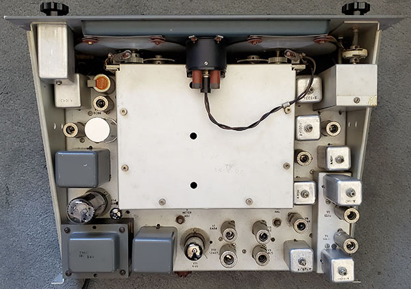
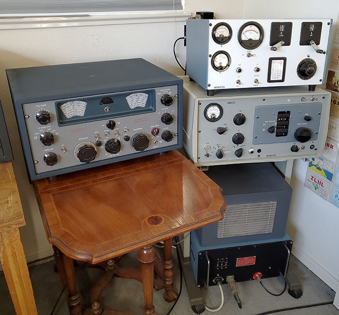
Screws, Lock Washers and Nuts with GLPT Abound - The mechanical design of the GPR-90 assembly avoids using any pem-nuts but relies almost entirely on screws, lock-washers and nuts for the assembly mountings. This results in considerable difficulty in disassembly of most of the receiver for repairs or rebuilding. Most nuts were coated with GLPT, or something similar, maybe some old type of Loc-tite, during the original assembly and that compounds the difficulty in removing most of the screws and nuts. All assemblies are mounted with screws, lock washers and nuts - there aren't any rivets used and virtually no tapped holes. There are a few clip nuts used for shield covers and some tapped holes for the front panel dial bezel mounting and, on the RXD, the data plate and crystal tag mount using screws and threaded holes. Access to many of the nuts and lock washers are limited and requires using various holding devices with bends and angles to align the lock washers and nuts with the screws. The upshot is most of the receiver is difficult to disassemble and even more so to reassemble. Mechanical Oddities - Some of the mechanical design seems to be crude or, in the case of the RXD, trying to adapt new assemblies to an existing mechanical design. The RXD mechanical operations, such as the HFO XTALS switch, seems crude with the switch coupled to another switch (HFO on-off) located down on the tuning capacitor box using an angled rod and a spring-loaded lever for actuation (it's the same function as the HFO on-off switch used on Hammarlund's SP-600.) The mounting of the external XTAL OSC box uses eight screws, all of which use lock washers and nuts on the inside of the metal box itself. These nuts are difficult to access and are mounted using GLPT (or maybe red Loc-Tite) and that compounds the difficulty of removal. Additionally the entire external XTAL OSC assembly appears to be an after-thought (it was) and contains some Rube Goldberg elements to its mechanical design and incorporation into the receiver. Front panel removal is an excruciatingly complicated ordeal due to the numerous screws, washers and nuts used for mounting, some of which are nearly impossible to access. The band switch detent assembly is mounted with two long 6-32 screws with multitudes of lock washers and nuts on each screw. Although the band switch shaft bushing is threaded, that isn't used for front panel mounting (at least on the RXD.) The band switch detent assembly is double-sprung and that results in a difficult to actuate band changing operation that sends "shockwaves" through the receiver chassis with each closure of the double springs. To complicate disassembly even more, GLPT or Loc-tite is used in many places, like the five toggle switches that all have absolutely minimal "behind the panel" clearance for a 9/16" wrench forcing one to attempt to dismount the toggle switches by removing the front dress nut. Destruction of the toggle switch dress nuts is a certainty unless heat is applied first (use a small solder iron) to the toggle switch nut and barrel to soften the Loc-tite. Front Panel Swap - My reason for front panel removal? GPR-90RXD SN:126 had extensive damage to the two bottom corners of the front panel. Some former owner used a file to "round" the corners to apparently remove whatever the damage was (the "rounding" was extensive with a radius of about 2" on each corner.) I had rebuilt the corners using J-B Weld and, fortunately, that ended up an almost undetectable repair (as can be seen in the earlier 2015 photos.) Additionally, there were some extra drilled and countersunk holes that were hidden by the tuning and band spread knobs (purpose, unknown.) A couple of years ago, I came across a nice condition GPR-90RX front panel that included a good condition Crystal Frequency plastic tag for the crystal door (the old Crystal tag I had was severely "yellowed.") Also included was an almost complete RX parts chassis. All of these items were obtained from Ham and Hi Fi in Sparks, Nevada. Swapping front panels seemed like it was going to be a quick and easy task,...but it wasn't. In addition to the numerous screws, lock-washers and nuts along with GLPT or Loc-tite, I noticed that the replacement front panel wasn't drilled for the grab handles. It wasn't difficult to drill and countersink the back of the mounting holes but it does require careful accurate measurement and marking (the mounting of these grab handles on the original panel were off from each other by .125" which doesn't sound like much but it does show a lack of skill in the old mounting. The grab handles on this new panel are accurately placed.) GPR-90RX for Parts - The GPR-90RX parts chassis is going to supply a new Antenna Coil for Band 3, 3.3mc to 5.6mc. The original coil had a burned up primary winding from some former owner allowing a transmitter output to get into the receiver's 75 ohm antenna input while on 80M (a common problem that's found on many more receivers than one would think.) Many military-type receivers will have antenna input protection in the form of a break-in relay that completely isolates and grounds the antenna input circuitry but the GPR-90RX/RXD doesn't have any antenna input protection at all. I rewound a new primary coil on the old Antenna Coil to get the receiver operational on Band 3 and it seems to function fine. But, having a good condition original coil would be better, so R&R is required. Of course, any other parts that might be usable will be available out of the parts chassis. That's what I thought until,... INTERESTING PROBLEM: I just discovered the following problem (11-24.) I thought that the "parts set" GPR-90RX would be interchangeable with the GPR-90RXD but the "RX" is quite different when compared to my RXD receiver. A little research revealed that the RX actually uses the GPR-90 chassis and adds the ten channel crystal oscillator as the only change. Consequently, the antenna coils are broadband inductors and completely different from the RXD's tuned RF transformers. So that eliminates swapping coils. Interestingly, the "RX" chassis and side panels on this "parts set" are chem-treated aluminum. The data plate was on this "RX" front panel when I got it so I know the parts set is a GPR-90RX with a serial number of 1160. Quite a bit later than my GPR-90RXD with the serial number of 126. The differences might just be the evolution of manufacturing of the GPR-90 receivers. However, as far as the Antenna RF transformer primary coil, in rechecking the job that I did in rewinding the primary coil, it looks absolutely original down to the bee's wax coating. The match to the other coils is excellent and I had a difficult time telling my coil rework from an original coil (the solder was the "give away." Fairly new solder compared to 60+ year old solder was easy to spot.) Since this rewound coil always has performed well I'm just going to leave it in place. Dealing with the Dial Guides - The design of these dial guides is exactly the same as the 1935 to 1949 Hammarlund Super-Pro receiver's dial guides. Fiber disks are mounted with spacers, screws, washers and nuts to have the complete dial guide (two of them for each dial) mount so that it's correctly spaced to keep the dials relatively close to the plastic fiducial or index piece that is also mounted by the dial guides. The operation of dial bezel removal or front panel removal requires that these Dial Guides be disassembled so the dials themselves aren't damaged. The nut is removed, then the lock washer and the flat washer. Then the first fiber disk can be removed. This operation has to be performed on the remaining three Dial Guides also. Next the S-meter is disconnected. Then the dial bezel can be dismounted after the six mounting screws are removed. This operation is easy with the GPR-90 (out of the cabinet) but the RXD version has the XTAL OSC chassis mounted directly over the Dial Guides. Dismounting the XTAL OSC chassis is difficult due to the HFO on/off switch linkage and the cabling to the XTAL OSC chassis. It's much easier to work underneath the XTAL OSC chassis using your fingers to slip on the disks, washers, lock washers and to thread on the nut. Sometimes it helps to secure the screw head with a piece of tape on the bezel front side. Also, using a small piece of tape wrapped on the screw end while the disk, washers and nuts are off will help keep the remaining Dial Guide pieces in place. The entire operation of dealing with the Dial Guides requires patience and some dexterity.
Rack Mount Panel Thickness versus Control Hub Threads - The rack mount panel used on the RXD and other TMC rack mounted receivers is 0.190" thick aluminum while the front panel used on the standard GPR-90 is 0.125" aluminum. This slight increase in the panel thickness results in all of the controls that must be mounted to the front panel barely have just enough threads showing through the panel to have the mounting nut thread on. Only the thinnest of lock washers can be used on the RF and AF Gain controls. Luckily, only the RF and AF gain controls and the PHONES jack use mounting nuts,...but wait,...there's the AUDIO SELECTOR switch also,... AUDIO SELECTOR switch problems - This entire assembly mounts too close to the rim of the Bandspread dial. During reassembly the position of the assembly has to be carefully tightened making sure the shield can isn't in a position that allows the BS dial to rub against it. Once I had the assembly oriented so it wouldn't be rubbed against by the BS dial, then I found I couldn't thread the mounting nut onto the hub because of the increased rack mount panel thickness combined with the .060" thick aluminum side panel "wrap around" that the assembly switch hub mounts through. I tried various shortcuts to fix the problem but none of them worked. I had to entirely disassemble the switch itself to extract the detent-hub piece. This allowed me to remove about .060" from the length of the shoulder at the base of the hub which would then have more threads project out the front of the panel and allow threading the mounting nut on. The switch was reassembled and then the shield piece was slipped over the switch (the rear part of the switch that has the toroid coil has a threaded stud that must project through the back of the shield can and have a 6-32 nut and washer installed) and then the entire assembly mounted to the front panel and placed so it doesn't have the BS dial rubbing against it. This assembly did fit the former front panel because the front panel had been counter-bored to have the mounting nut set deeper into the front panel material (what a hack-job! I actually think constant wear from trying to get the nut to thread onto the threaded hub finally wore the front panel relief, not actual counter-boring.) Front Panel Touch-up - The RX panel had its share of scratches and missing paint. Nothing serious, just the normal wear on a commercially-used receiver panel. I used Testor's Model Paint that comes in the small glass jars in a large variety of colors. Large selections are available at Michael's or Hobby Lobby. I used gray mixed with a little white and a little yellow to get close. When matching color and using almost any type of paint, you have to have good natural light first. Then you have to mix the match to be a shade lighter than the panel paint. Most paints will dry to a slightly darker color so mix the match to a lighter shade when the paint is wet. Paint a rack notch to see how the color match dries. If you've mixed it light enough it should dry to the correct panel color. Even at that, my match had a slight blue hue that must have been in the gray base paint I used. It's a barely noticeable mismatch when in high level natural light and a near-perfect match in normal room illumination. See 2024 photo in the "Conclusion" section below. Daka-Ware Knobs - One "NOTE" on the six Daka-Ware knobs used for the Audio Gain, RF Gain, BFO, Audio Selector, Xtal Phase and RF Selectivity,...each knob is actually a medium-size Daka-Ware knob combined with the small-size Daka-Ware skirt. If a GPR-90 receiver has one of these knobs is missing, it takes two different sizes of Daka-Ware knobs to make the TMC version. Alignment Difference for the RXD Models - Antenna/1st RF transformers have an adjustable slug but there's no information on how to align these six coils. Since each secondary of these RF transformers works in parallel with the ANT TUNE control, the adjustment slug sets the proper inductance to provide a tuning range that works from full mesh to un-meshed for ANT TUNE in conjunction with the lowest tuned frequency on the selected band (ANT TUNE around full mesh) to the highest tuned frequency on the selected band (ANT TUNE un-meshed.) Unless someone has been into the receiver and changed these adjustments, just a check of the function of the ANT TUNE on each band at the low end and the upper end of the tuning range will probably show that the inductance is set correctly. If not, set the slug adjustment to provide the correct range of tuning for the ANT TUNE air variable for each band. Alignment of GPR-90 - The GPR-90 manual's alignment procedure is fairly detailed with good drawings for adjustment locations. There's one error in the .56mc Mixer alignment where L2 is specified and it should be L7. But, it's a pretty obvious error if you've done alignments before. The IF alignment is pretty standard with referencing the 455kc crystal in the Crystal Filter for the exact IF that should be used. The 3.955mc conversion and the 3.500mc crystal oscillator trim are covered in detail. An oscilloscope is called out for adjusting the HUM BALANCE control, although an AC volt meter is also mentioned. Overall, the alignment procedure is easy to follow and shouldn't present any problems to attaining the best response from the GPR-90. Be sure that all of the tubes are tested and all test like NOS tubes or that they are NOS tubes. |
The Technical Materiel Corp. - The MSR-6 SSB Adapter |
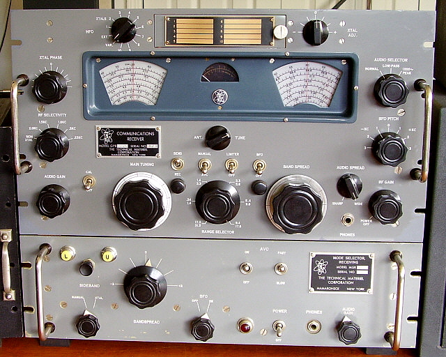
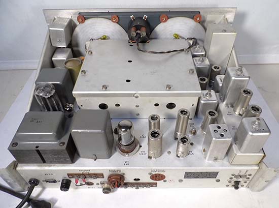
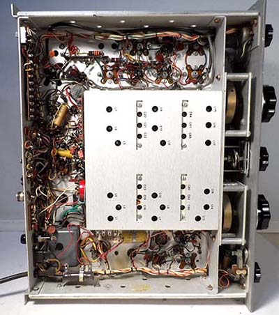
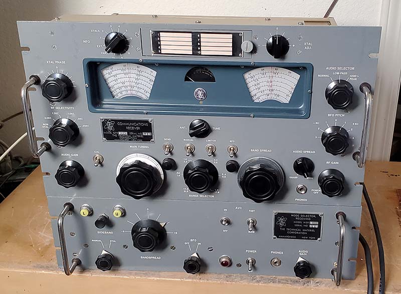
This early RXD has all of the chassis aluminum iridite-treated (aka anoline) resulting in a gold color. The side panels and shield covers are also iridite-treated. Grab handles usually weren't installed but these are the type that TMC used on other equipment. Note the J-B Weld repairs to bottom corners of the RXD panel. Also, note the severely "yellowed" Crystal Frequency plastic chart. Included with this RXD was the matching MSR-6 SSB Adapter. |
The Technical Materiel Corporation designed and built several
variations of their popular CV-591 SSB Adapter that were designated as "MSR"
or Mode Selector-Receiving. These adapters were compatible with
many types of receivers used by the military and commercial users. The
receiver used had to provide an IF output that was then connected to the
input of the SSB adapter. TMC supplied SSB adapters for the popular IFs
used in the 1950s and 60s (455kc, 500kc and 200kc.) TMC offered the CV-591A and CV-657A (and many other variants)
for the military. The CV-591A utilized 455kc IF input while the
CV-657A utilized 200kc. The military-commercial MSR series went from MSR-1 thru
MSR-9. MSR-3 utilized 200kc IF input while the MSR-8 utilized
500kc IF input. All other MSR numbers utilized 455kc IF input.
The CV-591 and CV-591A units are sometimes referenced as MSR-1
and MSR-4 in some of the TMC documentation. Generally, the MSR
designation was used if the SSB Adapter wasn't part of a
specific military contract. CV designation is just for military
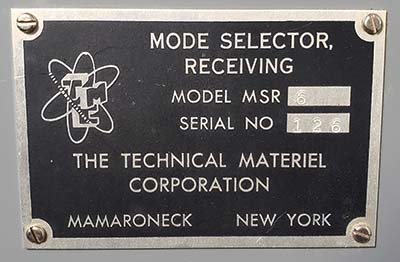
contract SSB Adapters. Shown in the photo to the left is the GPR-90RXD set-up with the TMC MSR-6 Mode Selector - Receiving SSB Adapter. Both the receiver and the adapter are assigned the same serial number (126) which implies that they were sold, installed and used together as a "set" (although originally "rack mounted.") Circuit Description - All of the TMC SSB adapters work in a similar manner. The adapter circuitry down-converted the incoming IF signal from the receiver, 455kc for example, to a lower frequency of 17kc and then mixed a BFO to provide product detection. Bandpass and Low Pass LC filters were utilized to increase selectivity. A crystal-controlled oscillator was used for the first conversion (receiver IF to 17kc) and also a VFO called "bandspread" (manual select) was provided. The two crystal frequencies are 17kc above and below the IF to provide selectable Upper or Lower sideband (if these two crystals are missing, which they sometimes are, finding new replacement crystals nowadays, in 2024, is impossible. You'll have to just use the MANUAL-BANDSPREAD for tuning. If you're patient, used crystals of the correct frequency can be found.) Sideband selection used a front panel push-button that actuated a selector relay that selected the proper crystal and also operated the "U" and "L" lamps accordingly. The AVC circuit operated on the incoming signal from the receiver and provided a fairly constant level of signal and had selectable fast and slow AVC action. There wasn't a Noise Limiter circuit in the military adapters as there was in the GSB-1. Audio output provided was 8.0Z ohms or 600Z ohms from a single 6AQ5 tube. Although specifically for SSB reception, CW signals could also be received. Also FSK could be received. Additionally, the ability to select the upper or lower sideband of an AM signal or to receive an AM signal in the "exalted-carrier" mode (AM + zero-beated BFO) was available. Exalted carrier reception usually improves weak, difficult to copy AM signals. There were several remote operation options available including remote sideband selection or detection which used a Tone Oscillator circuit for remote identification of which sideband was selected. Also, the BFO could be operated and tuned remotely. Some versions were specifically designed to utilize remote inputs from specific TMC-built receivers. Ten tubes were used in the MSR-6 and in all of the TMC SSB Adapters. |
MSR-6 Hook-up to GPR-90RXD - Once connected to the particular receiver, if only the SSB
converter audio output is utilized then the user will not have
the availability of the receiver's circuitry down-stream from
the last IF stage, usually the noise limiter and the receiver's
audio output circuitry. Two separate speakers can be used with
one connected to the standard receiver audio output and another
speaker connected to the SSB adaptor's audio output. With the
dual speaker set-up, the user can choose the receiver's audio output for
AM signals (probably better fidelity) or the SSB
adaptor's output for SSB or CW signals (virtually
distortion-free SSB.) Single speaker operation can be achieved
by paralleling the adapter's 600Z output with the receiver's
600Z output (Z is then 300 ohms at either the receiver or the
adapter.) Then connect a 4.0Z ohm speaker
to the receiver's 8.0Z ohm tap (or to the adapter's 8.0Z tap.) Since now the
total secondary impedance is 300Z, using either of the 8Z outputs
will now provide a 4Z match for a 4Z speaker. By turning down the AF Gain on the
unused receiver audio section or the unused SSB adapter, only the
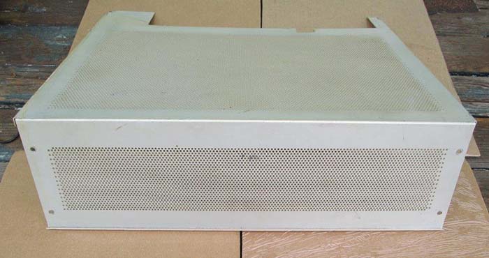
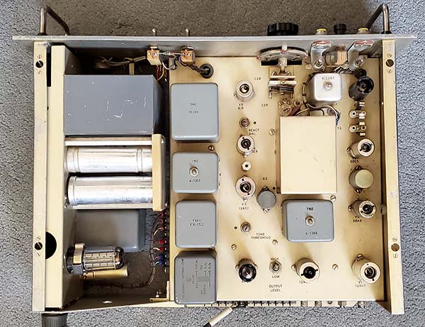
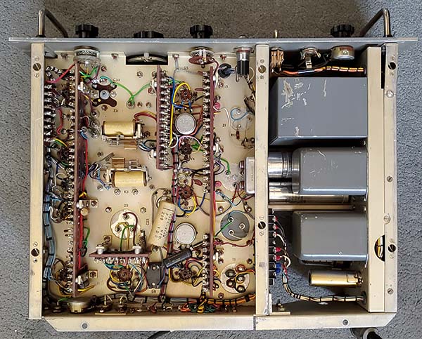
desired audio comes through the loudspeaker. MSR-6 Check-out - It's been about nine years since I've applied power to this SSB Adapter. I did some repairs to it in 2015 that got it functional but I wouldn't call that work a restoration,...just a repair. So, it's been in storage for awhile now. After retrieving it out of the shop, I looked it over and saw that there wasn't a power connector used. Small push-on terminals with heat shrink insulation provided the connections for the power cable (did I do that?) Also, very obvious (and, of course, I definitely remembered this,) the top and bottom covers were missing. Additionally, the USB and LSB crystals were missing. Getting special order crystals is a thing of the past. Nobody will produce a single, special grind crystal for anyone, anymore (it was difficult and expensive to get any special ground crystal at a frequency below 1.000mc 15 years ago when International Crystal was still in business.) The frequency needed would be 17.0kc above and below the receiver IF and since the MCR-6 is a 455kc unit, 472.0kc and 438.0kc crystals would be required. Luckily, the MSR-6 can be operated in MANUAL and that requires that the BANDSPREAD control be tuned for the SSB signal. Basic MANUAL tuning required the correct USB or LSB be selected, then set the BANDSPREAD to +2kc for USB or -2kc for LSB and then tune the receiver for best SSB demodulation. I looked through my box of mil connectors and found a three pin that would fit. It was easy to wire the power cord to the new connector. Somewhere along the line, I had removed the 5Y3GT rectifier, so I had to install another one from the tube stock. When AC power was applied there was a loud buzzing that sounded like a relay. This only lasts a few seconds and then the relay latches. I had to work with the sideband selector switch. It didn't always actuate the K3, the sideband selector relay. I sprayed some DeOxit down the barrel and worked the switch which loosened it up allowing it to now switch sidebands whenever it was pressed. I connected a 600Z speaker to the proper terminals and connected a shielded cable from the MSR IF INPUT to the GPR-90RXD IF OUTPUT. Too bad that the receiver uses a RCA phono jack and the MSR-6 uses a BNC but a RCA to BNC adapter solved that problem. |
|
|
Operating the MSR-6 with the GPR-90RXD - The GPR-90RXD receiver is providing the signal to the MSR-6 at the IF output. However, the detector, AVC and audio circuits are still functional and, if a loudspeaker is connected to the GPR-90RXD, that signal will be heard. But, the audio from the MSR-6 will also be heard. The BFO on the RXD doesn't need to be turned on. Since the distortion that is normally heard from the RXD when receiving SSB is due to the receiver's diode detector and anemic BFO circuits, it's actually possible to significantly increase the RF Gain when receiving SSB through the MSR (like to maximum.) Also, the RXD AVC can be used to prevent blocking from very strong signals but the MSR also has its own AVC and its own BFO (so turn OFF the receiver's BFO when using the MSR.) Even though I have to use the MSR BANDSPREAD for tuning SSB signal into the passband, I have to also make sure that the proper USB or LSB is selected. This requires that the sideband select relay operate to alternately select USB or LSB. Pushing the actuator button causes the sideband relay to switch. Once the proper sideband has been selected, then tuning in a SSB signal is just a matter of tuning the RXD until a SSB signal is heard. The manual says that the receiver should be set 2kc above the SSB USB signal's frequency and the MSR BANDSPREAD set to + 2kc, then tuning in an USB signal on the receiver should demodulate correctly. Since the RXD RF Gain can be advanced quite a bit (all the way to max is okay,) there will seem to be much better sensitivity or response to SSB and CW signals now. When switching to 40M or 80M, LSB will typically be used and the sideband selector button should be pushed to have the relay switch to LSB. Then tune in SSB signals in the same manner as with USB except BANDSPREAD will be on the -2kc side. When receiving CW, the Crystal Filter on the GPR-90RXD can be used to greatly enhance CW reception by narrowing the passband. This works extremely well for CW reception since the MSR provides a Product Detector and the receiver RF Gain can be left at maximum. |
Getting the Crystal
Oscillator Working - The Missing Crystals Solution
- Although it's next to impossible to have brand new, custom-ground
crystals made nowadays,...at least for crystals made in the USA,...there
are many used or even new (NOS) quartz crystals available that are already
made, that is, they aren't a custom-ground crystal, they just happen to
be the frequency needed. Looking on eBay, I was able to find a 440kc
crystal in a HC-33 package (like the originals.) That crystal would be
2kc high. For the 472kc, the closest I could find was 480kc or about 8kc
high. This crystal was also in a HC-33 package. With both crystals
having a somewhat higher active frequency than needed, the "plan" is to
parallel a small capacitor on the crystal socket terminals (under the
chassis) and bring down the frequency of the oscillator for each
crystal. I'm pretty sure the 440kc will pull down to 438kc. I'm not so
sure about pulling the 480kc down to 472kc,...experimentation required. To my surprise, when I plugged in the 440kc crystal into the Y1 socket, set the MSR to "LSB" and "XTAL" then tuned in some SSB signals on 40M they demodulated perfectly. I then installed the 480kc into the Y2 socket, switched to "USB" then tuned in some SSB signals on 20M and to my real surprise they demodulated perfectly. Hmmm. In reading the MSR manual, it's apparent that 472kc and 438kc weren't "hard and fast" frequencies for the two crystals. The manual says that to place the SSB signal within the "center" of the passband, 472kc and 438kc were the crystals used but, if it was desired to skew the SSB signal to another part of the passband then different crystal frequencies could be used. It's like tuning in a SSB signal in relation to where the BFO is set on a receiver, there's no real "correct" frequency setting for the BFO (other than as a sideband selector, that is, either above or below the 455kc IF) and the actual BFO frequency is a matter of preference for how the SSB signals sound when demodulated. Both of these crystals were intended for a "solder in" installation so the pins were actually long 22ga. slightly hardened wire leads. I had to cut the wire fairly short and put a tight "bend" on the ends to have the wire fit tightly into the socket receptacles. Once installed, I powered-up the MSR and actually measured the crystal oscillator frequency. LSB was 440.1kc and USB was 480.0kc so this verified that the crystal oscillator was running at the specified crystal frequency. Back to referencing the manual, the crystal frequencies aren't exactly critical and being off a couple of KC can be compensated for with the receiver tuning. The upshot is, this "fix" was much easier than anticipated. |
|
|
|
Top and Bottom Covers - Covers for the top and bottom aren't difficult to make although if they are made to be exact duplicates of the originals then some difficult bends would be necessary for the bottom cover. The top and bottom covers are held in place with D-ZUS fasteners. When these top and bottom covers were lost, so were the D-ZUS heads. I never bothered making the covers because so much of the MSR-6 seemed to be missing. In looking at the photos of the MSR-6, the bent sheet metal sides and back can be seen. I've tried to straighten these problems but there's not enough support with the bottom cover missing. The weight of the power supply chassis and rough handling has caused the sheet metal crack at one of the mounting holes for the power supply. If I do make the covers, D-ZUS fasteners are easily available off of eBay. The top cover had the same perforated metal venting as the GPR-90RXD top cover. The entire top cover could be made of perf metal to make it easier to replicate. The bottom cover could be made of solid .060" aluminum that's screwed to the bottom of the side rails for better support of the entire chassis. |
Performance -
Here are some of the advantages of using the MSR-6 with the GPR-90RXD
for SSB reception. 1. Improved SSB and CW Reception - GPR-90RXD RF Gain can be set to maximum with the AVC on and there's no distortion on SSB or CW. The major disadvantage of using the GPR-90RXD as a "stand alone" receiver for SSB or CW is the very lightly coupled BFO. This weak BFO injection requires that the RF Gain be substantially reduced and the AF Gain advanced for both SSB and CW reception (AVC turned off.) In most receivers, that is, those with a little more BFO injection, the RF Gain only has to be reduced moderately so sensitivity isn't impacted too much. The standard GPR-90 has a 15pf BFO coupling cap but the manual mentions increasing the value of C59 for better SSB reception but that suggestion isn't in the GPR-90RXD manual (probably because most of the commercial-military installations included a MSR-type SSB Adapter.) Another consideration is that using the MSR-6 provides another IF conversion (455kc to 17kc) and a product detector, so it's obviously the best choice. This also applies to the GPR-90 when used with the GSB-1 SSB adapter. 2. Two Separate AVC Circuits - When using the MSR-6, the GPR-90RXD is running at maximum sensitivity but controlled by its AVC to prevent overloading. I've tried it both ways, receiver AVC off or AVC on,...not much difference, except you get the S-meter function when the receiver's AVC is on. I left the AVC on the MSR-6 turned on also since it works internally with the its own circuit to control the 455kc IF signal level at the grid of the MSR's Input Amplifier. 3. S-meter Works for SSB and CW - S-meter functions for SSB signals if the GPR-90RXD AVC is turned on. This actually works very well and seems to be fairly believable for signal levels involved. 4. Only One 4Z Loudspeaker Required - Only one loudspeaker is required. Jump Audio Output 0 on the RXD to terminal 5 on the MSR, then connect another jump from Audio Output 600Z on the RXD to terminal 6 on the MSR. Then connect a 4Z loudspeaker to 0 and 8Z on the RXD. Adjust the AF Gain to minimum on the RXD if using MSR-6 audio output. Or, reduce the AF Gain to minimum on the MSR-6 if using the RXD in AM mode. This allows the best performance in SSB/CW or in AM reception (this setup is really convenient and works quite well. As an additional note, really only the wire from RXD 600Z to pin 6 on the MSR is necessary because the GPR-90RXD and the MSR-6 are mutually grounded by the IF input/output coax making the wire from terminal 0-gnd to terminal 5-gnd redundant,...but sometimes redundant grounds are good.) 5. Use the GPR-90RXD Crystal Filter for CW Selectivity - Using the MSR-6 for CW reception is a real benefit that turns the GPR-90RXD into an excellent CW receiver. For CW reception going through the MSR-6 using the GPR-90RXD's RF SELECTIVITY, the Crystal Filter, can be switched in for reducing the receiver's 455kc bandwidth for additional selectivity. This is almost mandatory for CW reception, otherwise the bandwidth is too wide. 6. Multiple Types of AM Reception with the MSR - You can receive AM through the MSR-6 by turning off the BFO. But, remember, it will be one sideband plus carrier and the bandwidth will be about 3kc. You can tune in the AM signal on the receiver and then use the MSR-6 sideband select push button for the desired sideband and fine tune the receiver for best audio. If the MSR is in MANUAL, the BANDSPREAD can be used to fine tune the MSR. It's also possible to receive single sideband AM through the MSR-6 with its BFO on to provide exalted-carrier AM reception. Exalted-carrier will help when trying to copy very weak AM signals. With a lot of QRM, it's possible to switch between USB and LSB on the MSR-6 when listening to an AM signal to receive whichever sideband has the least interference. It takes a little experimenting with the different methods of AM reception since the MSR bandwidth is narrow and only the sideband that is selected can be easily tuned. However, if you prefer regular DSB AM, then use the GPR-90RXD audio output by turning up its AUDIO GAIN control and turning down the MSR-6 AUDIO GAIN control. Now the loudspeaker is being driven by the GPR-90RXD's circuitry from its detector on through its audio output stages. In this set-up, the GPR-90RXD's IF passband is about 7kc and its NL and the AUDIO SELECTOR can be used and its Audio Amplifier stages are driving the loudspeaker. 7. GPR-90RXD/MSR-6 Performance Wrap-up - The combination of the GPR-90RXD and the MSR-6 is impressive. The MSR-6 actually transforms the RXD from a receiver that can barely cope with SSB or CW signals into a receiver that is easy to use on SSB and provides top-notch signal response as well. The use of the RXD Crystal Filter in combination with the MSR-6 when operating CW gives the user a very selective CW receiver that also has the full sensitivity available. By just manipulating the two Audio Gain controls, the MSR's or the RXD's, the user can switch over to DSB AM reception with the excellent audio capabilities of the GPR-90RXD. It almost seems that without a TMC SSB Adapter, the GPR-90RXD performance would probably disappoint the user,...unless AM signals were all the user was interested in receiving. The TMC SSB Adapters will expand the capabilities of the GPR-90RXD and the combo's performance improvements are very apparent. |
The Technical
Materiel Corporation - GPR-90
SN:1893 |
The standard GPR-90 is quite a different receiver from
the military-commercial GPR-90RXD profiled above. Of course, the selectable crystal
oscillator and the extended front panel found on the RXD are the most obvious
external differences, but internally, there are many differences in
front end circuit design. For example, the antenna
input and first RF amplifier are unique to the GPR-90. First, there's
the dual impedance antenna matching ferrite core transformer that
allowed either 75Z or 300Z, balanced or unbalanced line antenna inputs. Then,
the output of the Z-matching transformer went to a network of six
inductors and five capacitors that were connected together in various
configurations by way of the
selected bandswitch position to provide a broadband coupling to the
grounded-grid 1st RF amplifier cathode on all bands. No tuning of the 1st RF amplifier was
needed. The Ant Tune of the GPR-90
is an air trimmer capacitor connected in parallel with the 2nd RF
amplifier grid tuning and only acts as a "fine tuning" for the main tuning condenser and the bandspread
condenser. Quite unlike the RXD's Ant Tune that's an actual "preselector
tune" working with selected RF transformer secondary windings
that were then tuned for the first RF amplifier grid input. Essentially,
the GPR-90 and the GPR-90RXD have completely different front ends but the rest of the GPR-90 receiver
circuits are about the same as the RXD's (with the exception of the diversity additions used in the RXD.) So, this profile will be of a recently purchased GPR-90 receiver of a rather late vintage. The serial number is fairly high at 1893. The chassis sheet metal and the side panels are chem-treated, natural color aluminum. The GPR-90 receiver I had in 2008 was an early version without the 100kc Crystal Calibrator and its chassis and side panels were gold iridite-treated aluminum. Sometime around 1957, TMC must have gone to chem-treating the aluminum sheet metal (this can't be anodizing since that results in an electrically non-conductive aluminum oxide surface.) This GPR-90, being a late version, does have the 100kc Crystal Calibrator. Another oddity is the SO-239 coax receptacle for the antenna input that almost appears to be original. It has a stenciled "ANTENNA 75Z" by it and it is in parallel with the 75Z input on the terminal strip (if it wasn't for the stenciled "ANTENNA" I'd think this was a hamster addition since the quality of the installation doesn't appear to be all that professional. It's possible that the original 75Z coax receptacle was a BNC-type that was replaced with the larger SO-239. That's why the stenciling is present but the receptacle fit is poor and some of the stenciling is covered by the SO-239 flange.) |
|
|
|
|
The GPR-90 arrived on Jan 2, 2025. It was put on the bench on Jan 4, 2024.
1. Cabinet has Too Little Feet - Cabinet is very heavy, probably around 25 pounds. Removed chassis from cabinet and placed chassis on workbench. Cabinet rubber feet are too small. These are non-original replacements. Looking at the shadows of where the original feet were up against the paint on the bottom of the cabinet, it looks like the original diameter was 1.25" to 1.5" - Looking at photos of original feet and extrapolating the apparent height, it looks like the height was 1.0" to 1.25" - I ordered 1.5"D x 1.0"H rubber feet for the cabinet. Cabinet is going to require some paint touch up all over. Probably a matched color-wash will correct the paint issues. 2. New Replacement Electrolytic Capacitors - Filter capacitor looks original but is a three section can type with 40-40-20uf all 500wvdc values, but the 20uf section isn't connected to anything. CDE brand with a cardboard cover. The other two axial mount electrolytics appear to be original. The filter cap tests okay but the single 20uf 250vdc electrolytic is open. I didn't check the 6V6 cathode bias electrolytic but it's the original one. I have new replacements for all of the electrolytic caps including a new CE replacement multi-section can 40uf-40uf. Although this GPR-90 looked very original from the photographs, it had several modifications that were well-camouflaged and not obvious. The following sections 3, 4, 5 and 6 detail the mods and the removal process to return to original. 3. Sand-cast B+ Dropping Resistor Replacement for R87,...an unsoldered installation - Two 10K 10W WW sand-cast resistors in parallel to act as a B+ dropping resistor for the 0A2 +150vdc regulator. This installation was the worst of "hamster" rework with the connection of the resistor to the 0A2 B+ pin not even soldered. Wonder how much noise and instability that caused? I salvaged an original R-87 from the GPR-90RX "parts set" and installed it in the original location using its original insulation pads and hardware. The original wires from the harness were in good condition so the hook-up to the original R87 was easy. The entire +150vdc regulated supply had to be rebuilt as described in the next section (4.) 4. A Second Voltage Regulator? Really? - Another non-original mod was to add a second 0A2 regulator tube for an additional regulated +150vdc circuit that was exclusively connected just to the Accessory socket. A second B+ dropping resistor was added, a 5K 25W voltage divider type of WW resistor adjusted to 3.7K. The resistor was connected by wires to pin 8 of the Accessory socket for the +250vdc B+ source and then the other end of the resistor was connected by wires to pin 7 of the 0A2 and pin 7 of the Accessory socket for the regulated +150vdc. The additional 0A2 regulator was obviously for some external accessory. But, when the accessory was in operation, both +150vdc regulated voltage circuits were loading down the +250vdc B+ line (not a lot since the two B+ dropping resistors were fairly high values.) This second +150vdc line may have been a mod-solution that was installed after the failure of R-87 and that failure might have resulted from excessive current drawn on the single original regulated +150vdc line when operating the external accessory (whatever that was.) All of this mod of adding the second 0A2 regulator is unnecessary since I don't intend to run any accessories with the GPR-90 (except for an original GSB-1 SSB Adapter, the only accessory that I'd use if I had one and it has its own internal power supply.) Removal of the non-original 5K 25W voltage divider resistor with the wiring to pin 7 and 8 of the accessory socket and the connection to pin 7 of the second 0A2 socket was necessary to have the circuitry returned to original. Of course, one has to ask, why would someone modify a $400-$500 receiver when the needed voltage regulation could have been added to the $100 accessory? Removal of the tube socket might require the installation of a Cinch plug cover (unfortunate result of mod installation-destruction.) In thinking this over, a Cinch plug would allow the socket screw mounting holes to show. I can use epoxy to fill the screw holes, paint the epoxy silver after it cures and then install a flat-type Cinch plug. 5. Accessory Socket Mayhem - The Accessory socket had several added wires that were just "tack soldered" to the socket pins. Three of the wires were routed out the key hole of the socket (these had been cut flush on the exterior of the socket.) These cut wires were removed. An 18ga. TC jumper had been added between pin 3 and 4. This wasn't original and actually grounded to chassis one end of the tube filament voltage line which then eliminates the "hum balance" pot from the circuit. The idea of the hum balance is to provide a CT to ground external from the transformer winding that is then adjustable for the least amount of hum. I suspect this jumper was added for compatibility for the tube filament wiring of the external accessory used. I removed the jumper to have the hum balance work correctly. I removed a .005uf capacitor to ground off of the 600Z terminal. This was probably added to prevent RF from getting into an external device that was operating off of the 600Z line (like a ham-type audio RTTY TU.) 6. Cheap Broadcast Radio Junk Box Third IF Transformer - T8, the 3rd IF to Detector transformer, is a generic replacement type. Although it might have worked as a replacement, it's really unknown what the parameters of the transformer are except that it's obviously from a small AM-BC type radio. The under side of this replacement transformer isn't like the original at all so connections are crude with the B+ connection wired to the load resistors with "an air junction" - that's were the leads and wires are just twisted, soldered and left projecting up in the air (hamster crude, although Zenith did this a lot in their late-thirties radios.) The hook-up wires from the IF transformer are cloth covered and that implies that it's an older IF transformer that probably came out of the "junk box." Luckily, the GPR-90RX "parts set" has an original T8 still on the chassis so it can be transplanted. However, when removing T8 from the "parts set" chassis, the can and the top slug piece just fell off. Closer inspection showed that the fiberboard form used for the two IF coils was broken just above the upper coil. This looked like it had been broken decades ago and only the mounting of T-8 was holding the coil form together. A close-up inspection and I could see where the upper part of the coil form had been forced down as far as it would go after the coil form broke and that had caused some rubbing against the inside of the IF coil which exposed some of the Litz-wire. I checked that there weren't any shorts and that the coil had continuity. I aligned the coil form and glued it in place. I didn't use epoxy because I wasn't sure of the alignment and of being able to move the slug throughout its range. When the glue had dried, I tested the slug movement to be sure there was no binding and the adjustment was easy for the entire range of movement. Further inspection and adjustment of T8 and it seems the upper coil can slide around on the lower part of the broken coil form. I didn't glue the form because of the possibility of not being able to move the slug. I glued the upper form to the upper coil. Now the form needs to be glued below the upper coil also to prevent the coils and form from moving. The bottom mounting socket for the coil form needed to be glued also. Poor storage conditions probably deteriorated the original glue. Additionally, in all this handling of the T8 coils, the wire lead to the Litz wire broke. This is an easy fix since the break was at the wire lead and not where the Litz wire exits the coil. I tested T8 using a RF signal generator to place a 455kc signal on the primary and then adjust the secondary for peak response by watching its output on an oscilloscope. I reversed the connections by applying the 455kc to the secondary and adjusting the primary for peak. Now, T8 was now ready to assemble and install. Now I had to remove the generic IF transformer from the GPR-90 chassis. I had made a detailed drawing of how everything connected in the GPR-90RX so that installing the original T8 should be easy. There were a few peripheral components that had been moved from their original locations for some reason. Changing a component's location can cause many problems with unwanted coupling or oscillations. I had to move these components back to their correct locations. T8 had to be oriented correctly when mounted to make sure the four terminals were in the proper locations for reconnecting the wiring and components. The detailed drawing was essential for this reinstallation but I still double-checked everything to the schematic,...just to be sure. So far, this has been the most involved "de-mod'ing" that has been required. 7. Half of the Tubes Test "Weak" - Hmmm, Why is That? - Tested all of the tubes. V1-weak, V2-weak, V3-weak, V4-good, V5-weak, V6-weak, V7-good, V8-weak, V9-good, V10-weak, V11-good, V12-good, V13-good, V14-good, V15-good, V16-good. Seven weak tubes consisting of 3-6BA6, 1-6AB4, 1-6AU6, 1-6CB6 and 1-12AX7. It's common with "ham gear" to find many weak or marginal tubes in a receiver. Hams don't perform scheduled maintenance and usually just wait until a problem develops and then generally just the bad tube is replaced. This results in the receiver having many marginal tubes in the circuit. Marginal tubes are the type that aren't really "bad" or defective - like an open heater, internally shorted, etc. - marginal tubes are tubes that test at or slightly below minimum acceptable (usually considered <50% of rated transconductance.) With a lot of marginal tubes installed, the receiver will take much longer to "warm up" but after it has been in operation for a while it will perform okay,...not great, but okay,...after a while anyway. The receiver certainly won't perform as well as it would with NOS tubes or tubes that test like NOS installed. In commercial or military gear, it's common to find all of tubes testing as NOS and rarely are bad tubes found. This is because the commercial and military users had scheduled maintenance that regularly tested ALL of the tubes and replaced any that tested at minimum or below. Sometimes, with military gear that hasn't been worked on since it was purchased surplus, all of the tubes will be NOS because the equipment was serviced before it was put back into stock and then later that gear was sold surplus (will all "new" tubes still installed.) Luckily, my commercial GPR-90RX "parts set" has a complete set of tubes installed that I've never removed or tested. Hopefully, I'll be able to harvest the needed tubes from there. The RXD "parts set" supplied almost ALL of the "tested-good" tubes needed except for one 6BA6 and I have several NOS 6BA6 tubes on hand. I cleaned all of the tube socket pins with DeOxit before reinstalling the tubes. Cleaned the grounding contacts on the rotors of the Main tuning condenser and the Bandspread tuning condenser. 8. Capacitors - Installed the new multi-section 40uf-40uf, the new 22uf 350vdc and the 6V6 cathode bypass cap 25uf 50vdc. Interestingly, the original 6V6 cathode bypass capacitor had the positive lead broken at the capacitor body so it wasn't connected across the cathode resistor at all. Although I had to remove the original multi-section cap, I left the two individual electrolytic caps in place but disconnected and with the new electrolytic mounted beside the originals. I'll keep the old multi-section with the receiver and if sometime in the future someone wants to "restuff" the originals, they'll be available. Jan 9, 2025 - The
GPR-90 is now ready for power-up and further testing. I'm sure there's
more mayhem to be found with power applied (was this ever an
understatement.) |
Jan 10, 2025 - AC Power
ON - TEST - I connected an 8Z loudspeaker and the W6LVP
loop antenna (a 75Z antenna.) I used the Powerstat for the first
application of AC power. Not that I was expecting any
problems,...but, ramping up the AC allowed stopping a 70vac and 90vac
just to listen and watch for a few seconds. Then on up to 115vac. Dial
lamps on, tube heaters on, no sound. A little adjustment of the RF and
AF gain controls got some noise but no signal. I switched down to the
AM-BC band and heard signals. I knew T8 was going to be off, so I tuned
in a relatively strong AM station showing about S7 on the meter. I then
peaked the adjustments on T8 and that brought the signal up to S9+20db.
I tuned around the AM-BC band and all sounded okay. Switched to Band 4
for dual conversion testing. I had to "rock" the bandswitch a little but
since I haven't cleaned it I guess that's to be expected. The rocking
got signals coming in on 40M. I tried the BFO and some SSB signals and
strong SSB signals are difficult to demodulate because the RF gain can't
be reduced enough, even in MANUAL. Calibration seems pretty close. The was a powerful AM ham
on 7.295mc and his audio sounded excellent coming through the GPR-90.
For the most part, a good first operational test. Of course, cleaning of
the noisy controls, the bandswitch and further mechanical adjustments
are necessary. Also, a complete IF/RF alignment although the receiver
seems pretty close at the moment. Jan 10, 2025 - Dial Cleaning - The main tuning dial and the bandspread dial were dirty both front and back. The fiduciary index window was dirty. The dials are easy to clean with Glass Plus and the nomenclature is not damaged with the cleaning process. I dismounted the dial bezel which requires dismounting the dial guides. This is a very easy operation on the GPR-90 when it's out of the cabinet (not like the RX or RXD.) Once the dial guides and the fiduciary windows are off, then there's good access to both the front and back of both dials. Also, the fiduciary windows can be cleaned before reinstallation. Big change,...not only were the dials dirty but someone had put yellow-tint on the dial lamps,...very weird. GPR-90 dials should be bright white with a slightly creamy-look when illuminated. |
|
Tube Socket Hole - I removed the 2nd 0A2 tube socket. I filled the two screw holes with epoxy and then painted them silver after the epoxy cured. I installed a black Cinch plug to fill the hole. It doesn't look original but it doesn't look too bad either (certainly better than a non-original tube or empty tube socket.) SSB Difficult to Demodulate - This is just on extremely strong SSB signals. The problem is that the RF gain can't be reduced sufficiently low enough for proper BFO to incoming signal ratio. In comparing the schematics of the RXD and the standard GPR-90, both use the same method of RF/IF gain control,...a 5K pot to chassis on the cathodes of the RF stages and the first two IF stages. Jan 11, 2025 - RF Gain doesn't adjust normally - If the 75Z/300Z common is connected to chassis, as it should be for an unbalanced input, it affects the RF Gain line, apparently shorting it so that only the 220 ohm cathode resistors are in the circuit to chassis-ground. When the RF Gain pot is lower than 220 ohms then it further increases the RF gain on to zero ohms for maximum RF gain (apparently lower than the path through T1.) T1 doesn't measure a short on the primary or secondary to chassis (but what about primary shorted to secondary?) The RF gain is only connected to the secondary of T1. If the ground wire is removed on the 75Z/300Z common, then the RF gain line goes to 5K which is the value of the RF Gain pot at minimum RF gain and full adjustability is returned to the RF gain line (which indicates that the primary is shorted to the secondary.) The manual indicates that only balanced lines should leave the common ungrounded. I tried a 300Z to 75Z balun and the RF gain worked normally (sort of normal,...maybe,...different anyway.) The problem seems to be with T1. MAJOR PROBLEM - I disconnected all of the wires and components going to T1. I measured with a DMM that there is a 5.6Ω short between the primary and the secondary. T1 will never work correctly that way. I dismounted T1 in the hope that maybe the ferrite core was potted in some soft material but it wasn't. I chipped some of the plastic material away,...enough to see that the windings were burned which definitely indicates that RF from a transmitter probably got onto the receiver antenna terminals. This problem is a lot more common than one would think. Arcing inside an older type coaxial antenna relay could be one cause. At any rate, finding a good condition "used T1" that was removed from a GPR-90 would probably be next to impossible. The only solution is to take T1 apart, measure the wire gauge used and the number of turns needed for the primary and secondary. Also, the orientation of the primary to secondary will be necessary. Then a new set of windings made using the old core. After that, then T1 might be able to be recast into some other type of mounting. This is a MAJOR problem with the GPR-90. And, this isn't the first GPR-90 I've seen with either a bad T1 or with T1 entirely missing. T1 problems seem to be somewhat common with the GPR-90. Since it seems to be a common problem,...here's how to make a new T1 using parts from the defective T1. If T1 is entirely missing, then the dimensions are shown for buying a ferrite core that will work and the wire size needed,...
|
Conclusion |
Well,...I don't know if this GPR-90 article has answered the
question,...is the GPR-90 a "great" receiver? But, I've learned a lot
about TMC and the GPR-90 Series in doing the research, studying the
schematics, closely reading the manuals, checking the
Internet for opinions and then "revisiting" my own GPR-90RXD receiver
and its matching MSR-6 SSB Adapter followed by restoring my GPR-90
receiver. Even after owning two different
GRP-90s and the GRP-90RXD, until now I only had a cursory knowledge about the GPR-90
receiver. So, after the research and the learning experience,...have I
learned if TMC's GPR-90 Series were great receivers? When fairly compared to other receivers from the same time period and that sold for about the same price,...yes, the GPR-90 is a great receiver. I think it's more stable and certainly was of a higher quality construction than its contemporary Hammarlund HQ-180,...and yes, I've owned two HQ-180 receivers (one was "near mint" original.) If compared to the National NC-183D, it's a closer contest. No doubt, the GPR-90 wins the "beauty contest" but National's NC-183D is no slouch when it comes to performance and its mechanical engineering is quite a bit better and, no doubt, it's pretty hard to find better audio reproduction in a communications receiver than what's in the NC-183D (and I've owned a couple of NC-183D receivers.) When it comes to the commercial-military GPR-90 variants, one almost automatically compares these TMC receivers to the competition,...Collins military receivers. But, it's not a fair comparison since the circuits and the mechanical designs are so different. Yes, there's absolutely no doubt that the R-390A will "bury" a GPR-90,...it's not even a contest. But, the R-390A was still a "top secret" military receiver at the time the commercial-military GPR-90s were being sold and not sold exclusively to the military. It wasn't until 1968 that the R-390A became available to civilians and then it cost $2800 (a limited quantity were available and could be purchased direct from Electronic Assistance Corp. in 1968.) If compared to the Hammarlund SP-600, a receiver that was sold to the military but also to civilian markets (and from which the GPR-90 borrows some of its design) it's a closer contest. Both receivers are tuned by variable-C and have vague dial readouts. Both receivers are dual conversion and even use the same conversion circuit and frequencies. But, the SP-600 is, for the most part, built like a tank while the GPR-90 is built more like an Edsel (a classic late-1950s automobile with beautiful and unusual styling,...but, under the hood it was really just a regular old Ford.) My take on the whole contest thing is,...the GPR-90 is a stunning receiver that, in the proper hands, can be an excellent performer. It might not be built to survive daily-duty onboard a ship-at-sea but it can survive well enough in most ham shacks. I think it's a great receiver within its time period and price range. It's unfortunate that the military-commercial variants are so difficult to find in good condition. Today, a really good condition GPR-90 of any type, one that has survived as a complete receiver in good original condition that then has been carefully refurbished, has a complete set of "tested-as NOS" tubes installed, has had a complete and accurate IF/RF alignment,...and then, for best all around performance in all modes of reception, operated with one of the TMC SSB Adapters,...now that can be a "great receiver." |
This photo shows the replacement front panel from a GPR-90RX receiver installed on the RXD. This photo also shows the replacement plastic Xtal Osc Frequency Logging chart installed (also came from the RX parts set.) The touch-up paint match is pretty good and can be slightly seen in the upper left section of the panel. |
References: Hardcopy: 1. Manuals - GPR-90, GPR-90RXD, CV-591A/MSR-4 - Manuals are always very helpful, especially for schematics, alignment data and specifications. Many of the manuals are available at the TMC History website. BAMA also has some TMC manuals. 2. Advertising - TMC always wanted to show hams what kind of commercial-military equipment they were producing so TMC ads do contain a lot of information. I found most of the ads by searching eBay and just expanding the sellers scans to read the "clipped" ad. Again, the TMC History site has catalogs and other advertising data available online. 3. "Receivers Past & Present" Fourth Edition Fred Osterman - This is a huge book that covers just about every post-WWII receiver ever built, both foreign and domestic, vacuum tube and solid state. Great reference. 4. "Communications Receivers" 4th Edition Raymond Moore - Great reference book on vacuum tube, superheterodyne communications receivers from pre-WWII up into the late-1960s. Online: 1. The Technical Materiel Corporation History Website - K4OZY's TMC History & Info - by K4OZY. This website has everything about TMC. Incredible amounts of information, catalogs, equipment lists with flyers, photos, manuals (including some original manuals for sale,) by far, the best information source on TMC and their equipment. https://www.tmchistory.org 2. Navy-radio.com - Nick England's huge and detailed USN website has information, including lots of photos, of the Navy versions of the GPR-90, GPR-90RX, CV-591 and more. www.navy-radio.com 3. eHam - I got a lot of the GPR-90 review opinions off of eHam. These are "ham written" so some of the information passed along in the reviews is incorrect. For the GPR-90 review,... https://eham.net/reviews/view-product?id=3034 4. eBay - It's amazing how much information can be retrieved from sellers that will take the time to carefully photograph what they are selling. Whether it's just a clipped advertisement or an actual piece of TMC gear. Most of the photographs can be enlarged for more detail. 5. On the Air - A lot of opinions about TMC and the GPR-90 are just from "on the air" QSOs with hams that have owned or are actually using some piece of TMC gear. |
|
Radio Boulevard
Western Historic Radio Museum
Vintage Radio Communication Equipment Rebuilding & Restoration Articles,
Vintage Radio History and WHRM Radio Photo Galleries
1909 - 1969
- 60 years of Radio Technology -
This website created and maintained by: Henry Rogers - Radio Boulevard, Western Historic Radio Museum © 1997/2025