Radio Boulevard
Western Historic Radio Museum


NAVY DEPARTMENT - BUREAU OF SHIPS
 
A
ircraft Radio Corporation
   -   Western Electric Company
 

RU-GF Series of Aircraft Radio Receivers & Transmitters

specifically profiling the

Model RU-16  Type CW-46051A    -    Model GF-11  Type CW-52063A

History, Circuits, Peripheral Equipment,
Restoration of the RU-16 Receiver and the GF-11 Transmitter
Rebuilding Tub Capacitors, Operational RU-GF Station


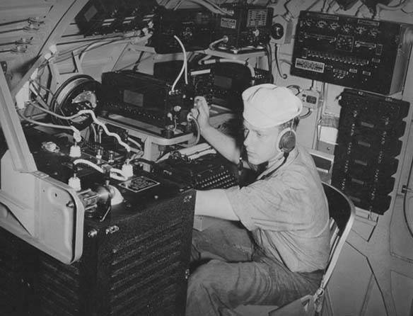
photo: USN PBY Radioman - June 1943 QST


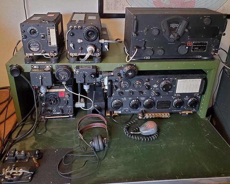
RU-16 Receiver and GF-11 Transmitter


photo above
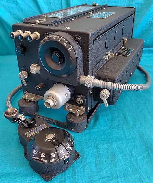
: RU-16 Receiver - serial number 8989
 

Brief History - The earliest RU Series of aircraft receivers date from about 1930 and the earliest GF Series of aircraft transmitters date from about 1932. The early models were built by Aircraft Radio Corporation with Western Electric Company becoming involved in some of the later versions. Both the receiver and the transmitter evolved throughout thirties and, although the design was certainly showing its age by the start of WWII, the last contracts are from 1941 (for the RU-19 and GF-12.) Like all pre-WWII equipment, contracts were for very small quantities so the early versions are very rare. The most commonly seen RU/GF versions are the RU-16 and the GF-11 which were produced in fairly large quantities in the very early part of WWII (but apparently not used extensively in actual service compared to the contract quantities produced.) The contracts actually date from before WWII began for the USA, April 21, 1941, with Western Electric Company as the contractor. The RU-16 and the GF-11 both operated on +12vdc implying that the installation would be in earlier types of aircraft. By 1941, +12vdc aircraft power was quickly being replaced with the more efficient +24vdc power.
 

The intended use for the RU/GF equipment was in single-seater or two-seater airplanes (radio op/observer seated behind the pilot) but the manual also mentions "flying boats" as another possible user in the installation instructions. Each installation into an particular airplane was "custom fitted" with each of the connecting cables custom-built from supplied "bulk cable." Additionally, flex control cables were also custom-fitted and were built from supplied "bulk" flex control cable material. In some single-seater airplanes, the only place to install the radio gear was behind the pilot's seat, as in the photo below-right, so remote controls using flex control cables and spline drive flex cables along with remote switch boxes and tuning heads were installed to allow the pilot to have the essential radio controls in front of him.

The photo to the right shows the RU-GF installation in Grumman F4F-4 Wildcat, a large single-seater Navy fighter plane used on aircraft carriers during WWII. Note the ZB-3 Homing Adapter mounted on top of the RU receiver. Note that a flex control cable is connected to the dual range coil in the RU receiver. The coil set is most likely Range Q-G since this would allow the use of HF in the 3mc to 4.5mc range for comms and MW for 700kc reception of the ZB-3 Homing Adapter (the ZB-3 was a VHF to MW converter used to receive location signals sent from aircraft carriers.) Set up on the right is the dynamotor and to the left, mounted on the inside fuselage wall, is the Junction Box and the Antenna Relay Unit. Note that all of the cables are un-jacketed. The GF transmitter is at the very front of the photo and mostly out of view with just the top showing.


photo above
: The interior of a Grumman F4F-4 Wildcat single-seater airplane showing the area behind the pilot's seat where the radio gear was mounted.
  photo from: www.ww2aircraft.net


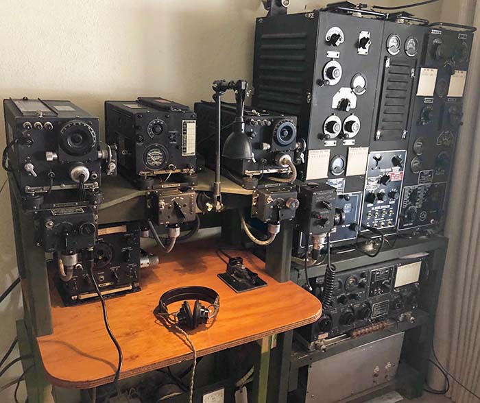
photo above: USN Radioman onboard a PBY tuning the RU-18 receiver (using the MC-127 direct coupler) and adjusting a GO-9 transmitter (pre-flight adjustments.) There's a second RU receiver on the right side of the desk riser (just behind the op's head.) Behind the op's chair on the wall are extra RU coil sets. Between the receivers is a LM frequency meter. Note the "mill" in front of the op.

Other Uses and Versions - There is also evidence that some RU-16/GF-11 gear was installed into a few small Navy boats and that some vehicular installations may have occurred from time to time. The USMC is said to have had some vehicles equipped with RU/GF gear. Not all RU-Series receivers were paired with the GF-Series transmitters. The RU-18 was usually paired with the much larger GO-Series transmitters (see photo left and header photo.) Some RU-Series receivers were setup in "receive only" stations while others might just be used for DF purposes. The RU-17/GF-12 were the 24 volt versions. For quick identification the data plates on the 12 volt units had a black field while the data plates on the 24 volt units used a blue field.

There was also a U.S. Army version of the RU/GF equipment, the SCR-AL-183. The receiver was designated as BC-AL-229 and the transmitter was BC-AL-230. The contracts are from the late-thirties up into 1940 with Western Electric as the contractor. This equipment is very similar in appearance to the RU/GF equipment but internally both the receiver and transmitter abound with minor differences. The SCR-AL-183 was the 12 volt version and the SCR-AL-283 was the 24 volt version. The Army versions were also intended for one and two-seater aircraft installations and are found in both black wrinkle finish and in bare aluminum.

Peripheral Equipment Required - The RU/GF equipment required a considerable quantity of peripheral devices that were absolutely necessary for operation of the receiver and transmitter. This use of many separate units allowed the user to "customize" the installation for the particular aircraft. Maintenance also was somewhat easier since repairs might only involve changing out a small box rather than the entire receiver or transmitter. This concept of multiple components necessary for aircraft radio operation had started in the late-twenties and seemed to continue on through the thirties. During WWII, the multiple separate component approach was still found in the Command Sets with Aircraft Radio Corporation and Western Electric as primary contractors. Other WWII communication designs had moved on with designs from RCA with the ARB, BC-224 and BC-348 or from Collins Radio Company and their ATC and ART-13 that were mostly single units with a minimum of external devices required for operation. 

Ultimately, the ease of installation and superior performance from the later WWII gear was probably responsible for all of the NOS or NIB units that can be found for the RU/GF equipment, especially the RU-16 and GF-11. The overall use of the RU/GF gear was very low by late-WWII. This non-use resulted in many complete RU-16/GF-11 equipment packages being sold on the post-WWII surplus market "new in the box" which accounts for the "fairly common" status of the RU-16/GF-11 nowadays. However, the "multi-component" design approach has made it a challenge to find all of the peripheral devices necessary to build a complete and operational RU/GF station.

RU-16 Receiver Circuit


The earliest RU receivers used triode tubes in a TRF circuit with tracking BFO. A tracking BFO utilized an identical section of the main ganged tuning capacitor along with coils that allowed adjustment of an oscillator to "track" or "tune along with" the tuned RF frequency accurately. Usually, a tracking BFO would be set one kilocycle higher than the RF tuned frequency to allow a heterodyne to be audible, allowing demodulation of a CW signal. All early RU receivers were built by Aircraft Radio Corporation. The early RU versions didn't have an AGC circuit. Additionally, tuning range was limited by the few available coil sets. By early 1941, the RU-16 had been designed. It was the first version of the RU to use an AGC circuit. Six tubes are used in the RU-16 circuit which is still a TRF (tuned radio frequency) receiver with tracking BFO. The tubes used are 1RF - 78, 2RF - 78, 3RF - 78, AGC - 77, Detector - 77, AF Out/BFO - 38233 (aka 1642.) The last tube, type 38233/1642, is a dual triode that provides the tracking BFO with one triode and the Audio Output stage with the other triode. The plug-in coil assemblies each contain five shielded coil units - three units that determine the RF tuning range of the assembly, one coil is the detector coupler and one unit for the tracking BFO coil required. The "dual frequency range" coil assemblies contained an internal switch that was operated by lever located on the front of the assembly. The single range coils had a metal handle-type strap for removing the coil from the receiver. 

Antennas - There are two antenna inputs, A and L - L. The L - L terminals are for a "homing loop" antenna. The Antenna or Loop switch could be set up to operate locally at the receiver or remotely via a flexible cable. The A terminal could be connected to any of the typical aircraft antennae available and depended mainly on what type of airplane was involved. Most single-seater airplanes had a wire antenna from the cockpit to the tail. Two-seaters usually had an aerodynamic mast near the airplane nose with a wire running to the tail. A central wire dropped down beside the rear-seat part of the cockpit and entered the side of the fuselage for the radio gear connection (a "T" antenna.) Some installations used a trailing wire (depended on the aircraft.) It was also possible to use the DU, DU-1 or DW-1 Amplified Direction Finding Loop which worked with an external sense antenna to provide a "true direction" cardioid pattern that allowed determining a correct bearing towards an unknown location signal. The output of the DU/DW Loop was connected to A on the RU receiver. The complete RU/GF setup provided power to operate a DU-type loop.

The AGC Circuit -  Homing Loops provided a "figure-8" pattern with two deep nulls off of each side of the loop. The loop would be set athwartship and then the airplane steered toward the null. The general direction was known and the "homing loop" provided accurate navigation to a specific airport or Radio Range Beacon along a defined airway. A "Test Meter" could be used as a signal carrier level indicating device. Since "Homing" assumed a modulated carrier beacon was to be tuned (the constant tone of the A and N combined modulation plus the carrier when on the beam,) the receiver must be in AUTO for the meter to indicate RF amplifier cathode current that varied because the AGC tube was controlling the RF Amplifier's grid bias when in AUTO. The AGC tube rectifies the modulated wave envelope from the third RF amplifier (before the detector tube) and develops the AGC control voltage based on amplitude of the carrier wave. The modulation level doesn't significantly affect the AGC bias voltage due to filtering within the RU circuit. The meter is inserted in the RF cathode circuit to ground. Since the pilot would be flying in the direction indicated by the loop's null, he would be looking for the weakest signal which is indicated by the highest reading of RF amp cathode current. If the airplane drifted off course, the loop would not be pointing at the null and the signal carrier amplitude would increase which would cause an increase in the AGC bias, increasing the RF amp grid bias and reducing the RF gain and reducing the RF amplifier cathode current resulting in a lower meter reading. Once the pilot was on course he watched the meter and if it began to show reduced current, he knew the airplane had drifted "off the beam" and required some course correction. Since the AGC tube control is before the detector and has significant TC loading, AUTO (AGC) can also be used with CW operation. Since the RF amplifier tubes' cathodes are grounded in AUTO, the output level (INCREASE OUTPUT dual potentiometer) is controlled with a variable resistance on the audio output line. In MANUAL, a variable resistance (dual pot INCREASE OUTPUT) is connected into the RF amplifier tubes' cathode circuit to control the RF Gain of the receiver and the audio output level is fixed at maximum output. The switching of the dual pot's functions is accomplished by the Receiver cabled connection to the Junction Box and the Receiver Switch Box cabled connection to the Junction Box.

GF-11 Transmitter Circuit


photo above
: GF-11 Transmitter - serial number 8888
 

The GF-Series started in 1932 and had a number of changes that run up to the GF-12 version. The GF-11 transmitter differs substantially from the early-1930s versions of the circuit that employed two type-10 tubes as modulators, a type-10 PA and a type-45 as an oscillator. The early GF transmitters only had one coil set so frequency options were limited. As the GF evolved, more coil sets were provided and the power output was increased from 3 watts up to about 15 watts. The GF-11 dates from 1941 and uses two type 89 tubes and two type 837 tubes. One of the 89 tubes was the master oscillator tube while the second 89 could be a MCW audio oscillator, an audio sidetone generator on CW/MCW or a Voice modulator depending the the mode selected. The two 837 tubes were operated in Push-Pull as the power amplifier. The 837 screens and suppressor grids were tied together and modulated by the type 89 AF tube in the MCW and Voice modes. The two 89 tube filaments are connected in series for 12vdc operation and the two 837 tubes are connected in parallel (837 tube uses 12 volt filaments.) Low voltage (+12 to +14vdc) was supplied by the aircraft battery/charging system buss and B+ was supplied by the shared dynamotor, that is, both the RU and the GF obtained their B+ from the same dynamotor (CW-21109A) and various resistor dividers within the circuits of each unit. Tuning ranges are determined by plug-in coil sets that provide a frequency range of 2000kc to 3200kc and from 3000kc to 9050kc. Eight plug-in coil sets were supplied with the GF-11.
 
RF power output for the GF-11 was about 2 to 7 watts for all modes in the 2-3mc range and 12 to 15 watts in all modes in the 3-9mc range. The meter is a Thermocouple-type RF amp meter (the radio op tuned for maximum RF current to the antenna.) There were two PL-68 phone jacks on the side of the GF-11 that provided meter access to measure Modulator current and also the PA plate current. The RU-series Test Meter (optional for the RU-16) could be used to measure these points if desired (MOD I was direct but PLATE I had an internal shunt to scale the meter to 5x I.)

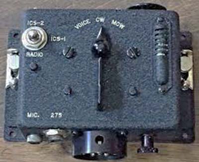
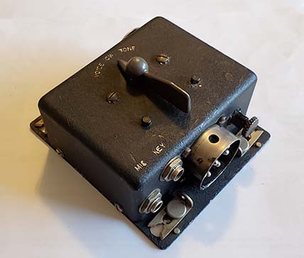
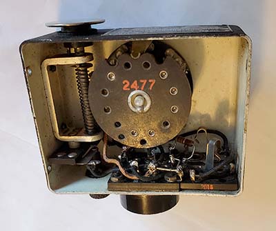
Absolutely necessary for operation was the Transmitter Control Box CW-23097 (shown in the photo to the right.) This box had the switch for CW, MCW or VOICE modes of operation, RADIO-ICS switch, a neon +HV indicator, input jacks for an external key or mike. The eight-pin box receptacle is for the cable that connects to the Junction Box. The GF-11 and the Transmitter Control Box are interconnected through the Junction Box. On top of the Transmitter Control Box was a hand key button for CW/MCW.
 

More "absolutely necessary" devices in the next section,...


photo right: CW-23097 Transmitter Control Box

The Ancillary Pieces
(The Peripheral Devices Absolutely Necessary for Operation)

The RU-16/GF-11 (actually the entire RU/GF series) required a considerable collection of peripheral ancillary equipment that had to be interconnected using special cables to actually operate the receiver and the transmitter together along with the dynamotor operating from the aircraft battery-charger buss. This design approach was utilized to ease the task of custom installations within several different types of aircraft. Each type of airplane required setting up the equipment to have necessary control boxes within reach of the pilot but with the equipment mounted elsewhere. Several interconnection cables allowed easy removal of defective devices when maintenance or replacement was necessary. 

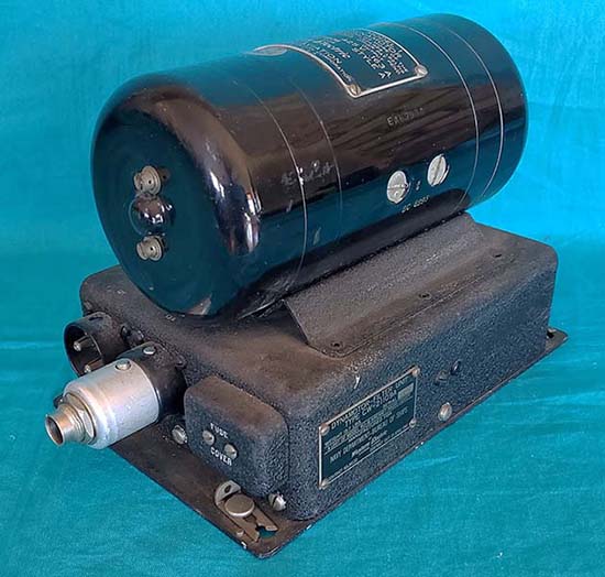
The Dynamotor-Filter Box - CW-21109A -  The power source for both the RU-16 and the GF-11 is the dynamotor. The dynamotor is mounted on top of the Filter Box which contains the various circuitry components. The voltage input is +12vdc up to +14vdc with better efficiency of operation at the higher input voltage. Running current is between 8 amps and 10 amps depending on the load but initial surge current is quite high (probably >35 amps.) A two conductor cable connected the dynamotor to the aircraft battery-charger buss. To be able to "turn on" the dynamotor from a remote switch box (the CW-23096A) required a relay inside the Filter Box that was operated by battery-charger voltage and the remote switch. The relay had very large contacts for conducting the fairly high current to the "motor" side of the dynamotor. The operating output voltage depended on the battery input voltage and also on the output load but generally was between +350vdc and +400vdc when operating both the RU-16 and the GF-11. Negative bias voltages were required for the GF-11 and for the RU-16 AGC tube. By elevating the output negative wire from the "generator" above chassis using a 1000 ohm WW resistor and a 140 ohm WW resistor in series to chassis, a voltage divider network allowed about -95vdc and -80vdc to be available for bias requirements. The dynamotor itself was built by Eclipse Aviation for Western Electric.
 

Cables and Plugs - In addition to several peripheral boxes there was an array of specifically "identified by number" interconnection cables with special connector plugs with unique pin patterns or different diameters that interconnected the RU-16/GF-11, the Dynamotor and the various switch boxes through the Junction Box. Originally, bulk cable was supplied with the equipment and each interconnection cable had to be custom-built using the correct type bulk cable with the correct connector plugs installed. Additionally, the bulk cables were "un-jacketed" to allow the cable shields to be easily bonded to the aircraft frame for lowest noise pickup. Cables were supposed to have a metal identification tag installed during construction. Since each installation was "custom-fitted" to the aircraft many times the original RU-GF cables remained in the aircraft. NOS equipment that was never installed won't have cables that are complete but might have the plugs necessary to build a set of cables. But, what is found today are mostly separated RU-GF connector plugs (both used and unused) that have to be used to build new cables. Most plugs unless they are genuinely for the RU-GF equipment won't have an identification that correlates to the manual information. Original plus were identified with a single number stamped on the shell. Some of the plugs required were used in other equipment so these plugs lack the specific identification but still function correctly. The connector-plug pin numbering is unique to each type of plug, that, and the pin patterns have to be used to identify an unmarked plug. A typical plug is shown installed in the dynamotor photo to the right (it's a #134 plug.) 


photo above
: RU-16/GF-11 Dynamotor CW-21109A - serial number 6142.


photo above
: CW-62008A Junction Box with many of the required connector plugs partially inserted. Note that some of the plugs do have identification numbers on the shell. Plugs 37 and 80 are substitute plugs that are required for "receiver only" operation (both plugs) or for "single-seater" aircraft installation (80 only.) Box receptacles 74 and 76 are provided to power accessories like the LM-type Frequency Meter, the DU-1-type amplified loop antenna or the ZB-type Homing Adapter.
 

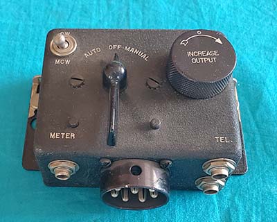
Junction Box, Switch Boxes and Substitute Plugs -  The Junction Box is essential for the proper interconnecting and operation of the entire RU-GF system. Likewise, the Dynamotor is necessary to provide B+ voltage to both transmitter and receiver by way of its connection to the Junction Box. To actually operate the RU-16 receiver required a large 11 wire cable from the RU-16 to the Junction Box. The RU-16 Remote Switch Box (photo below) was also connected by a cable to the Junction Box to provide the RU-16 with switching for CW/MCW, for selecting AUTO/MANUAL along with ON/OFF function for the entire system, a Gain control for the receiver output, two phone jacks for the audio output, a three-circuit phone jack for the Test Meter. 

To operate the GF-11 transmitter required its nine wire cable to connect to the Junction Box and the Transmitter Control Box was also cable-connected to the Junction Box. There was also a GF-11 Extension Control Box that connected to the Junction Box (its use was optional and intended for two-seater airplanes) and a Remote Transmitter Control switch (this was user supplied and connected to the phone jack on Junction Box and operated the PTT/T-R line.) For single antenna T-R operation the Antenna Relay box was necessary (it also connected to the Junction Box using a small two pin plug and cable.)

There was also an optional and externally connected "RU Test Meter" that could be added to the setup (PL-68 plug inserted into the RU-16 switch box for Homing or into jacks on the side of the GF-11.) There were two connectors (74 and 76) on the Junction Box that could be used to provide voltage to operate a LM-type CFI (Crystal Frequency Indicator, aka: heterodyne frequency meter) or an amplified loop antenna like the DU-series. It was also possible to power a "Homing Adapter" like the ZB Series from either connector 74 or 76.

Two "substitute plugs" were supplied and must be installed in the Transmitter Control Box connector and the Extension Control Box connector (37 and 80) of the Junction Box if a "receive only" setup was intended. If the Extension Control Box wasn't needed such as in a single-seater airplane then only sub-plug 80 is required. These "substitute plugs" each had an internal jumper to route the circuitry as necessary for this type of operation. Sub-plug 37 grounds the 38233 tube cathode so the receiver will function without the Transmitter Control Box's "RADIO/ICS-1/ICS-2" switch and sub-plug 80 completes the circuit so the Remote Transmitter Switch will function without the Extension Control Box.

Flex Cables, Extension Key, Microphone & ICS - Remote Loop-Antenna Switch flex cables and Remote Tuning Range Switch flex cables were included in the package but their use depended on the ultimate installation requirements. These flex cable connected controls were necessary in some single-seater installations where the radio gear was located behind the pilot and only the remote controls and switch boxes for the radio operation were up front. The flex cable was also supplied in bulk and each remote flex cable had to be custom-built for the installation requirements. An external telegraph key (called an "extension key") could be used, a carbon mike like the RS-38 was needed if Voice operation was desired and a set of Lo-Z 'phones (600Z ohms) was also necessary. The ICS (Inter-Communication System) provided a method for the radio op to talk to the pilot through the use of the Transmitter Control Box by switching to ICS-1 or ICS-2 and working into the pilot's Extension Control Box (GF-11 audio tube used for two-way mikes and RU-16 output transformer would drive the phones.) ICS-1 allowed intercommunication with the radio signals still audible and ICS-2 removed the radio signals and only allowed the intercommunication (this position was "spring loaded" so the receiver signals couldn't be "locked out.") Selecting ICS-1 or 2 also disabled the PTT at the transmitter so only the AF tube operated while using the intercommunication function. The ICS connection to the RU-16 audio output grid provided the sidetone through the 'phones when in "RADIO" on the Transmitter Control Box and when in the CW or MCW modes.

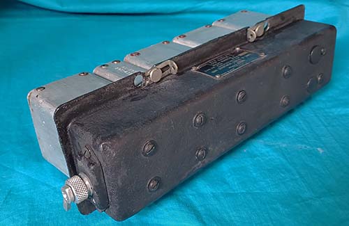
Plug-in Coils - In-Flight Use - All plug-in coils for both the RU-16 and the GF-11 are somewhat difficult to extract out of either piece of equipment. When the radio equipment installation was behind the pilot's seat then the coil set necessary for the RU and the coil set for the GF had to be installed during pre-flight setup. The dual range RU coils allowed the pilot two receiver tuning ranges that could be easily selected during flight using a flexible control cable installation. A dual range coil would allow the pilot a HF range for comms and a MW range for nav-beacons or reception of a ZB-type homing adapter. Single range coils were used when only one operating frequency range was going to be needed. The GF coils were only single range and the required coil set to be installed in the transmitter during the pre-flight setup for the intended operating frequency. On larger airplanes with a radio op the RU-GF installation was usually more accessible and the possibility of changing coils did exist. These installations had to have the RU receiver accessible on its right side for coil changing operations. Likewise the GF transmitter had to be accessible on its left side for coil changing operations. Although the receiver coil changing might have happened, retuning the GF transmitter for a frequency change might have been too involved to be carried out during a flight. If a transmitting frequency change was thought necessary, it would be difficult to accomplish since the coil set would have to be removed and the coil tap moved to a different position. The approximate position would perhaps be noted on the GF-11 front panel tuning chart, which would help. Then the coil set reinserted and the Antenna Condenser tuned for maximum antenna current. This procedure would never have been possible in a single-seater airplane and would only have been possible in larger airplanes with a radio operator onboard.      More Coil Set Details - The RU-16 was supplied with four "dual frequency range" coil sets and five single range coil sets. The coils supplied allowed the radio op coverage from 190kc up to 13.575mc using various coils that were combinations of either dual range or single range coils. The normal five single range coils allowed coverage from about 500kc up to 13.575mc. For MW and LF coverage, the dual coil sets O-P, Q-G and L-N were necessary and allowed coverage from 190kc up to 800kc. There were several other coil assemblies listed in the manual but only four dual range and five single range coil sets were normally supplied with the receiver. Each coil assembly originally had a specific metal case to store it in, minus one. That is, for the nine coils, eight containers were supplied since one coil set would be installed in the receiver. The additional coil sets that were a not supplied were different combinations of frequency ranges on dual range sets and slightly different frequency ranges on the single range coils. Ultimately, even if every coil set were available, the same 190kc to 13.575mc would be the extent of the frequency coverage of the receiver.

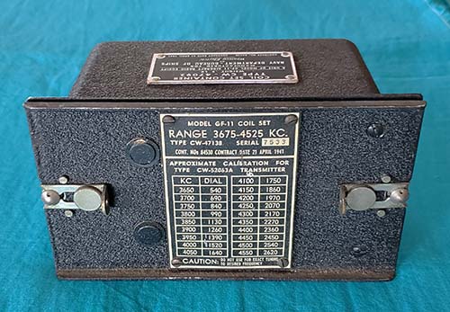
The GF-11 also had its own plug-in tuning modules and each of those also originally had a metal container for protection during storage. Eight GF-11 tuning modules were supplied allowing the transmitter to operate from 2.0mc up to 9.05mc.


photo above: A RU-16 Single Range plug-in coil assembly for tuning Range E. Note the "extraction" handle. Also, five shielded coil units that function as (3) RF coils, (1) Detector-Coupler coil and (1) Tracking BFO coil. Tunes from approximately 1200kc up to 2100kc.


photo right: A RU-16 Dual Range plug-in coil assembly. This is the O-P Range coil set with a total coverage using both ranges of 187kc up to 455kc. The switch lever is located on the front-facing part of the coil assembly and is marked "FREQ - HIGH - LOW."


photo above: GF-11 coil set for 3675-4525kc in storage container

Interchangeability - Many of the ancillary pieces are interchangeable to the RU-16/GF-11 from the RU-17/GF-12 and RU-18 receivers and possibly earlier versions. It depends on what the piece's function was. The Receiver Tuning Head, for example, since it's entirely mechanical and the tuning dial scale is 0 to 100, is interchangeable within many of the RU-series receivers. Uniquely necessary for 24 volt operation is the proper Dynamotor, Junction Box and Antenna Relay Unit. The 24 volt receivers just have a voltage divider in the circuit to basically operate a 12 volt receiver on 24 volts. The NAVAER 08-5Q-100 manual is very specific with two pages of possible interchangeability of the various pieces for both the RU and GF equipment.

Additionally, since the RU receivers are fairly broadbanded and the coil sets were very consistently manufactured, the RU coil sets will normally function from receiver to receiver. Minor "tweaking" might be required for absolute best performance but for general testing of coil sets, any RU receiver will usually provide an adequate "test bed."

photo above: Receiver Switch Box CW-23096A. The INCREASE OUTPUT control actually is a dual pot that controls the RF gain in MANUAL and Audio output level in AUTO.

More RU/GF Ancillary Pieces

1. Receiver Tuning Head - CW-23012 - Depending on the installation, the RU-16 might have required a Receiver Tuning Head that was connected to the tuning gear box by way of a flexible spline cable similar to old car speedometer cables. The spline flex cable was also supplied in bulk lengths and custom fitted for the installation requirements. Shown in photo 1 is the Type CW-23012, in this case, for the RU-17 (blue tag) but most ancillary components were interchangeable between the RU-16 and RU-17. Since the tuning dial on the receiver and on the remote tuning head were both scaled "0 to 100," a tuned frequency versus dial readout chart was attached to the top of the receiver's tube cover plate. The fiducial could be mounted in several positions around the dial perimeter to allow mounting the Tuning Head in the best position for pilot or radio op visibility in the particular installation.

2. Direct Coupler - MC-127 - For "local" operation of the receiver tuning there was a small direct coupler tuning adapter that could be installed in lieu of the Receiver Tuning Head. Where the installation allowed the radio op to have the receiver in front of him, the MC-127 coupler eliminated the flex drive cable and remote tuning head. Often times, the MC-127 greatly reduced the backlash that was inherent in the flex drive cable operation. However, the miniscule size of the MC-127 hampers easy fast tuning with the crank and most tuning is done slowly by using the "fingers on the wheel-rim perimeter" approach.

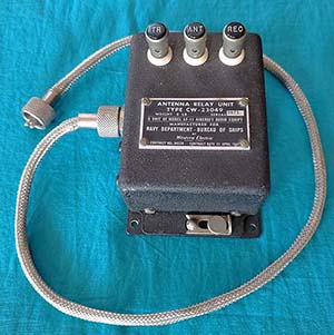
3. Antenna Relay Unit - CW-23049 - If a single antenna is used for both receive and transmit then the Antenna Relay Unit must be used. It is driven by the GF-11 PTT through the Junction Box and the Antenna Relay Unit is connected by a two conductor cable to the Junction Box. Push-terminals for Antenna - ANT, Receiver - REC and Transmitter - TR. Ground is achieved through the case being mounted to the airframe.

4. RU/GF Test Meter - CBY-22266 - The Test Meter was optional for the RU-16/GF-11 gear. The Test Meter is mentioned in the manual as desirable for a visual indicator for Homing. For RU interfacing, a PL-68 plug is inserted into the Meter Jack on the Receiver Switch Box. The Test Meter is also mentioned in the manual for use with the GF-11 transmitter. The PL-68 plug can be inserted into the MOD jack or into the PLATE jack that are on the left side of the transmitter. In PLATE, a built-in shunt reduces the current so there is a factor of five times the meter scale reading for actual PLATE current. The GF-Meter shown was built by Aircraft Radio Corp. for the GF-8 but it can be used with the GF-11 since all of the meter specifications and requirements didn't change. The CBY-22266 is a very usable and informative accessory for both the RU-16 and the GF-11,...well worth having,...although using a PL-68 plug and cable running to a typical DC current meter would also function fine. Be sure to make your cable long enough,...the one shown in the photo is way too short.

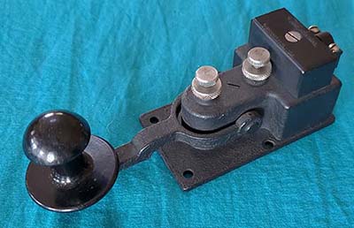
5. & 6. Telephonics Corp. - RS-38 CTE-51004-C and CTE-26003A - The RS-38 is a handheld carbon microphone with push-to-talk button located on the top of the mike and features a "noise cancelling" mouth piece. The RS-38 is specified as the mike to use in the manual although a "noise cancelling" T-17 would also work. The mike uses a PL-68 plug. The Transmitter Control Box had a jack for an extension telegraph key using a PL-55 plug. There was a large button-type key on top of the Transmitter Control Box but it's awkward to use and limited in its ability to send decent Morse. For Morse proficient radio ops, the 26003A was a well-built "flame proof" key to use with the GF-11 and in the hands of a good radio op could allow excellent Morse to be transmitted. The "mushroom head" knob is standard for the 23006 key. Both the RS-38 and the 23006A shown are from Telephonics Corp.

1


2


3

4


5

6


RU-16/GF-11 -  Operational Transmit-Receive Station
A Component Hunting, Rebuilding and Sometimes Restoration Project

Certainly finding and acquiring or building the large quantity of necessary peripheral equipment for the RU-16/GF-11 is a daunting task. However, as more and more pieces were found, it then became much easier to envision a complete and operational station. The challenge for the finished station is very low output power using the GF-11 running about 15 to 20 watts output on CW or about 10 watts carrier power on Voice (15 watts PEP.) On Voice, the supressor-grid modulation combined with the RS-38 carbon mike will make almost any QSO difficult except for those local hams that are on the Vintage Military Radio Net. CW can be used for those mil-rad hams that are further away. However, KD6TKX (near Coalinga, CA) has worked a two-way AM Voice QSO with NI6Q (Flagstaff, AZ) using his RU-GF station (11 watts AM carrier output power.) So, QRP with an efficient antenna system has possibilities.

June 2021 - This project started a few months back with the acquisition of an excellent condition, very original and possibly unused RU-16 that was only missing a few minor exterior small parts (the shock mount and the mounting brackets.) I already had the CW-23012 Receiver Tuning Head but I had to find a spline flex cable drive for it to interface with the RU-16. I then started looking for and gathering up more of the needed accessories. I found that I had a lot of the connectors in my junk boxes. A very nice condition GF-11 transmitter was donated by WA6OPE (with the connector plugs.) W7MS donated a "parts set" Army BC-229 to provide the missing but very necessary slide-clip brackets for the shock mount for the RU-16. KD6TKX donated a large box of parts that included both shock mounts, the Junction Box and the Antenna Relay plus many loose connector plugs. Acquired on eBay was the Dynamotor, found only because it was listed just by the CW-21109A part number. Also, a couple of RU-16 coil sets (one NOS in the original box,) a RU-16 switch box, a second Junction Box (for needed connector plugs, mounting base and other parts) and a very necessary repro manual. Around here in the various parts boxes I found a very nice condition, early-style RS-38 mike (Telephonics mfg) and a really nice CTE-26003A Navy key (also Telephonics mfg.) I have several 600Z Navy headsets that can be used. Also, I have a LM Heterodyne Frequency Meter that still had the original power input connector and the original cable with correct plugs for the RU/GF Junction Box connection (and internally it was already set up for 12vdc and +200vdc to +400vdc B+.) I'm still looking for the GF-11 Transmitter Control Box CW-23097. Of course, there are a multitude of other minor extras that, if found, would be nice to have. But since I do have enough of the parts necessary to go through the receiver and get it operational, that part of the project can get underway.


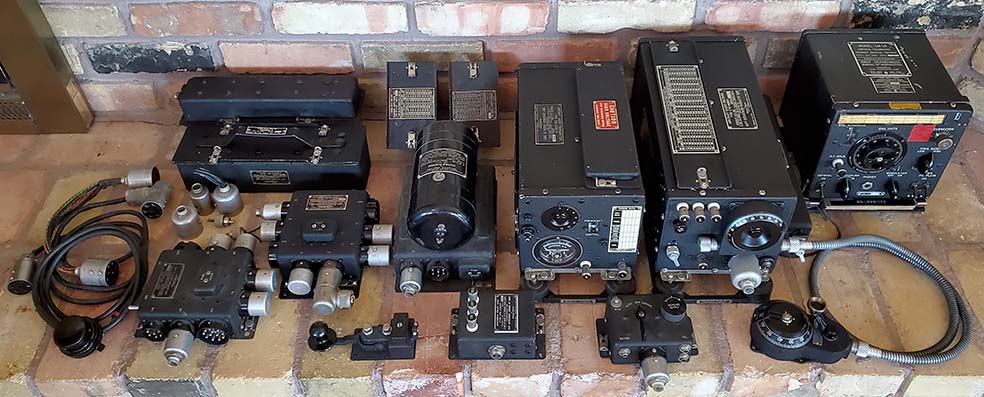
photo above: Some (but not all) of the RU-16/GF-11 station components. Still needed is the GF-11 Transmitter Control Box CW-23097. To be authentic, all cables have to be custom-built for proper length and also to be fully shielded. The shielded cables didn't have a rubber jacket originally and that's how these station cables will be built. A minimum of six cables are required and two more for powering various accessories like the LM Heterodyne Frequency Meter (far right) or the DW-1 loop antenna (not in photo.)

RU-16/GF-11 Project Details

Dynamotor Check-out

The first step is to make sure that there is a functional power source - the dynamotor. SN:6142 looked like it was NOS and had never been used and probably only ran for the initial testing. Even the grease in the bearings wasn't too dried up,...well, it was crumbling a bit, so it probably was 80 year old grease. The commutators were very flat and had only a slight darkening where the brushes were riding (probably while testing.) The manual and instructions inside the end bells indicated that the bearings should be greased about every 300 hours of operation. The manual further says that the dynamotor shouldn't be completely disassembled unless there was a specific problem. Since everything looked in "new" condition, all I did was clean out the old grease with WD-40 and an acid brush. I then repacked the bearings with modern wheel bearing grease.

Dynamotor Input Power - What Didn't Work - I had an old Astron 35 amp power supply out in the shop storage. I had always heard that the Astrons wouldn't run dynamotors because of the initial surge current is high enough to "current limit" the power supply because the dynamotor appears as a "short circuit" if the armature isn't rotating. I thought the Astron 35A might work because I had been using it to run a dynamotor-operated BC-224 which it did quite well. However, when connected to the RU-GF dynamotor the internal start relay just "chattered." I had 10 gauge wires for the battery input connection so I didn't think there was much of an IR drop. It was probably the Astron 35A protection circuitry current-limiting the output. Dynamotor Input Power - What Does Work - The next test was with the PP-1104-C. Normally, I have this supply set up for +28vdc at 50A for various DC operated transmitters in the shop. By moving two links that are on the front panel, I can easily set up the PP-1104-C for +14vdc at 100A. The PP-1104-C runs the RU-GF dynamotor perfectly. Instant start with no hesitation (and what else should be expected when there's 100 amps of current available?) While running, the current draw shows <10 amps with no load (the PP-1104-C current meter is a field replacement meter that is similar to the original but doesn't seem very accurate.) The instantaneous surge current almost "pegs" the 100 amp full scale meter (although some of that might be meter needle inertia.) At any rate, unless I want to operate the RU-GF station out in the shop, I'll have to find a more convenient-to-use, high-current 12vdc power supply.

Also out in the shop is a fairly large and really heavy Lambda LK-351-FMOV-5104-4 linear supply that's rated at 40 amps but the current meter FS is 20 amps. Voltage is adjustable 0-40vdc. I set the output voltage to +14vdc and the current limiting to 20+ amps (no limiting.) The Lambda LK-351 also powered the RU-GF dynamotor without hesitation. The instantaneous current surge measured about 18 amps on the 20A FS meter but that meter is pretty heavily damped so the 40A maximum current that the LK-351 is rated at was probably needed for the instantaneous surge current. At any rate, the LK-351, although it weighs around 100 pounds, is physically much, much smaller than the PP-1104-C, so it's a practical power supply to run the RU-GF station.    And thanks to John, N9AMI, the Lambda is now in the upstairs lab-workshop setting on a small furniture dolly so it can easily be moved around.

Testing the RU-GF Dynamotor - Although getting the motor part of the "motor-generator" operational is certainly important, so is having a functional "generator." At first glance, it looked like everything was okay. With +14vdc input I was getting about +500vdc output "no load." I attached a 5000 ohm 100W resistor as a load to draw 100mA and everything still looked fine with the expected drop in output voltage and increase in supply current. I then disconnected the load since the resistor was getting warm. When I went to check the negative voltage, which is created by elevating the negative side of the dynamotor output above chassis with a 1400 ohm resistor - actually a 140 ohm plus a 1000 ohm in series. The resistor divider network provides about -100vdc bias voltage for the transmitter requirements and a lower bias voltage of about -80vdc for the AGC tube in the receiver. Unexpectedly, I didn't measure any negative voltage referenced to chassis (which certainly caused "instant" worry.) But, one has to look at the circuit to see that with "no load" there won't be any output current flowing and so the voltage divider won't function. I reconnected the 5000 ohm load to the output and then measured -95vdc and -80vdc at the divider network. Normally, a quick "no load" test of the dynamotor is sufficient but since both the transmitter and the receiver utilize the negative bias voltages developed in the dynamotor filter box, a full test required that a resistive load be connected to the output to have sufficient current flow to test the voltage divider function.
Building the Cables

Cable 3158 connects the RU-16 Switch Box to the Junction Box. I have both plugs to build a complete cable. *
Cable 3150
connects the Antenna Relay Box to the Junction Box. I have both plugs to build a complete cable. *
Cable 3162
connects the GF-11 to the Junction Box (have both plugs for a complete cable.) *
Cable 3154
connects the Dynamotor to the +14vdc and only requires one plug which I have. *
Cable 3160
connects the RU-16 to the Junction Box. I only have one #233 plug so this cable will have receptacle sockets on one end - Completed 3160 w/ both plugs August 10, 2021*
Cable 3156
connects the Dynamotor output to the Junction Box. I only have one PL-65 plug so this cable will have receptacle sockets on one end. *
Cable 3148 I have two each of the #37 substitute plugs. When a Transmitter Control Box is found, then the two #37 plugs can be used to make the cable. *
Cable 3152 I have two each of the #80 substitute plugs. If an Extension Control Box is found then the two #80 plugs can be used to make the cable.

* = cable completed - the last of the required cables (3162 and 3148) were completed on Sept. 18, 2021.

Rather than harvest RG-8 shield, which would be untinned-copper, to build these cables, I bought tubular braided shield made out of tinned-copper. This will result in more authentic looking cables. Also, rather than harvest wire from the junk boxes, I bought 250 feet of 16 gauge stranded multi-color insulated wires for the cable building part of the project. Most of the cables will be between 24" to 30" long. The exception will be Cable 3156 (dynamotor output) which will be 36" long to allow the dynamotor to be under the table and closer to the floor. Since all cables are routed to the Junction Box, I think the best location for it, that would result in the shortest cable connections, would be behind and between the RU-16 and GF-11, either above or below these units. The connection of the shield to the shell of each plug is unusual in that the original bulk cable plus shield was a "press fit" into the rear fitting of the plug shell. No soldering was needed. Some of the replica cables will have to be "padded" with a wrap of electrical tape under the shield at each end so the cable. The shield will compress the tape as the plug shell is slid into place. The result will be a tight fit to the shield that exits the plug shell fitting.

Wire Receptacle Sockets - This is a temporary solution to the problem of missing PL plugs. The inner diameter (ID) of these sockets should be about 0.154" but almost all small brass tubing is about 0.122" which is too small. McMaster-Carr has 1/4" copper tubing with thicker walls with an ID of 0.151" but the 1/4" OD is too large for fitting into the box receptacle connector with multiple pins. Although it sounds sort of "Rube Goldberg," old style alligator clips with a rear socket that was meant to fit on to banana pins are a perfect fit. The ID is a good tight fit at 0.154" and the OD is about 0.195" leaving sufficient space between the sockets when installed in the box receptacle. The bad part is that an alligator clip has to be sacrificed by cutting off the back of the alligator clip and reshaping the cut part slightly to allow soldering the wire there. Then a piece of shrink tubing is installed over the receptacle piece. I used the old type copper plated alligator clips. I had to make 11 of these for the #233 box receptacle on the Junction Box and six were needed for the #134 box receptacle on the Junction Box. When the proper plugs are found they can easily be installed in place of the receptacle sockets.

PL-type Shell Problems - When these types of plugs were new, the inner bakelite plug would just slide out of the shell. There was a ground screw that held the shell in place. Apparently, after 80+ years of existence, some of these shells have become permanently attached to the bakelite plug. In moderately "stuck" cases, the bakelite plug can be pushed out of the shell by using a 3/16" diameter rod that's inserted through the cable hole and tapped with a small hammer to push the plug out of the shell. For best results, use a machinist's vise and place the edges of the aluminum shell just supported by the open jaws with the bakelite plug facing down. Now, tap the rod much harder and the bakelite plug should come loose. As the plug starts to come out, adjust the jaws to just clear the bakelite so the aluminum shell has good support. In most cases, this last method will work. But, in severe cases, it appears as though corrosion or some other process has reduced the inner diameter of the shell and has also created porosities that seem to "grab onto" the bakelite making easy removal impossible. In two cases, to remove the bakelite plug, I had to slice a slit in the aluminum shell using a Dremel tool being careful to not slice into the bakelite. Be sure to orient the slit near the screw mounting hole so the slit doesn't show when the plug is installed into its matching box connector when the cable is completed. Once the slit has been cut, then spread open the slit to expand the ID of the shell. This then allows the bakelite plug to be removed. To reinstall the bakelite plug will require some sizing of the inner part of the shell and the outer surface of the bakelite plug (using a file) to get a fit that will allow easy removal of the bakelite plug from the shell in the future. This "stuck" problem seemed to affect several of the PL-type plugs with two requiring the "slit trick" to extract the bakelite plug. The other stuck plugs were removed by tapping the rod with the plug on a machinist's vise trick which, luckily, works most of the time.

One other important connection is the 4-40 screw and lock washer that seems to only secure the shell. However, this screw (when installed) also connects the shell to the ground pin on each type of PL-plug which then connects the shield of the cable on each end to system ground.

Cable 3160 - #233 versus #133 plug - Although the #133 plug appears to be an eleven pin plug and it does fit the RU-16 box connector exactly, it isn't the correct plug. The only difference is that pin 89 is missing. Pin 89 is used to route the cathode of the audio output tube (one-half of the 38233 triode tube) to the switch in the Transmitter Control Box that selects RADIO, ICS-1 or ICS-2. When RADIO or ICS-1 is selected at the Transmitter Control Box, pin 89 from the RU-16 is routed to pin 89 of the #233 box connector on the Junction Box and internally pin 89 is connected to pin 46 on the #37 box connector which is then cabled to the Transmitter Control Box ultimately connecting the 38233 cathode via the switch to chassis and allowing the tube to function. When ICS-2 is selected, then the cathode connection to chassis is opened and the receiver audio is disabled, allowing intercommunication between the pilot and the radio op with the receiver output muted. The plug I had, a #133, had an embossed bakelite post where pin 89 should be on the backside of the plug and a hole in the frontside so the #133 plug would fit into #233 box connector.

I needed to modify the #133 to work as a #233. I used a copper alligator clip rear socket to make a receptacle that would fit correctly. The receptacle also had to be the proper size of 0.154" ID to receive the box connector pin with a tight fit. I had to drill out the bakelite post so the receptacle would fit into the hole and allow the smaller rear part of the receptacle to protrude out the back of the bakelite plug. I counter-bored the hole so the receptacle couldn't "push out" through the back. The receptacle was a tight press fit and once a wire was soldered to it, it can't be pulled out the front and the counter-bore keeps it from pushing out the back. The "test fit" was perfect so this modified #133 plug is now functional as a #233 plug that was used to build a workable 3160 Cable (inline sockets on opposite end.) 

Re-Do on 3160 Length - In estimating the length of this cable, I didn't take into account the bends as the cable leaves the front of the receiver and the bend behind the receiver to allow the cable to continue to the Junction Box. I had made the cable 26" long but I had to build a new cable that was 36" long to take into account the actual route of cable. The 26" cable will be reused as Cable 3162 that runs from the back of the transmitter to the Junction Box. Since Cable 3162 exits the back of the GF-11, the 26" length will work fine.

Cable 3160 Completed -  August 3, 2021 - I found another #133 plug which, after doing the #133 to #233 modification, will allow me to complete the 3160 Cable with plugs on both ends.  Aug 9, 2021 - Completed the modification changing #133 to #233. Aug 10, 2021 - 3160 Cable complete with #233 plugs on each end.

The Junction Box De-Mod - The box that's in the best condition and has the highest serial number also had some "hamster mods" that needed to be removed and the circuitry put back to original. The mod consisted of a toggle switch replacing the phone jack for the Remote Transmitter Control switch. Additionally, about five wires were added, three wires were cut and a jumper installed on connector 236. The mods were the typical sloppy hamster work with gloppy soldering. Phone jack #174, although a 1/4" barrel standard jack, is a Western Electric part so it is very different looking than a standard 1/4" phone jack. I thought I might have had to harvest the #174 from the "poor condition" Junction Box but, luckily, I found a phone jack that was very similar to the #174 in the junk boxes. I used correct style vintage wire to replace two mod wires (heavy plastic coated wire) and installed the "new" vintage wires in the original hook-up. The three cut wires just needed to be stripped, tinned and reconnected properly. The look-alike jack fit into the limited space correctly and was connected using the existing original wire that had been wired to the mod-switch. The finished Junction Box looks great and is now back to stock (I also checked the T-R relay for correct operation.) Also, the "poorer" condition Junction Box was kept complete and original for future reference needs (I tested both Junction Boxes for proper operation.)


Getting the RU-16 Operating

Initial Power-up - To operate the RU-16 required the dynamotor, the Junction Box and the RU-16 Receiver Switch Box. Also, Cable 3158, Cable 3154, Cable 3160 and Cable 3156 were needed. In addition, substitute plugs #37 and #80 were needed since this was going to be a "receiver only" setup. I had to take the Receiver Switch Box bottom off to clean the contacts on the MANUAL-OFF-AUTO switch. I had the dual coil set to LOW which covered the bottom part of the AM-BC band. With an antenna connected and 600Z phones plugged in, the switch was placed in the MANUAL position. Nothing happened,...the dynamotor didn't even turn on. I checked a couple of cables and then used an ohm meter to determine if there was a switch closure happening in the Cable 3156 (dynamotor output.) No closure was measured. A little further checking and I noted that in both cables that had individual sockets on individual wire ends were plugged in exactly opposite, like a mirror image, of what was correct (the problem of not having a second plug to complete the cable.) I reconnected the wire/socket ends on both cables properly to the Junction Box. After that, switching to MANUAL resulted in the dynamotor starting up and the tube heaters illuminating. After about 30 seconds, KPLY 630kc started coming in strong. I switched to HIGH on the range switch and connected a 40 meter antenna. I set the RU-16 to about 42 on the dial and switched on the BFO. I had to switch from LOW to HIGH a few times to "clean the switch contacts" and that resulted in good sensitivity. Several SSB stations could be heard and, if very carefully tuned, they even demodulated correctly. There was a very strong CW station heard that sounded very stable with a good note. ALIGN INPUT adjusts a compression trimmer capacitor that acts as the antenna trim control. This RU-16 did appear to be NOS when I got it. I don't think it had ever been powered up and it certainly had never been the victim of a hamster. The dual coil set I was using was also NOS. The operational troubles I encountered really didn't show up immediately but, with a little operating time, it became apparent that although the RU-16 would receive signals, it did have some subtle problems (and perhaps a latent one or two just waiting to cause more problems) that were keeping the receiver from totally functioning correctly.

July 22, 2021  - This next observation was me finally realizing that the receiver had a few problems. When listening in MCW (Modulated CW) and AUTO (AGC on) mode for AM transmissions the bandwidth is very broad as would be expected with a TRF receiver operating with AGC. SW-BC stations in the 49M band (late afternoon,) were quite broad, especially the strongest stations. AM-BC (using the E-Range coil) in AUTO results is many of the stations over-lapping when using a large antenna. The AGC does keep all signals at the same output level and the OUTPUT control has to be set to minimum and even then the signals are too loud. NOTE: AGC wasn't functional at this time and the RF amplifiers were running a full gain which resulted in the broad bandwidth.
Type-22266 Test Meter Reveals AGC Problems - August 1, 2021 - I was able to find a CBY-22266 Test Meter that cleaned up nicely and did function correctly. I installed the meter plug into the meter jack on the Receiver Switch Box. When tuning in signals in AUTO there was no deviation in a meter reading of about 24mA. I switched to MANUAL and could adjust the Test Meter current with the OUTPUT control. However, all signals are loud in AUTO and the Test Meter current doesn't change which indicates the AGC isn't working. The type-77 AGC tube tests good. To be able to access test points within the circuit requires that the receiver be out of its case. All resistors check within tolerance except #31 and #24 but these resistors measure much lower than their marked value which usually indicates a parallel path and not an out-of-tolerance resistor. NOTE: Just to verify, #31 and #24 were isolated and tested,...of course, they were well-within spec. Further testing requires that the receiver be powered-up out of its case. I'm not too sure how stable the receiver will be without the shielding the case provides but for DC voltage measurements it shouldn't matter.

With the receiver in operation in AUTO, voltage at the grid of the AGC 77 tube is -76vdc and the bias voltage from the dynamotor measures -89vdc. The grid bias voltage at the RF amplifier tubes is about -1.5vdc in AUTO and doesn't change with various signal input levels. The grid bias voltage is insufficient for cut-off of the RF amplifier tubes and therefore, since the cathodes are grounded in AGC mode, the RF amplifier section is running at full gain. A DCR test of the RF amp cathodes confirms that, in AUTO, the cathodes are grounded through the correct value cathode resistors and, when in MANUAL, the INCREASE LEVEL pot is connected from RF amp cathodes to ground. The problem appears to be that the AGC tube doesn't develop the DC voltage since even on the AGC-side of the RF grid resistors, the bias voltage only is about -1.5vdc. The RF grid bias voltage should be around -7.0 for complete cut-off (with +250vdc plate voltage.) Since the signal from the RF amplifiers is coupled through a capacitor to the AGC tube, that capacitor could be open (it's okay.) It's also possible that the DC filters on the output of the AGC line are not working (yep!) I need to check alignment of 59C since this trimmer adjusts the input RF resonance to the AGC tube and to the Detector. The trimmer does have "undisturbed" GLPT but that adjustment was last made 80 years ago. I doubt this is a problem because the receiver works great in MANUAL (GLPT'd adjustment was okay.) The problem is probably a leaky capacitor in the AGC DC filter which would load-down the AGC/RF grid bias voltage. Partial isolation is the easiest method to find the bad component. Although a DMM can't measure capacitor leakage accurately, if the meter shows some DC resistance, you can be pretty sure the capacitor is bad. The two filters in the AGC circuit use #218A & B and #4A and B. The DMM didn't show any DCR on #4A/B but read about 10K on #218A & B (#218 is a triple .5uf 100vdc with common ground.) I substituted externally connected capacitors which got the AGC producing RF grid bias voltage and Test Meter reacted as expected with the cathode current reading about 24mA with no signal and reading about 9mA with a strong signal from the RF sig gen. However, the output level can't be adjusted so it seems that the audio output pot is not working (direct DCR measurement of the pot confirmed that it is functioning correctly so this problem is probably also leaky capacitor related.)

Problem Assessment - Generally, paper-dielectric capacitors were never expected to survive as usable components over an eighty year time period. There were a few exceptions such as oil-filled types or paper dielectric capacitors built with oil-impregnated paper. However, the tub capacitors in the RU-16 receiver are just the average paper-dielectric types that are potted in bee's wax and this results in an average finite life-expectancy. It seems that all six 0.5uf capacitors exhibit significant leakage current that is affecting performance. There are also sixteen 0.1uf 400vdc capacitors that comprise the eight dual 0.1uf tub capacitors. These capacitors don't seem to show significant leakage but they certainly wouldn't pass a true leakage test (series resistance) using a LCR-Z-bridge. In fact, when rebuilding these tubs I found that several had corrosion on the inside indicating contamination that happened during the original construction of the capacitor. One 0.1uf dual capacitor was green on one end with corrosion, so it definitely was necessary to rebuild all of the tub capacitors. Since I plan on using the RU-16 "on the air" in a vintage military radio station setup, I would want to have the receiver performing at its best. Unfortunately, I think that will require replacing all of the paper-dielectric caps - yep! All of the paper-dielectric caps are mounted in metal tubs. To maintain as much physical originality as possible, I'll have to rebuild all of the tub capacitors using new polyfilm caps that will be mounted inside the original tubs.
 

Rebuilding Tub Capacitors

Tub #3562 (Qty 1) - contains three 0.5uf 100vdc caps in tall tub with terminals on the bottom
Tub #1575 (Qty 1) - contains two 0.5uf 300vdc caps in tall tub with terminals on the bottom  
Tub #1573 (Qty 1) - contains one 0.5uf 300vdc cap in short tub with terminals on the bottom 
Tub #1572 (Qty 5) - contains two 0.1uf 400vdc caps in short tub with terminals on top
Tub #1574 (Qty 3) - contains two 0.1uf 400vdc caps in short tub with the terminals on the bottom

Total of 11 tubs to rebuild

Polyfilm Capacitors Required

0.5uf @ 100wvdc - Qty: 3 - Note: actually used 200vdc caps due to tub size vs capacitor size. Had to order the caps.
0.5uf @ 300wvdc - Qty: 3 - Note: actually used 400vdc caps. Had caps on hand. Tight fit on #1573 due to small size of tub.
0.1uf @ 400wvdc - Qty:16 - Note: used 400vdc caps. Had caps on hand.

Total of 22 capacitors needed

Tub Rebuilding Technique - Once a tub is disconnected and dismounted it's then clamped in a small bench vise with the "soldered in place" top or bottom facing up. With a Dremel tool with a 1.5" diameter cut-off disk installed (E-Z Lock type,) I make a slice that's right next to the inside edge of the tub on the soldered seam. I had to do one slice and then rotate the tub to make another slice, then rotate and slice again until I had worked my way around the soldered seam of the bottom. There were very small connective metal pieces at some of the corners since the cut-off wheel sometimes didn't allow going all the way to the edge. These connective metal pieces can be easily cut with small wire cutters. I used a small blade screw driver to pry up the bottom piece (easy to do) enough to see the connecting wires that need to be cut with small wire cutters. There's also a common ground wire that needs to be cut. Now the bottom cover with the terminals can be completely dismounted. Inside there's a black fiber cover that the capacitor wires were routed through. The fiber cover can be pried off easily. Now, the rest of the tub has some bee's wax and the capacitors inside. I used a hand-held heat gun to melt the wax out of the tub. The capacitors can be removed with needle nose pliers or pried out with a small blade screwdriver. If carefully done, the paper liner inside the tub will not be damaged and can be left inside for insulation. On the smaller "short tubs" the paper can't be saved because it's wrapped around the capacitor body but the paper really isn't necessary anyway. I used the heat gun to get the residual bee's wax off of the bottom plate too. Also, I cleaned the residual wax off of the mica insulators on the terminals.

Next, the new capacitors are connected to have one common lead with two or three "hot" leads that are connected to the terminals of the bottom. I used just the capacitor leads to make the connections to the tub (common) and to the terminals. I used small sleeving on all the "hot" leads to have the capacitors well insulated. Since the commons are connected to the tub, those leads weren't sleeved. The terminals have a central hole through which the wire leads were inserted and then soldered. The old wire can be removed from the terminals by heating the terminal to melt the solder and then pull the old wire out. Then the hole can be "chased" using a #60 drill bit held in a pin vise. The terminal insulators should be checked for any solder bridges or other potential problems and again cleaned with alcohol. There's a hole in the bottom metal plate for the common wire to be soldered. I pre-test the new capacitors for value and then proceed with the installation. The capacitor assembly has the "hot" leads run through the hole in each terminal and then the leads are clipped and soldered. The common lead is routed out the hole in the bottom plate. Next, install the capacitor assembly into the tub. Check to be sure that the "hot" leads can't short against anything (make sure the "hot" leads are sleeved and as short as possible.) I don't put any filler (bee's wax, silicon caulk, hot-melt glue, etc.) back in the tub, just the capacitors and fiberboard insulators. With the bottom plate in place, I next had to solder one or two corners of the plate to the tub to make sure the bottom plate was straight and at the proper height which is just below the rim of the bottom of the tub. Also, I had to make sure the common wire was soldered into the seam soldering. I used a 250W Weller soldering gun which was hot enough to allow a smooth bead of solder to be "flowed" around the perimeter of the bottom to seal the tub. Once the tub has cooled a little, the terminals can be checked for the proper value of capacitance with reference to the common tub body. The tub was cleaned with denatured alcohol. Try to be careful in cleaning and handling of the tubs in order to avoid damaging the red paint-stamped nomenclature (the red nomenclature suffers a lot during the rebuilding process.) Then the tub is remounted into the receiver and wired into the circuit. Originally, there was a coating of bee's wax on the terminals that probably was "dripped" on after the wires were installed (the wax actually looks and behaves like light-brown sealing wax.) Rebuild time per capacitor tub is about one hour from starting the removal from the receiver to completing the reinstallation back into the receiver.

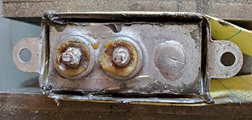
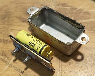
Photos below show the tub rebuild process on a #1574 dual 0.1uf 400vdc capacitor. The other types of tubs used in the RU-16 were rebuilt using the same procedure with slight variations. Tubs #1572 have the terminals on the top of the tub and the bottom plate is just a flat cover soldered in place. These are easier to rebuild since the new caps can be fit into the tub, soldered to the terminals, etc. and all that's left is to install the bottom plate. Tubs #3562, #1573 and #1575 use 0.5uf capacitors that are fairly large but 400vdc types will fit into the tubs, with the exception of #3562 which must use 200vdc types. Tub #1573 is a very tight fit using a 0.5uf 400vdc cap but it will fit in although I did have to use an insulating piece of fiber board on the bottom plate since it was right up against the capacitor body. 


1. Slices around inside edges made with Dremel Cut-off Wheel


2. Bottom plate pried up to show black fiber insulators and bee's wax inside


3. Bottom plate and fiber insulators removed showing dual capacitors inside


4. Tub, insulator and bottom plate cleaned and ready for new capacitors

5. New capacitors installed on the bottom plate with fiber board insulator between. The outside foil leads aren't sleeved since they connect to the tub body when the bottom plate is soldered in place. Hot leads going to the terminals are sleeved.

6. The bottom plate is soldered in place. I used a 250W Weller soldering gun and that provided enough heat to run a bead of solder around the seam between the bottom plate and the tub body. The finished rebuilt #1574 dual 0.1uf 400vdc capacitor is now ready to reinstall into the receiver.

 
Post-rebuild Performance - The tub capacitor rebuild has corrected the electronic problems in the RU-16. The AGC now does function correctly with strong signals reducing the RF amplifier cathode current down below 10mA. The average strength signals will have some AGC action with the RF amplifier cathode current at about 15mA. No signal AGC will increase RF amplifier gain to the maximum with about 25mA of cathode current indicated. Also, now the INCREASE OUTPUT does adjust the AF output level in AUTO although most of the time on lower RF frequencies the control is just about at the minimum setting.

Tuning backlash is significant and makes fine tuning fairly difficult, especially in CW or SSB. Even using the direct drive doesn't help all that much. Actually, using the Receiver Tuning Head allows easier tuning despite its more significant backlash (due to flexing in the drive cable.) This is probably because of the better leverage using the crank for tuning. A good lubrication of the tuning gearbox all but eliminated the backlash - the procedure is further down this page.

Listening on 80M with the Q-G range coil provided reception throughout the 80M band. Sensitivity was very good but selectivity was fairly broad. Ultra-strong SSB signals (local station when received using a full-size matched antenna) will over-drive everything (in MANUAL with BFO on) and even reduction of the RF sensitivity doesn't seem to help. A short antenna will improve the RU's ability to handle these types of signals (it was never designed to receive strong SSB signals anyway.) CW signals are no problem. AM signals do very well using AUTO and the AGC is easily able to keep up with the normal type of QSB. It's interesting to observe the TEST METER (monitoring TRF amplifer section cathode current) swing around but the audio output remain constant. 80M AM stations that run "communications" audio are easy to copy while "mock-broadcast audio" signals are very difficult to copy. Adjacent frequency QRM can be a problem and one would think going to MANUAL would help but actually AUTO gives the best copy on most AM signals. Range H coil set also covers 75M even though its range is shown as 4000kc to 6000kc. The lower end of the tuning range extends down to about 3850kc, allowing most of the military-radio AM nets to be tuned in using this single range coil set.

Using the L-N range coil on 40M with a resonant antenna provides plenty of signals. Rarely are ultra-strong SSB signals a problem and a matched or resonant antenna seems to be necessary for decent sensitivity on this band. SW on 49M is very good although sometimes the AM reception in AUTO can be very broad allowing stronger stations, like Radio Havana, to dominate a wide portion of the band. Detuning the antenna (use the trimmer control) can help with ultra-strong signals. Utilities stations in the 8mc region can be received but the two marine beacons SVO (Athens) and TAH (Istanbul) are very difficult to receive requiring a resonant antenna and good propagation.

The Range E coil was installed in the RU-16 when I got it and it has the same serial number as the receiver. This coil set tunes the upper section of the AM-BC band and 160 meters. With a large antenna (not a ham band antenna but an end-fed wire 160ft long) the signals on the AM Broadcast band are way too strong. AUTO will keep the RF gain in control but signals have a broad bandwidth. Better results on AM-BC using a 20 ft long wire. A resonant antenna can be used on 160M if QRM isn't a problem otherwise a small "receive only" antenna might help (like a shielded magnetic loop antenna.)

Using the K range coil is a real challenge since it pushes the RU up to its highest frequency coverage. SW reception on 31M and 25M is okay, 10mc WWV is easy to receive, some 30M CW signals can be received. Above 10mc, the sensitivity drops dramatically. A resonant or matched antenna is a real necessity with the K coil.

To wrap it up, below 5mc, signals are very strong and the antenna isn't too important. Any of the AM-BC coverage works very well with a short end-fed wire. Below 500kc works well depending on the antenna used and local noise. A loop works best on MW-LF. Above 5mc, signals are beginning to drop in strength and a resonant antenna becomes much more of a necessity as the frequency is increased. Don't expect high fidelity from the single triode Audio Output tube listening via a 600Z headset. The RU-16 was for radio reception in an in-flight aircraft via phones, so if you can easily and loudly hear the received signal, then the receiver is doing its job correctly.


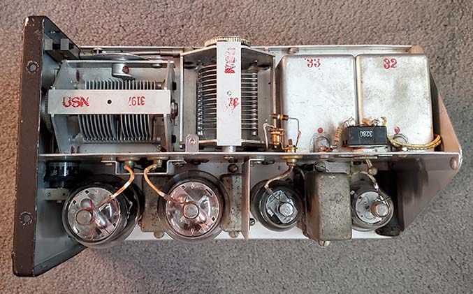
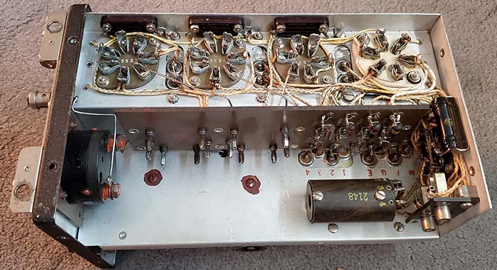
photo above
: Tub caps installed in the RU-16. The five tubs mounted on the chassis side are obvious. Note that between the tube sockets, the terminals of five other tubs can be seen. Also, to the far left is another tub mounted on the rear panel. Eleven tubs total. Originally, each tub terminal was coated with sealing wax first then the wires installed and then a drop of bee's wax after wiring. I haven't done that,...yet. I wanted to test the operation of the receiver first and then, maybe later, I'll pull it out of the cabinet and apply the wax coatings to complete the rebuild.

"On the Air" Selectivity

Why the RU Receivers are so Broad Banded - First, and most important, the RU-16 isn't a ham receiver. It wasn't designed to function as a "ham band receiver." It was NEVER intended to be operated anywhere in a congested part of the RF spectrum. Since the RU-16 was usually going to be installed into a single-seater aircraft, in most cases, the radio gear was located behind the pilot's seat and was "pre-flighted" so the pilot wouldn't need to do much radio adjusting and could mainly fly the airplane. But, the pilot might have to change the operation of the radio gear once in a while. Sometimes this was to change from communications to reception of a homing signal using ZB-type VHF converter. In single-seater installations, the radio gear was adjusted using remote function cables and remote tuning heads. This required simple-to-operate and easy to adjust radio gear. The last thing the pilot needed was to be searching for signals on a super-selective radio receiver that was difficult to tune because of adjustments that were made through remote cables and tuning heads,...and trying to accomplish that all while flying the airplane with the possibility of being shot at. So, that's why the broad bandwidth for the RU receivers,...it was designed that way because generally the receiver wasn't going to be tuned while the aircraft was in flight so it had to be broad banded enough to still copy signals if they were slightly off frequency. Also, if tuning was required, it would have to be fast and easy for locating homing beacon signals or communication signals.

How to Use the RU Receivers on the Ham Bands - Well then, here we are trying to use a WWII aircraft receiver on modern-day 75M phone. To say that you'll hear several stations at the same time is not too much of an exaggeration. For example, when using the OP coil you can hear the entire 630M band all at once! (well, it is only 9kc wide.) To gain maximum selectivity without modifications will require using a smaller antenna for receiving. The large transmitting antenna will have way too much response and pick up way too many adjacent signals (we do want to use a large transmitting antenna since the power output from the GF-11 is QRP-level.) The small receiving antenna will have a little more selectivity and won't respond well to weak signals but most 75M mil-rad nets are usually comprised of pretty strong signals. Operate the RU receiver in MANUAL. This keeps the sensitivity to just what you need and will reduce weaker QRM. Off-frequency tuning usually doesn't work for dodging QRM because of the wide bandwidth. Probably what works best is to avoid using the RU-GF station during high activity times. For example, the Vintage Military Radio Net starts at 0730hrs on 75M and at first the band is pretty busy but by 0830hrs there's virtually no interference and the conditions are still good enough to use a QRP station like the RU/GF. It's best to operate the RU/GF combo on a mil-rad net where the participants are used to hearing low power field sets, portables and lots of different types of aircraft gear. When the RU-GF station is working well you usually won't have too much trouble with the GF's low-power signal being heard. It has a good punch to the audio when adjusted correctly. The problem will be adjacent frequency interference in the RU receiver. But, if you're prepared and operate during low activity periods, the RU is more than sensitive enough for 2X communications. CW is totally different with very few problems. This mainly because there is so little CW activity these days. Also, a help is that the GF-11 has about 20 watts output power on CW.

More RU-16 Info

RU-16 Coil Sets - I have the following RU-16 coil sets:

Single Range Coil Sets - CW-47069 - Range E - 1330kc - 2040kc (this coil covers 160M band, top of AM-BC band - original to the receiver with matching serial number - looks NOS, was installed so no container)

                                       CW-47072 - Range H - 4000kc - 6000kc (this coil extends somewhat into top of 75M band, covers 60M, 5mc WWV, portion of 49M SW band - looks NOS with container)

                                      CW-47075 - Range K - 9050kc - 13575kc (this coil covers 30M band, 10mc WWV, 31M SW band - NOS coil set with container)

Dual Range Coil Sets - CW-47105 - Range O - 195kc - 290kc  &  Range P - 290kc - 435kc (this coil needs to be rebuilt, it's in very poor condition with a broken range switch - no container)           

                                    CW-47107 - Range Q - 540kc - 830kc  &  Range G - 3000kc - 4525kc (this coil covers 80M band in high range, bottom of AM-BC in low range - NOS coil set with container)

                                    CW-47112 - Range L - 400kc - 600kc   &  Range N - 6000kc - 9050kc (this coil covers 40M band, 49M SW band in high range, 630M and bottom of AM-BC in low range - NOS original box w/container)

Range Switches on Dual Range Coils - Each Dual Range coil has five coil assemblies each of which has an internal switch for changing the tuning range. These switches are very delicate and break easily if mechanically misaligned. The rotor part of each switch is a small circular fiber board piece with two embedded brass contacts. The contacts are cylinders that protrude through each side of the fiber board rotor thus creating a continuous path on each side of the fiberboard rotor. There is a spring-metal contact frame surrounding the rotor with each side contacts on the frame connected to coil wires. When the switch rotor is in the CCW position, the low band coils are connected into the circuit and when the rotor is in the CW position then the high band coils are connected into the circuit. After setting for decades, the brass contacts in the rotor oxidize somewhat. Usually, the Range Switch contacts will clean themselves of the oxidation with a few switch operations. If the oxidation can't be cleaned in this manner, then disassembly of each coil section is necessary to clean the contacts. This disassembly requires removing the Range Switch shaft (made of garolite - somewhat like fiberboard.) To access the switches requires removal of each coil assembly from the housing and then removal of the lower shield cover. Be sure to observe how the coil assemblies are mounted before removal. Be sure to keep all of the rotors in the same position after cleaning so that the square Range Switch shaft can be reinserted without misalignment. Any other problems involving the coils might require further disassembly. This will require unsoldering the wires to allow the coil to be removed from the shield can on the low range coil. Most of the time, the coils are okay but poor storage conditions could cause oxidation problems. The most common problem with the dual range coil sets is oxidized switch contacts followed by broken fiber board parts. When doing the reassembly, don't tighten the two screws that mount each coil assembly to the housing (ten screws total.) With the coil assemblies somewhat loose, plug the coil set into the receiver. That will align the assemblies to the mating pins in the receiver. Then tighten the coil assembly mounting screws.

NOTE on Coil Sets
: My O-P Range Coil is in really rough condition. It was the first coil set that I bought for the RU-16 (and it was only $10.) But, I've learned a lesson from its purchase and from my subsequent coil purchases. If the coil set is NOT in its original storage container and if the coil panel is dented, with paint missing, with the coil assembly cans bent and misaligned,...well, that coil set has been used, abused, thrown around and treated carelessly. The dual range RU coil sets are delicate and won't survive that type of treatment. The fiberboard parts of the switch mechanism will break easily if the coil set is thrown or roughly treated. My O-P coil has a couple of the fiberboard switch rotors broken which prevents operating the range switch. They can be repaired but the O-P coil set would still be in "rough-looking" physical condition. After the purchase of the O-P coil, I've subsequently only purchased RU-16 coil sets that are NOS in their original metal containers. That would be the Q-G and L-N dual range coil sets and the K and H range coil sets. These NOS coil sets all operated perfectly in the RU-16 receiver. Single range coil sets are more durable but still shouldn't be in abused condition for best performance.

BFO Adjustment - All of the coil sets do require readjusting the BFO since the original adjustment was for 1000hz over the tuned RF. This is a little higher than I like and the adjustment is easy. There's a snap cover on the coil panel over the rearmost coil assembly. Remove the snap cover and the BFO adjustment is a .250" hex trimmer that's fairly deep into the coil assembly. I use a plastic .250" hex alignment tool for the adjustment. Dual range coil sets have two snap covers since there are two BFO adjustments. I adjust the BFO for about 600hz above the Tuned RF. The 1000hz was the Navy standard for CW reception. It does have advantages for CW reception but it makes demodulating SSB difficult and also for MW NDBs it's too high. 600hz is a good compromise for all types of reception.

Lubricating the RU Gearbox - I don't think this procedure is covered in the manual,...it isn't in the version I have anyway. My gearbox was pretty dry so I'm sure it had not been lubed,...since 1941 anyway. The dial has to be removed so first remove the small screw that determines the dial position on the hub (it's right next to the hub nut.) Then remove the hub nut. This will require a 5/8" socket and a socket wrench. It's tight but it will loosen easily using a socket wrench. Be careful not to scratch the dial or the nut. Next, there are six small screws that mount the gearbox cover. Two are fillister head screws and four are flathead screws. When these screws are removed, the gearbox cover can be dismounted. Now the entire gearbox can be accessed. There's not very much in there,...the main drive gear, the worm gear and worm gear shaft. If there's anything inside, like dried grease, dirt, rust, clean this up. Then apply clean grease to the worm gear and the drive gear. The drive gear isn't a split gear so applying grease there is okay. Use 10W machine oil and apply a drop or two to the worm gear shaft bearing and to each of the spline drive inputs. Run the tuning back and forth a few times, reapply some grease if necessary, then clean up the excess grease and remount the gearbox cover. Remount the dial - be sure to center the dial locating hole with the threaded hole in the hub to assure calibration is correct, then install the hub nut. Tighten the hub nut and then install the locating screw. That completes the lubrication procedure.

As mentioned, my RU gearbox was dry so this lubrication really helped in the smoothness of tuning by eliminating the minor mechanical "sticking and grabbing" that made tuning CW and SSB signals difficult and also by reducing the backlash by about 80%. The grease type isn't too important. Good quality wheel bearing grease is probably fine. I used sodium-based fibrous yellow grease for its damping ability and also it adheres to the gears better.

photo right: Actually the gearbox on a BC-AL-229, aka: the Army "RU" receiver. Gearbox is identical to the Navy RU receiver. This one is "as found" with dried grease and dirt plus some rust. Note the dial locating screw hole on the hub at 10 o'clock. Drive gear is "pinned" to tuning shaft so dial locating screw is normally always in the proper relationship to the tuning condenser.


Getting the GF-11 Operational

Problems - Although the GF-11 was an excellent condition example on the outside, inside it was the victim of a hamster hacker sometime in the past. The Modulator/AF Osc tube, a type 89, had been replaced with an octal base type of tube (probably a 6V6, it was missing when I got the transmitter.) Although the PA tube sockets weren't changed, the PA tubes were now type-1625 instead of the original type-837. Like a lot of transmitter mods, this was a hamster attempt to increase the power output capabilities of the GF-11 from its original maximum of 15 watts up to possibly 50 watts output. Since the PA output was increased 300%, the AF Mod tube also needed greater power than the 89 was capable of, so the change to a 6V6. The result of this mod was that the original WE six-pin tube socket for the 89 was gone. Several wiring changes had been incorporated for the new Mod/AF Osc tube and PA tube change. Also, several resistors were replaced with different values and power ratings to handle the 1625 tubes and increased power level. The further I got into the GF-11 the more I discovered that almost every circuit had some changes. Luckily, no holes were drilled so everything could be put back to original but it did require detailed examination of the transmitter and scrutinizing the wiring diagram-layout with regular references to the parts list for component values and to the schematic for component function.

De-mod'ing the GF-11 - I couldn't find a six-pin tube socket that was like the WE-CINCH type so I originally intended to use a fiber board socket but it didn't look very durable so it was replaced with a ceramic version. Before getting too far into this GF-11, I wanted to check the three transformers for proper DCR of the windings since the intent of the mod had been to increase the power 300% but these transformers are for screen modulation and sidetone so, even with the PA increase, they probably didn't have their ratings exceeded. The three transformers all tested okay with the correct DCR measured. I checked all of the original resistors and all measured within 10% tolerance. The capacitors were given a limited test to make sure they weren't shorted (this was before I knew that rebuilding is mandatory on ALL of these WE tubs - RU-16 and GF-11 - both.)


photo above: Top of the GF-11 chassis. Air variable 3197 looks like it has two rotors but only the front rotor moves. The back rotor is a padding capacitor that's "factory set."

I removed the octal tube socket and replaced it with an E.F. Johnson ceramic six-pin tube socket since it had the same type of tube pin contacts as the CINCH sockets. It appears "incorrect" but if an original CINCH socket is ever found (or a GF-11 parts set,) I'll replace this ceramic tube socket. I then began to resolder the original wires to the correct tube pins but noticed that a lot of wires were missing when compared to the GF-11 wiring diagram. Throughout the transmitter many of the wires were cut off and totally removed. There were about five newer gray colored plastic insulated wires that weren't original that had to be removed. The HIGH-LOW Sidetone switch had the shunt resistors removed and the wiring changed. Initially, I had thought that this GF-11 only had minor mods but I ultimately discovered that it was extensively modified to allow the use of 1625 tubes in the PA (and the 300% power increase.) I'm pretty sure the transmitter was never operated after the modifications were incorporated. In fact, I'm pretty sure it would never have worked very well anyway.

This ended up being a fairly extensive reworking job to bring the GF-11 wiring back to original and to have the replaced wiring look completely authentic (I used vintage wire for the rebuild.) Note in the photo left that the rightmost tube socket is very apparent as a different style than the others that are WE-CINCH sockets. Although this socket is functional, if I ever find the correct type of WE-CINCH socket, I'll replace it.

The photo to the left also shows the rebuilt tub capacitors installed. Also, all incorrect resistors have been replaced with the proper values and proper type. Only the tube socket "stands out" as an obviously non-original part.

Making an Army Transmitter Control Box Work Like a Navy Transmitter Control Box

I never have been able to find a Navy CW-23097 GF-11 Transmitter Control Box. I was fortunate that WA6OPE had a BC-AN-232 that he was willing to donate in the hopes that I could modify it to function like the Navy CW-23097. The following was the process of conversion,...

BC-AN-232 - Signal Corps - Transmitter (Radio) Control Box - July 10, 2021 - WA6OPE donated a BC-AN-232 Signal Corps version of the Transmitter Control Box (called a "Radio-Control Box) that he had found in one of his junk boxes. This control box is similar to the Navy GF-11 box but was for the BC-AL-230 transmitter, an Army version of the Navy GF transmitter.

In going over the BC-AN-232 control box, it has the same 8 pin box connector, a similar mode switch, the same types of MIC and KEY jacks, the same large push button key and externally it looks very much like the CW-23097. But, that's about where the similarity ends. The BC-AN-232 control box doesn't have the RADIO, ICS-1, ICS-2 toggle switch, it doesn't have the neon glow lamp, the mode switch construction is slightly different and the box receptacle is wired almost entirely differently when compared to the CW-23097 GF-11 control box. I don't want to drill any holes or try to externally modify the Army box to be like the Navy box for two reasons. First, it would never look right. Second, I don't want to destroy the BC-AN-232 just in case it might be needed for a future project. What will be done to the BC-AN-232 will be reversible. Also, I haven't given up on finding the proper CW-23097 Navy GF-11 control box (but it's seeming like no CW-23097s are around.)  >>>

>>>  To preserve the BC-AN-232 I have to limit the GF-11 functions to what components are in the Army box. The ICS selection switch circuit can't be used which really isn't a problem since that was for intercommunication between the pilot and the radio op. I won't have the neon glow lamp that illuminates when the transmitter has high voltage applied. It's a really nice feature but not essential to operation. The mode switch appears similar but is made up of four quadrants where the CW-23097 mode switch only uses three. Luckily, the Army switch has three switch sections that are exactly like the three needed for the GF-11 operation.

The easiest procedure is to rewire the Army box per the Navy box schematic. The limiting resistor for the neon glow lamp, just won't be installed and there won't be a connection to that pin on the connector (pin 40.) Wiring for the receiver muting in ICS-2 will be wired directly to chassis as if the box was switched in the RADIO position (chassis ground on pin 42.) Most of the other changes are rearranging the connections to the box connector although a series 200 ohm resistor has to be added for the mike input on pin 41.

The end product will provide the GF-11 with mode selection of CW, MCW and VOICE. The MIC and KEY jacks will function normally with the tip of the MIC jack and the CW key operating the PTT Transmit line. The large button CW key will function normally. Though BC-AN-232 will be substantially changed internally, it could be put back to original and externally there wouldn't be any changes from original. This example of the BC-AN-232 was "well used" with obvious wear so I'm not compromising a "mint, NOS" example. 

Maybe a Navy CW-23097 will show up before I get started,...but I doubt it!  I waited two months, looked on eBay, asked guys that had GF-11s for sale, ads on QTH,...nothing found!     Sept. 9, 2021,...I finally had to get started on the mod,...

Connector Reconnect - The following changes are required for the BC-AR-232 to function as the CW-23097

     BC-AN-232                          CW-23097                    
           pin 51              remove wire               pin 41 - MIC ring cnx jack thru 200 ohms*
           pin 40              remove wire               pin 42 - tie to chassis to ground 1642 cathode
           pin 42              move wire to              pin 48 - Switch - Voice/MCW function
           pin 41                      "                          pin 49 - Switch - CW function
           pin 48                      "                          pin 50 - PTT line
           pin 50                      "                          pin 51 - Switch - Voice
           pin 52              no change                    pin 52 - Chassis Ground
           pin 49   no wire, was relocated to      pin 40 - no connection since no neon lamp

* 200 ohm resistor is in series with the MIC jack ring to pin 41 on the CW-23097. This resistor wasn't used in the BC-AN-232. Resistor used was actually 180 ohms (standard value.)

The CW-23097 also had a 200K resistor from pin 40 to the neon lamp which isn't going to be used for this change. The neon lamp B+ indicator wasn't used on the Army version and would require hole drilling to mount a neon lamp which I wanted to avoid.

There are four quadrants to the switch used in the BC-AN-232. Only three switch functions are necessary for the CW-23097.


BC-AN-232 Transmitter Control Box


Inside the Control Box after conversion to CW-23097. Shows the CW key quite well. Note 180 ohm resistor on mike input.

 Pin 42 is tied directly to ground in this change although in the CW-23097 this function was part of the RADIO, ICS-1, ICS-2 switch (which the Army version doesn't have.) This connects the RU-16's 1642 cathode to chassis (through the Junction Box) which is like having the ICS switch in the "RADIO" position. The PTT line is routed directly to pin 50 but in the Navy box the PTT line was routed through the RADIO, ICS-1, ICS-2 switch since you didn't want the transmitter keyed when using the intercommunication function.

More Cables Needed

Two more cables need to be built,...the 3162 cable connects the GF-11 transmitter to the Junction Box. This is a nine conductor shielded cable that I'm building from the "too short" eleven conductor cable that was originally going to be for the RU-16. The two plugs RU-16 plugs have been removed and all that's necessary is to install the two correct GF-11 plugs (which I have.) To have the cable and shield fit into the shell exit fitting better I took the entire cable apart to remove the two unnecessary wires which reduced the diameter just enough to have a snug but moveable fit of the shielded cable through the fitting.

The second cable is the 3148 cable that connects the Transmitter Control Box to the Junction Box. This is an eight conductor cable but at this time only seven of the conductors are actually going to be used. Since there might be a possibility that a CW-23097 might turn up in the future, I'm building this cable so that it can be used with my modified BC-AN-232 Transmitter Control Box but it will also work if the proper CW-23097 ever shows up. The next problem with the 3148 cable is the proper plugs. All I have are two substitute #37 plugs. These plugs have the correct bakelite plug fitting and the proper spring button lock but the metal shell doesn't have a rear exit for the cable or the rear cable fitting for exiting the shell. Luckily, the shell can be modified by drilling a rear exit hole and installing the proper fitting that can be removed from a "junk" plug to build-up a complete proper plug. Fortunately, the two #37 substitute plugs can be modified to build a complete 3148 cable.

Sept. 17, 2021 - Completed building up cable 3162. This cable is 24" long.

Sept. 18, 2021 - Cable 3148 required using two #37 substitute plugs. These plug had the correct bakelite plug, the spring button and a shell. However, the shell didn't have the cable exit fitting or even a hole. The required hole is .625" in diameter. I used a 5/8" Greenlee punch to make the rear exit holes. I salvaged the correct cable bushings from derelict plugs. The finished modified #37 plug looked and functioned like the correct eight-pin plug required for the 3148 cable.

A very common problem found on many of the plugs used for the RU-16 and GF-11 was a "stuck" bakelite plug that couldn't be removed from the aluminum shell. The method I use was to find a solid metal rod about 3/16" diameter and about 4" long. Place the plug on a machinist's vise very carefully so that the aluminum edge of the shell is supported but the bakelite plug can pass through the open jaws of the vise. Insert the metal rod through the rear of the plug shell. Be sure the metal rod is resting on the bakelite and not a socket pin. Now tap the metal rod with a ball peen hammer. Once the bakelite plug starts to come out you can center the aluminum shell edges and make sure the bakelite plug just fits through the jaw opening. Keep tapping until the plug comes out. Now that the plug is out, the two pieces have to be "sized." I use a flat, diamond-surface file to remove some of the bakelite material to reduce its diameter. I use a round metal file to clean and enlarge the inside diameter of the shell. Not very much material has to be removed for the two pieces to fit correctly. Once the fit is correct, then the plug can be used for the cable building.

One plug needed "sizing" for the 3148 cable but the second plug was okay. Cable 3148 is 22" long when completed and tested.

GF-11 Tub Capacitors

After all of the problems with the RU-16 that were caused by these 80+ year old tub capacitors I'm rebuilding these tubs before I ever apply power to the GF-11. I'm using different manufacturer capacitors for the 0.5uf. These are 630wvdc but they are much smaller in diameter than the 400 volt caps I used for the RU-16 tubs. These new ones may be smaller in diameter but they are quite a bit longer. Tight fit lengthwise and sleeving the hot lead will, as always, be required. The unusual #3563 is a dual electrolytic capacitor tub with the two electrolytic capacitors being different values. Lots of room in the tub since modern electrolytic capacitors are so small. Also, the values of electrolytic capacitors aren't all that critical when used for filtering purposes. So, I'm using a 25uf in place of the 20uf and I'm using a 10uf in place of the 5uf. Working voltage specs are 50 volts DC for all electrolytic capacitors used (also, not critical if it's a higher rating.)

#1575 - (2) 0.5uf   300wvdc paper capacitor - There are two #1575 tubs in the transmitter
#1574 - (2) 0.1uf   400wvdc paper capacitor - There is one # 1574 tub in the transmitter
#1573 - (1) 0.5uf   300wvdc paper capacitor - There is one # 1573 tub in the transmitter
#3563 - (1) 5uf  25wvdc electrolytic, (1) 20uf  25wvdc electrolytic - There is one #3563 tub in the transmitter
Polyfilm Capacitors Required:                                  Electrolytic Capacitors Required:

0.5uf  630wvdc polyfilm - 6 required                25uf  50wvdc - 1 required (mic filter)
0.1uf  400wvdc polyfilm - 2 required                10uf  50wvdc - 1 required (mod cath. bypass)
Total of 8 polyfilm capacitors required                Total of 2 electrolytic capacitors required

Since there are only five tubs used in the GF-11, I decided to go ahead and dismount all five and rebuild them all at the same time. Although the manual's assembly drawing is very good, I made my own notes for reassembly. The stacked assembly of three tubs isn't shown very well on the manual's assembly drawing and also I ended up adding a few coding marks on some of the wires to ease rewiring the rebuilt tubs.

I used the same "tub rebuilding" procedure as shown above in the RU-16 section.

Sept 20, 2021 - Performed the first step for rebuilding the five tubs which is to remove the bottom plates, remove the old capacitors and clean up the pieces to prepare for installation of new polyfilm and electrolytic capacitors.

Sept 21, 2021 - Only had time to rebuild one #1575 tub. I neglected to check the mica insulators and clean that area really well. When the #1575 tub was fully assembled, one capacitor measured correctly but the other cap was shorted to case. I had to unsolder the bottom and in checking I found a tiny solder bridge on the inside of the mica terminal was causing the short. The two insulators were thoroughly cleaned and inspected. Then the two caps remounted and checked for value. Then the bottom cover was resoldered in place. A recheck showed the correct values for both capacitors.

Sept 22, 2021 - Rebuilt the remaining #1575 tub. Rebuilt the #1574 and the #1573 tubs. All three tubs tested for correct values.

Sept 23, 2021 - Rebuilt #3563 tub and tested for value. All five tubs reinstalled into the GF-11. All wiring to the tubs verified with the manual wiring diagram.

Testing, Troubleshooting, Repair and Calibration of the GF-11

To actually apply power to and operate the GF-11 requires all station pieces be interconnected. When the RU-16 and GF-11 along with the Dynamotor, the Receiver and Transmitter control boxes, the Junction Box and the Antenna Relay Unit are all plugged in to the Junction Box receptacles then the following should happen:

Turning on the RU-16 via its control box will apply power to all tube heaters in both the RU-16 and GF-11. The +HV or bias voltages won't be applied to the GF-11 since essentially the station is in the "receive mode." Plate voltage will be applied to the Mod/Tone tube in GF-11 since operation of the ICS might have been required.

When the GF-11 transmitter control box is in CW, if the sending key is pressed the following happens: The relay inside the Junction Box switches to "transmit," the B+ voltage is removed from the RU-16, the Antenna Relay Unit changes to "transmit," +HV and bias voltages are applied to the GF-11, the Mod-AF Osc tube provides a sidetone and a CW signal is applied to the antenna. Releasing the key returns the system to the "receive mode."   >>>

>>>  When the GF-11 is in VOICE or MCW then a constant carrier is present. The same obvious functions happen as in CW with these exceptions: The Mod-AF Osc tube becomes the speech modulator and the sidetone function is disabled, PTT is controlled by the mike button. In MCW the Mod-AF Osc becomes a 1000hz tone signal for modulation and the sidetone function also operates.

Generally, maximum RF current is in the CW mode with MCW being slightly less and VOICE being the least amount of RF current. The output power is highly dependent on the antenna load impedance and how well matched the inductor tap is set on the plug-in coil. About the maximum RF current achievable is 1.0 amp although that value is highly dependent on the antenna characteristics - a very low Z antenna for that much current. Typical would be .4A to .5A into ~50 ohms in the CW mode. 

The actual antennae used with the GF-11 would have been highly reactive and the impedance would vary quite a bit. On an single-seater airplane a small wire antenna from the radio set up to the tail was about 15 feet long and would have had very low XL and higher XC with probably a low impedance. A large airplane's trailing wire might have had high XL and lower XC and been a fairly high impedance. Since the GF-11 will have to work into a standard ham antenna, a 50 ohm dummy load is going to be used for test and set up along with an inline wattmeter. Other test equipment will be a Tektronix oscilloscope, GR digital frequency counter and the lab receiver (Siemens E-311.)

Generating RF

TESTING - Sept 25, 2021 - I had to rearrange the equipment with the Junction Box at the rear to have enough room for the GF-11 and its control box. The GF-11 was not installed in its case since I was pretty sure some adjustment of the padding condenser was going to be necessary. Also, adjustment of the plug-in coil L was going to be necessary. In the manual there is a chart that gives the approximate placement of the adjustable coil tap. The chart references the lower end of the coil and the number of wire spaces necessary for proper placement of the sliding contact. Coil winding space 25 was interpolated from the data provided in the manual. With power applied, a small movement in the RF amp meter indicated something was happening when the key button was pressed. I connected a digital frequency counter and found that the frequency was at 4.2mc rather than 3.974mc. I set the dial to the lowest reference point which was 3.650mc at dial setting 5.40. I loosened the nut on the padding condenser and increased the C until the frequency out was at 3.650mc. The padding condenser nut was then tightened. This isn't an ultra-critical adjustment but is provided to calibrate the tuning dial to the coil chart data and once set it remains fairly accurate for all coil sets. Additionally, there is a C trimmer accessible when the transmitter is in its case that allows further adjustment of the tuning C. 

I next adjusted the tuning dial to about 14.0 for a frequency of 3.974mc, which was determined again by interpolation of the chart on the coil set. A slight adjustment of the dial was all that was necessary to have the desired operating frequency. Now the transmitter was keyed and the Antenna Tuning adjusted for maximum RF amps, which was just about .5 amps into a 50 ohm R dummy load. I listened to the transmitted signal on the lab receiver and it was a good sounding CW note. I connected a W4 RF wattmeter and measured 18 watts output, which is higher than the manual estimate of 15 watts. Actually, .5A into 50 ohms calculates to 12.5 watts, so the wattmeter accuracy might be off or maybe the Thermocouple RF amp meter is off. Will verify later with a known accurate wattmeter. At any rate, the GF-11 was performing as expected on CW.  >>>

>>>   Next was VOICE. I connected up the RS-38 microphone and switched to VOICE mode. Pressing the PTT button, the GF-11 produced a sidetone and behaved like the GF-11 was in MCW. I switched to MCW and there was no change. I rechecked the wiring that I had done in both the control box and the GF-11 but couldn't find any errors. I decided to measure whether switching to VOICE really did ground the sidetone pin on the control box and it didn't. Several operations of the mode switch would sometimes show continuity to ground but most times it would measure open. I used a scraping tool and DeOxit to clean all three segments of the mode switch. This got the sidetone section to actually switch to ground in VOICE. Connecting up the control box and powering up the GF-11 in VOICE I now had AM modulation and the sidetone was properly disabled. Power output on VOICE was about 8 watts on the wattmeter but the RF current was on 0.2A which calculates to 2 watts. Thermocouple RF amp meters do tend to be most accurate at 50% to 75% of FS and generally aren't very inaccurate at the low end of the meter scale,...hopefully the W4 wattmeter is the more accurate of the two measuring methods. I did connect up a second W4 wattmeter and it read exactly the same as the first W4. I'm afraid that the Thermocouple RF Amp meter is a little stingy when only reading about 3% of FS (mechanically, the scale isn't linear.) I'm going to go with 18 watts CW and 8 watts carrier power in VOICE which should provide about 12 - 15 watts output peak.

I tried three microphones, the RS-38, a newer Shure 102-C and a new electret type mike. The RS-38 had very good articulation but the response was fairly low with modulation levels that looked like maybe 50%. The Shure 102-C had much more response but tended to pickup dynamotor noise when not being talked into. The modulation level looked like about 80% with the Shure. The electret had about the same response as the Shure but sounded like it had an echo. With all three mikes, the audio did sound strong with much better modulation than the 'scope showed but that may have been due to the setup for testing (not using shielded cables for the 'scope input.) In the "Installation and Operation" section of the manual the text mentions that CW is the most effective mode followed by MCW and VOICE is the least effective mode.  NOTE: Once the RU/GF station was installed in the shack and working into an actual antenna with a "known" 'scope waveform monitor, the GF-11 audio waveform looked normal and the modulation level looked at least 80% with the RS-38 mike and an easy 100% with the Shure mike.

Setting Up the Station and Getting "On the Air"

Setting up - October 5, 2021 - I decided to use a small oak office desk as a basic structure for the station. The desk top is only 43" across. I needed to build a "riser" that would allow having the cables and the Junction Box located underneath the riser. I used an old lumber-core table for the top of the riser and similar lumber-core material for the verticals. Also, another vertical was placed at the rear for mounting the Junction Box. The old office desk had a dark green rubber-like linoleum top so I painted the riser dark green to match (well,...the paint was a little more olive green than I thought but,...close enough.)

The Station Plan - The plan was to actually have two functional WWII Navy airborne radio stations. The RU/GF station on the left side of the riser. On the right side of the riser would be the Navy ARB receiver set up to run with the Navy Collins T-47/ART-13 on the right side of the desk. BUT, sometimes plans have to change. Especially when a receiver like the ARB is involved. I did have the ARB set-up and did attempt to use it "on the air" but the ARB is really unable to cope with normal ham band activity. The ARB was designed for pilot operation in a single-seater WWII aircraft. It purposely was designed to have a very broad IF bandwidth to make finding homing beacon signals easy. Even in SHARP, the IF bandwidth must be at least 10kc wide. Today, on the ham bands, the ARB is sensitive enough but the IF bandwidth leaves the user at the mercy of QRM from just the normal ham band adjacent frequency activity. An adjacent frequency signal 6kc away that wouldn't cause any QRM in a different receiver will reduce any desired signals on the ARB to incomprehensibly. So,...the new plan is to install a different WWII airborne radio transmitter and receiver. Since I had an early WWII aircraft setup with the RU-GF station, I decided to have a late-WWII station,...the ARC-8. I used a USAAF ART-13A along with a BC-348-R, a combination that would have been popular at the end of WWII.

Back to the RU-GF station,...as for the desk top, the left side will be used for either a LM CFI or for mike and key storage. The RU-GF Junction Box has its original mounting plate as does the RU-GF Antenna Relay Unit but the mounting plates for the dynamotor, the receiver control box and the transmitter control box were all missing. While making replicas wouldn't be too difficult, I'm just going to mount the various boxes with small wood screws and black Garolite washers utilizing the slide-clip holes. The receiver control box required a small wooden extension so the box would be at the proper height when mounted.   >>>

>>>  With the Junction Box mounted at the rear of the riser then the +14vdc Lambda power supply was mounted on the floor (at the back of the foot well of the desk) and the Dynamotor was mounted next to the power supply. Cable 3156 from the Dynamotor to the Junction Box was barely long enough to span the distance. All other cables were also "just long enough." If I were doing this again, I'd make all of the cables at least 12" longer than what I measured. I have to redo the cable for the Test Meter since it is way too short to reach the GF-11 and is only long enough to use with the RU-16. Luckily, it's only a two conductor shielded cable.

October 10, 2021 - The RU-16/GF-11 station is completely set up and operational. It works great into the 135' tuned inv-vee antenna with the Johnson Matchbox providing a 50Z ohm match. Probably because of the difference between the pure R of the dummy load and the slight reactance of a true antenna and matching device, the transmitter output is almost 0.6A on the RF amp meter and shows 20 watts on the W4 wattmeter in the CW mode. In VOICE the output is now showing 0.3A on the RF wattmeter with the W4 wattmeter showing 11 watts carrier power. Watching the oscilloscope that monitors the RF output, it's very apparent the positive modulation peaks are much higher than the carrier level which indicates that the peak power is probably around 15 to 20 watts on VOICE. Listened to the transmitted signal on another receiver using 'phones and the audio quality using the RS-38 mike was impressive. The Shure mike provided powerful audio response - at least it sounded that way - the 'scope showed about 95% modulation.

October 12, 2021 - I made a test transmission using the GF-11 operating on the 135' inv-vee that was monitored by KØDWC about 3 miles away. The test involved using the RS-38 mike, the Shure 102-C mike and then a CW test. The Shure mike produced strong audio with good quality. The RS-38 was more restricted sounding but still good quality. The CW note was strong and pure sounding. A good test.

October 17, 2021 - The RU-GF Station On the Air Operation - I was able to check into the Vintage Military Radio Net on October 17, 2021. The RU/GF station is very easy to operate with mike PTT controlling all of the switching necessary to go from receive to transmit. The frequency was 3.974mc and conditions were good. I made two transmissions, one in VOICE and the second in both VOICE and in CW. The GF-11 was copied by all stations in the CW mode and most stations had Q5 copy in the VOICE mode also. Best DX was W7MKA Robert in Grants Pass, OR. In the other direction was Andy, KD6TKX near Tulare, CA. Both Robert and Andy had good copy on the GF-11, especially in CW. I think the GF-11 does a pretty good job considering its fairly low power. I was using a full-size 75M inv-vee antenna matched with a Johnson KW Matchbox, which I'm sure helped the signal. On the receive side, the RU-16 was able to provide solid copy on the stations that had moderate to strong signals. Deep fades on the received signals did allow QRM to dominate until the desired signal came back from the fade. I was operating the RU-16 in AUTO but the AGC can only do so much with deep fades. Weak signals were usually impossible to copy but could be heard in between the QRM breaks. The only time QRM affected copy on moderate signals was during fades but the QRM was at all times noticeable in the background, except when receiving strong local signals. The RU-16 is certainly sensitive enough but, being a TRF, doesn't have a lot of selectivity. The RU/GF station could easily be used for solid DX QSOs when the band isn't crowded (DX for 75M anyway.) Power output on the GF-11 was 20 watts on CW and 11 watts carrier power with 20 watts peak on VOICE.

UPDATE: Jan 30, 2022 - RU Selectivity, or the lack of,...I used the RU-16/GF-11 station on the Vintage Mil Net again this morning. I got very good reports for the GF-11,...relatively strong signals, good modulation level and usually Q5 even from stations 200+ miles distance. The big problem is using the RU-16 as the station receiver. While the RU-16 is certainly sensitive enough, it was intentionally designed to have a very broad bandwidth mainly because of its use in both DFing and Homing in addition to communication. The RU-receivers were never intended for use as "ham receivers" yet here we are trying to use a receiver with a 15kc bandwidth where we actually need about a 3kc bandwidth. Only the local check-ins to the Mil Net were 100% copy with the weak check-ins lost in the QRM. It was kind of funny because I could hear multiple SSB stations below the operating frequency and a Chinese SW-BC station above. Dodging QRM by "off frequency tuning" didn't work since the RU doesn't have the selectivity necessary for that QRM-avoiding technique. The next time using the RU-GF station, I won't use it for the initial check-in which is when the QRM is at its highest level. After 0800hrs PT, the QRM "thins-out" and I think using the RU-16 then would not present many problems. It looks like proper timing is necessary for successful RU-16 station receiver operation.

UPDATE: Mar 27, 2022 - Successful 75M operation - I finally put the RU-16/GF-11 on the air for the last "round" of the Vintage Mil-Rad Net this morning. Operating from about 0845hrs to 0915hrs. By this time, all of the adjacent SSB signals had gone OTA and QRM was nil. I listened for the entire last "round" of about nine mil-rad stations and copy was Q5 (100%) on all signals. Audio was very articulated using the earphones and the mil transmitters that were being modulated with carbon mikes sounded great. Watching the TEST METER that was set up to monitor RF amplifier cathode current (in AVC) would vary from 25mA for no signal down to 12mA for a local signal. Tuning wasn't really necessary but the very weakest signals sometimes could be "peaked" a little by tuning with the TEST METER. I was using the transmitting antenna for reception and because of the lack of adjacent frequency activity that wasn't a problem and did result in Q5 copy for the 30 minutes of listening on 75M. The GF-11 also performed admirably (as it usually does) because of it's "punchy audio." When transmitting on a GF-11 don't worry about the 0.2A of antenna current or the watt meter only indicating 8 or 9 watts of carrier. The audio modulation will increase the RF output to about 20 watts peak power, so good modulation (a good carbon mike) is very important to having the GF-11 put out a robust sounding signal. A good antenna also helps.   

The RU/GF Station and "Pseudo ARC-8" Station*


Top shelf L-R: GF-11 transmitter (behind the GF-11 and not visible in the photo, is the Antenna Relay Unit,) RU-16 receiver, USAAF Belmont BC-348-R receiver. 

Front edge of the riser L-R: RS-38 mike with holder clip, GF transmitter control box, Test Meter, RU-16 receiver control box, RU-16 receiver tuning control (oriented for side-mount with index remounted.)   

Desk top L-R: LM-18 Frequency Meter (powered through the RU/GF Junction Box,) Auxiliary Condenser for the ART-13, USAAF ART-13A transmitter. Telegraph Keys are J-47 in front (connected to the ART-13) and a 23006A behind (connected to the GF-11 control box.) The headset is a type HB-7 frame with ANB-H-1 receivers (TRIMM Inc.) with MX-41/AR rubber cups. The mike is the Shure 102-C.     

In the footwell of the desk: The Lambda LK-351 40A adjustable power supply for the +12vdc for the RU/GF station. To the side of the Lambda is the RU/GF dynamotor. On top of the Lambda is the Dyna-Sim Mark I solid-state power supply to run the ART-13. 


* "pseudo" since the actual ARC-8 station was installed on the aircraft and was DC operated. This ART-13A and BC-348-R run on their individual AC operated power supplies. The BC-348-R AC PS is internally mounted in the receiver and the ART-13A power supply, the Dyna-Sim Mark I, is on the floor inside the desk's footwell.

photo left: Looking through the shielded cables and flex control cables one can see the Junction Box location and how it's mounted to another vertical wooden piece that's at the back of the riser. This position, along with the almost entirely "open" nature of the back of the riser, allowed for the shortest length cable runs from the GF-11 and RU-16 to the Junction Box.
 

photo right: Looking into the footwell of the desk. This was a perfect location for the Lambda LK-351 40A power supply. Note that it's setting on a "roll-around" small furniture dolly - necessary since it must weigh nearly 100 pounds! To the left is the RU/GF Dynamotor. It's setting on a heavy-duty cardboard box that's stout enough to support it while imparting a lot of noise isolation. On top of the Lambda is the homebrew ART-13 Dyna-Sim Mark I solid-state power supply that operates the ART-13. This is a "stacked" supply in that the +HV is derived by a series set up of a +440vdc (+LV power supply) in series with a +700vdc power supply providing +1140vdc for the +HV. Current available is 250mA for each supply (although the +LV supply has to carry both current levels so it's capable of 500mA.) +28vdc is provided by a solid-state Lambda SW600-24 power supply rated at 25A. The SW600-24 is a rather noisy supply due to it's high RPM fan, so the location in the footwell does a lot to help damp the noise. For a size reference, the Dyna-Sim Mk I is built into what was a derelict BC-348 cabinet.


KD6TKX

RU/GF and GO-9 Station with ART-13B


Here's a photo of KD6TKX Andy Miller's RU/GF station plus the GO-9 transmitter and an ART-13B transmitter. One RU-16 receiver is set up with the matching GF-11 transmitter. The second RU receiver is set up with the GO-9 transmitter. Note the ART-13 remote to the right of the RU receiver control box (right side RU receiver.) The GO-9 transmitter runs on an 800 cycle rotary converter that is quite loud when in operation. Andy has the 800 cycle converter located outside. The RU-16 and GF-11 have been used in 2X QSOs with fellow mil-rad collector, Brian NI6Q, located in Flagstaff, AZ.


Another RU-GF Project - 2022

February 26, 2022 - I've just purchased an almost complete RU-16/GF-11 station. I was just after the Transmitter Control Box, the CW-23097, but I ended up with everything RF/GF that the guy had. The interesting thing about this equipment collection is that almost all of the serial numbers match. This gear must have never been removed from the WWII shipping container until after it was sold as surplus. Fortunately, a lot of the equipment stayed together but, as would be expected after so many years, some of the smaller pieces and the cables are missing.  Equipment list:

RU-16 Receiver with shock mount SN: 10418, has MC-127 direct coupler installed, all tubes installed
Coil sets OP, D, QF all with sn: 10418 - Coil set LN non-matching SN, with three coil plastic containers (original)

GF-11 Transmitter with shock mount SN: 10418, all tubes installed
Coil sets 3.0-3.6mc, 2.0-2.5mc and 7.35-9.05mc all SN: 10418 with two coil plastic containers (original)

Transmitter Control Box CW-23097  SN: 10418  with mounting plate

Dynamotor CW-21109A with SN: 10418  with mounting plate

Connector Plugs for GF-11, CW-23097 and both Dynamotor connector plugs

Luckily, I have some of the missing parts like the all-important Junction Box and the Antenna Relay Unit along with several connector plugs. I'll need to find a Receiver Switch Box (CW-23096A.) Also, the GF-11 didn't have the coil for 75M, so I'll be looking for one of those. I'll have to make the interconnecting cables (again) and certainly will have to rebuild the tub caps (ugh,...11 tub caps in the RU and five tub caps in the GF.)

I'll add more info as this project gets going.

UPDATE: Apr 23, 2022 - Still in the "search-mode" for the CW-23096A and the GF-11 coil for 75M.

June 10, 2022
- No changes in either of these components as far as availability.


The RU/GF 2022 Project "as received" - I know, this looks a lot like the photo further up this page showing the collection of 2021 RU/GF gear for that project. But, this is the RU/GF equipment purchased in February 2022.  Another project! It was interesting that of the four RU coils, three of them were types I didn't have. That was a very nice addition to the frequency coverage. The broad calibration and TRF-nature of the RU generally results in the coil sets being functionally interchangeable between different RU receivers.


Return to Home Index


Radio Boulevard
Western Historic Radio Museum

 Vintage Radio Communication Equipment Rebuilding & Restoration Articles,

 Vintage Radio History and WHRM Radio Photo Galleries

1909 - 1969

- 60 years of Radio Technology -


This website created and maintained by: Henry Rogers - Radio Boulevard, Western Historic Radio Museum © 1997/2025