Radio Boulevard
Western Historic Radio Museum

COLLINS RADIO COMPANY

51J Series of Receivers

PART 3

Refurbishing the Collins Lab 51J-4 Receiver with Light Gray Front Panel
Rebuilding the R-388 to 51J-4 Conversion Receiver
 Restoring the 51J-1, Retrofitting Repro R-388 KC dial to Original Hub
Dual 1951 R-388 Receivers in a Table Top Rack


Artwork from the Collins 51J-4 Manual 


PART 3


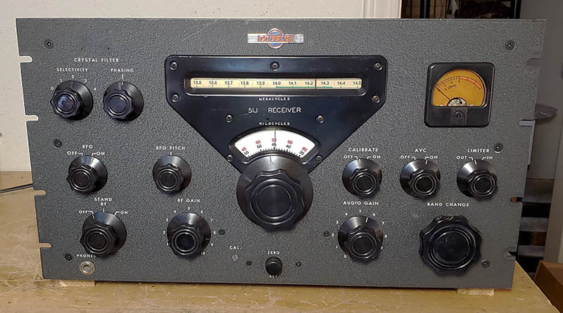
51J-4 - Collins Lab Receiver - SN:4723

 Some Servicing, Some Restoration and a Performance Evaluation

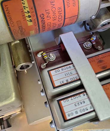
As the final version of the 51J Series one would expect the best performance to be from the 51J-4. The original market consisted of the commercial communications or laboratories users who had specific requirements with stability, dial accuracy and selectivity being at the forefront. Great audio wasn't a consideration since the bandwidth selectivity had to be kept narrow. The users today are all either hams, SWLs or collectors and this group definitely have different performance desires than the original purchasers had. 

51J-4 Stock Performance - For dial accuracy, stability and selectivity, it's hard to beat the 51J-4. Mechanical filters provide a superior selective ability to all but eliminate most QRM and the Crystal Filter can take care of heterodyne interference. Sensitivity is very good or at least competitive. Where the 51J-4 has problems is in its audio reproduction when listening to an AM signal. To say the receiver sounds awful on AM wouldn't be too much of an exaggeration for an audio purist (I'm not one but the stock J-4 audio still sounds pretty bad on AM, AM-BC or SW-BC.) I've owned two stock 51J-4 receivers and have recently found a R-388 with the 354A-1 mechanical filter conversion and all of them sounded (or sound) pretty much the same on AM. The AM signals would normally be tuned with the 6.0 kc mechanical filter selected. What is noticed is that on either side of the passband center the audio range is pretty good but at passband center the audio is "muffled." This is because the 6.0 kc filter is limiting the audio response to 3.0 kc at the highest. On either side of passband center you are tuning to one sideband or the other of the AM signal and the audio response can go up to 6kc or so and thus the audio highs sound better. This is normal AM reception for the 51J-4. In fact, Collins recommended that when tuning an AM signal to always use one sideband or the other depending on receiving conditions. Collins later also recommended reducing the RF Gain as needed to improve AM audio reproduction.

The drawing shown to the right is from the 51J-4 manual. Drawing (A) shows how in a typical "bell-curve" type of IF the AM signal has the carrier placed at the center of the passband and both upper and lower sideband information is detected and reproduced. If one tries to tune "off frequency" to recover more audio highs it can be seen that the carrier would be reduced as the signal is tuned further from the passband center and eventually distortion will develop. Drawing (B) shows the 6kc mechanical filter's "flat top" passband curve and how it allows tuning one sideband and the carrier without loss of carrier strength. This allows better reproduction of the sideband information plus the carrier because the ratio of carrier to audio modulation is preserved.

It all looks good on paper and certainly works fine with strong, constant-level AM signals. But, that's not how 90% of the AM signals are - except for local AM-BC stations (most strong local AM-BC stations sound pretty nice on the 6kc MF tuned to either the USB or the LSB. Too bad the programming is so dismal.) Typical SW-BC stations fade, sometimes producing phase distortion, ratios of carrier to modulation change and cause distortion, sometimes there are heterodynes from other SW-BC stations. With ham AM signals the same problems can exist in addition to QRM, carrier frequency drift and low modulation levels. In the real world, tuning the 51J-4 for an AM signal using the 6kc mechanical filter as described in the manual will work well sometimes, especially on the AM-BC band, but with SW-BC or ham AM signals, much of time distortion and restricted audio are very noticeable. If you get used to tuning AM signals in this one sideband plus carrier manner (and conditions allow for it) the audio will have more highs and will generally sound like decent communications-grade audio,...most of the time.


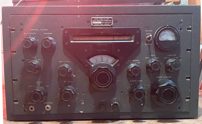
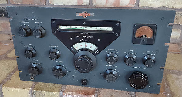
51J-4 SN:4723 from 1960

On SSB, drawing (C) shows how the sideband information should fit within the 3.1kc passband without any losses. The stock 51J-4 works quite well on SSB if it's operated as a typical early fifties receiver without a product detector. The same goes for CW reception. Of course, the 3.1 kc and the 1.4 kc filters can be used in those modes for greater selectivity. You can get away with using the 3.1 kc filter for an AM signal if QRM is particularly bad by selecting one sideband or the other depending on where the QRM is. Those who are 75A-4 users probably wonder why the Crystal Filter continued to be used when MFs are provided. The Crystal Filter is actually better for certain kinds of QRM, especially heterodynes or adjacent frequency SSB signals. The Crystal Filter Phasing can eliminate that kind of interference where the MFs can't.

As for the stock 51J-4, it was primarily for communications, not for aural-pleasure derived from band cruising using an ultra-wide bandwidth for high fidelity reproduction of idiomatic music transmitted by high-quality SW-BC stations (like China's Firedrake!) The basic 51J design was for data reception, not particularly for voice and certainly not for music reproduction. It's also important to remember that AM signals on the 51J-4 should be tuned to one sideband or the other. If you center the AM signal within the 6.0 kc MF passband then the audio will be restricted to 3kc and the audio will sound "muffled." The 51J-4 dial accuracy meant laboratories didn't have to have frequency meters anymore. Same with many of the military installations. Dial accuracy, frequency stability and excellent selectivity were what most users were interested in when purchasing a 51J-4. Great audio reproduction was not even considered since the passband had to be kept narrow for communications selectivity.

Having sold or traded off at different times formerly owned stock 51J-4 receivers, I swore I'd never buy another one,...ever! All it took to change my mind was seeing a light-gray panel laboratory version 51J-4. This receiver has a strikingly different appearance that stands out in the station landscape. And,...it's turned out to be a very interesting receiver since it has a Collins-installed "audio fix" for the 6kc MF position that allows decent AM reception.

Collins' Audio Fix - The R-388 receiver generally has much better AM audio reproduction than the 51J-4,...it's not high fidelity but it is an easily listenable, mellow-sounding reproduction. The only difference between the R-388 and the 51J-4 are the mechanical filters and the mechanical filter two-tube assembly that compensated for the insertion loss caused by the mechanical filter. All of the current ham modifications that might be found installed in 51J-4 receivers are for SSB reception rather than to improve SW-BC or ham AM reproduction. Since the R-388 has the exact same post-500kc-IF circuitry as the 51J-4 and sounds fine, the AM audio problems aren't with the AVC or the AM detector. There have been several published modifications to replace various types of mechanical filters with RC coupler circuits. Mostly this was either to replace a missing MF or a defective MF. Also, many of the mods wanted a wider passband than the available MFs could provide.

An interesting discovery was made while I was examining the light-gray panel 51J-4 sn: 4723. The receiver is almost certainly a Collins Lab or Test Receiver. It has several indicators but the two most compelling are the Collins Product Support sticker on the back chassis and the engraved Collins asset number on the front panel. One thing very apparent during inspection of the receiver was that Collins had removed the 6kc mechanical filter and replaced it with a plug-in RC coupler.

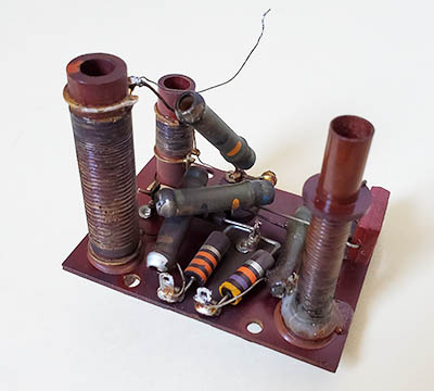
The coupler consists of a 4.7k input load resistor, a 47pf silver mica capacitor (the red body types Collins loved to use) and a 470K output load resistor. The components are vintage, the solder joints have age-patina and the workmanship is first-class with a garolite insulating base and proper pins for "plug-in" installation. Interestingly, on VE7CA's website, he has a section on 51J-4 receivers where he shows the exact same type of RC coupler that he found installed in his light-gray panel 51J-4. VE7CA also believes it to be a Collins-installed RC coupler. Photo left shows the RC coupler VE7CA found in his 51J-4. The photo is from VE7CA's website but is edited to show just the RC coupler. For VE7CA's write-up on his 51J-4 experiences go to www.ve7ca.net and click on "51J-4 PTO Rebuild."

As to the RC coupler operation, when selecting 6kc the actual bandwidth seems to be about 12kc or about 6kc out on each side until the signal becomes inaudible. However, the standard IF bandwidth that was determined by the addition of the 3pf capacitors on each IF transformer (installed in the 51J-4 only, R-388 used 2pf) and is about 8kc at -6db down. So, rather than the steep-skirts and flat tops of a MF passband, the passband curve is more like a typical non-Collins receiver. It's not as narrow as the R-388 (6kc at -6db) so there are more audio frequency "highs" present. The audio sounds pretty good and it's a noticeable improvement when using the 51J-4 listening to an AM signal with 6kc selected (which is now 8kc to 12kc.) Can it be that simple? Apparently, it can.   NOTE: May 2023 - I've been using this J-4 "on the air" several times in the AM mode using the RC coupler position. The AM reproduction sounds natural and communications grade. It really does make a significant improvement in the J-4 AM reproduction for communications.


Is that Collins' 51J-4 Audio Fix?
Apparently many 51J-4 users find the 6kc mechanical filter a problem for AM reception. There is another adjustable example shown on www.navy-radio.com

Modification Caveat - I wouldn't normally advocate this RC coupler as a "ham mod" except this seems to be a Collins "fix" and it does a good job in a very simple, "no holes drilled" manner. And, most importantly, it can easily be unplugged and the 6kc MF reinstalled, if desired. Well, I don't have that option but I already know how the J4 sounds with a 6kc MF! UPDATE: Now, I have a R-388 with the 354A-1 installation, so I can compare the 6kc MF reception on that receiver with the RC coupler in this receiver and the RC coupler improvement is very obvious. I can say this Collins "fix" gives the user a noticeable improvement in the quality of audio for AM signals. But, although the audio highs are improved there's still that 200hz roll-off in the bass, so don't expect miracles, but the AM audio has better intelligibility and that's a big help. Besides, there's still the 3.1kc MF for good SSB performance given that there's still the stock AM envelope detector and BFO injection level. Additionally, the 3.1kc MF can be used on AM by just tuning to one sideband or the other to avoid severe QRM. NOTE: I do most listening with the 3.1kc MF selected and only switch to the RC coupler if the AM signal is relatively strong and has good modulation levels. With the 800hz MF, a very narrow CW bandwidth is available (also works fine for 170hz shift RTTY.) Underneath, the receiver still appears totally stock (except for the new AC power cable installation with super-long wire lengths - I did a correct reinstallation of the AC power cable using the correct-type vintage strain relief and much shorter wire runs.) I have to say that sn:4723 has proven to be a very interesting 51J-4. I'm glad I didn't adhere to my stance of "I'll never buy another one."

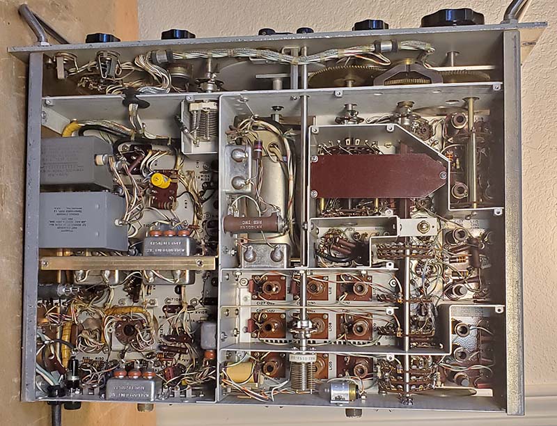
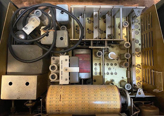
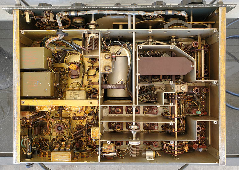
51J-4 sn:4723 showing the top chassis and underneath.

Servicing SN: 4723 - Jan 5, 2023 - This 51J-4 did function but it was obvious that it hadn't been thoroughly checked out in a very long time and that the sensitivity and gain were down quite a bit. The seller had indicated that he had tested the receiver before listing it and it picked up WWV at 5, 10, 15 and 20mc. So, since it had been very recently operated, I didn't really need to do a "pre-power-up" test. I could just go right to seeing how well the receiver worked. When operating, I could pick up many signals but the receiver didn't seem very sensitive, the CL meter wasn't moving and the receiver took a very, very, very long time to "warm-up."

Usually, a long warm-up time indicates a few to many weak tubes so the first thing to do was to test all of the tubes. All of the tubes tested very good BUT in the Mechanical Filter assembly one 6BA6 position actually had a 12BA6 installed. No wonder it took a long time to warm up. I momentarily thought the 12BA6 in the MF IF amplifier might have been some type of mod. Something like "install a low gain tube for reduced distortion" but I think it's more likely that was the closest "BA6" tube a former owner could find. With all good condition tubes, SN:4723 had much better sensitivity. I set the zero on the CL meter and could just get about a 10db increase by tuning in WWV, so sensitivity is not up to spec, yet. But, the Calibrator signal will drive the CL meter up to +60db so the problem might be the limitations of using a Pixel Loop antenna indoors (heavy wet snow took down my 135' Inv-vee Tuned antenna.) There wasn't any change in the audio quality, so I'm pretty sure the 12BA6 was installed because that was the only "BA6" easily available (out of the junk box?)   >>>

>>>   I did a quick end-point check on the PTO and got 4.5kc change over 1.0mc span. That's not too bad considering most 70E-15 PTOs have EPEs that are >6kc and they're so far out they aren't even adjustable. 4.5kc should be able to be adjusted down to <1kc EPE using the compensation adjustment on the front of the PTO (unless it has already been adjusted and 4.5kc EPE is a good as it gets.) 

There was a lot of "crackling" in the audio output that seemed to originate in the MF assembly caused by a dirty tube socket (the one that had the 12BA6 installed.) Cleaned the tube socket with DeOxit to correct the problem.

The MF selector switch shaft slips a little and it must have been a long-term problem because the bristol screw that tightens the bell-crank lever to shaft clamp was virtually stripped of its splines so the clamp couldn't be fully tightened. Easy to replace, so I installed a good condition spline-head screw but, when tightened, the apparent "slipping" still occurred. The problem was in the bell-crank lever on the MF assembly switch shaft was slipping on that shaft because the set-screws weren't tight. After tightening the set screws the MF selector switch level worked like it should.

I'll run SN:4723 for a few more days to get some hours on the tubes before I do an alignment.

The ink-stamped number on the back of the chassis is "2" - that's all, just a single digit. Of course, the Collins tag has 4723 for the serial number. Navy-radio.com has a listing of several 51J-4 numbers and it looks like with the early production, serial numbers and the rear chassis ink-stamped numbers usually matched. By about SN:1000, this is no longer the case and the ink-stamped numbers become very low numbers while the SNs are four digit. There are a couple of exceptions, one as high as a SN in the 6000 block, but on most of the later 51J-4 receivers the SN and the ink-stamp number don't match.

Detailing - Jan 8, 2023 - Although this 51J-4 didn't really look it, it was pretty dirty. I was amazed at how much gunk came off with Glass Plus. Someone in the past had polished the panel with something that left a white power residue. It couldn't have been too abrasive since the silk-screened nomenclature looks fine. Also, the index lines on the knobs were crudely redone as were the index marks and nomenclature on the bezel. I dismounted the knobs, cleaned the panel and then individually cleaned each knob. I had to carefully use a razor blade to shave off the excess white paint on the index lines before reinstalling. I removed the bezel and cleaned it with Glass Plus and then polished it lightly with Wenol's. The two glass windows were very dirty but cleaned easily with Glass Plus. The bezel and windows were then reinstalled. I had to clean and darken the bezel screws as they had lightened somewhat. I use "real paint" pens with black paint to darken the screw heads. Once the screw head has been painted and before the paint dries, blot the paint with a dry cotton cloth to "dull down" the paint gloss. The screw heads look original after that. The panel is in very good shape. The paint has a semi-gloss sheen to it when clean. Jan 12, 2023 - AC Power Cable - I really didn't like the way the AC power cable had been installed. It might have been part of some Collins rework but I doubt it. The power cable was just stuck through the chassis hole (not even a grommet) and a plastic wrap-around clamp was installed on the inside (and that was after a new hole was drilled for the 6-32 mounting screw for the clamp.) The proper and original method of installation required using a molded black plastic strain-relief that will clamp the AC cable and mount into the chassis "double-D" hole. I looked at new strain-reliefs at the hardware store and they are pretty cheap looking. Back home, I checked all of the parts bins and managed to find a vintage strain-relief that was the correct size. These are difficult to install unless you have the correct tool. I haven't seen one of the proper strain-relief installation tools in over 30 years. But, I used 16 gauge wire wrapped and twisted to compress the strain-relief to get it into the chassis hole. Then the wire was cut after which small channel-locks can achieve the right angle to compress and push the strain-relief into position with the cable inside. I had to cut and then remove the original connections by unsoldering and also had to clean the joints with Solder Wick for new soldering. I then trimmed and routed the three AC wires correctly, stripped and tinned, then mounted and soldered the AC connections to finish the installation,...correctly. The photo of the underside of SN:4723 above shows the new AC power cable installation.

Missing Screws - A pet-peeve, I guess. I bought all new 4-40 x .375" pan head, Phillips, SS machine screws along with flat washers and locking washers to correctly mount the bottom cover with all the same type of screws (19 screws are required for the bottom cover.) Bought three 6-32 wing-nuts and flat washers for securing the top cover correctly.

IF Alignment with Mechanical Filters - The manual indicates the IF adjustments should be performed with the 3.1kc MF selected. Monitor the Diode Load output with an analog VTVM and keep the signal generator output at a level that produces about -3.0vdc on the Diode Load. Connect the signal generator through a .01uf capacitor to the grid of the last Mixer V-107. The manual indicates that a RC load consisting of a .01uf cap in series with a 4.7K resistor needs to be connected to the IF transformers as they are adjusted (a simple shunt-LP filter that keeps the IF from mixing with the crystal oscillator and PTO since you have the bottom cover shield removed.) Peak all of the IF transformers top and bottom while moving the shunt load as directed in the procedure. There's also the adjustment on the mechanical filter assembly. Recheck to be sure that all adjustments are at peak at the correct input frequency. Disconnect the signal generator and the VTVM.

Test the IF alignment by tuning through a broad AM signal with the 6.0kc MC filter selected. Carefully listen to the signal as you tune from one end to the other. You should hear the AVC quickly attack at the low end of the passband, then the signal will quickly clear up and as you tune through about 2 to 3kc or so, the signal should stay constant and clean with fairly high audio frequency response. You will hear the AM signal narrow in audio bandwidth at the center of the 6.0kc filter but the signal level should remain constant with no distortion although with reduced higher frequency audio response. As you tune out of the high end of the passband, the audio frequency highs will increase for 2 to 3kc and then the AVC will react to the noise as the signal is quickly reduced by the steep slope of the mechanical filter.

This should be repeated for the 3.1kc filter and the 1.4kc filter also.

IF Gain Adjustment - One other thing though, if you have a later version 51J-4, it should be equipped with an IF Gain adjustment. This should be set last after the completed IF/RF alignment. The proper IF Gain setting was first accomplished at the factory, but that was over 50 years ago! Different tubes and component aging requires that the setting should at least be checked. The Collins procedure requires injecting 3uv into the antenna input at 2.1mc and then setting the IF gain pot for 270mv output on the IF OUT coax connector on the rear chassis. At the time this procedure was written measuring a RF level was commonly accomplished using a VTVM with RF probe and measuring the RMS voltage value specified. The manual assumes the alignment tech knows how to measure RF levels since nothing is mentioned in the procedure.

NOTE: This IF Alignment section is general information on how I align 51J-4 receiver fixed IF sections, not specifically for SN:4723.

Unneeded Alignment of SN:4723 - Jan 20, 2023 - After using SN:4723 for a few weeks, I felt the receiver was already pretty close in alignment. The fixed-IF was especially nicely adjusted because the Crystal Filter seemed to function just as it should. The date in 2013 that was written on a paper stick-on label stuck on the multi-section plug-in filter capacitor was probably when the receiver was last serviced and probably aligned at that time. There were a couple of checks that I performed however. First, I pulled all of the crystals in the Crystal Oscillator to check the sockets and pins for any corrosion and none was found. I then measured the Crystal Oscillator output and adjusted all of the trimmers for just under 2 volts. All of the trimmers had been set a bit lower in voltage but that was probably okay. Next, I aligned the Variable IF. Again, nothing was very far off from being in alignment and only needed slight peaking. Then the RF section was adjusted. This was only slightly off on a few adjustments. Last was the .5 to 1.5mc band and, again, nothing too far off, just a slight peaking of the adjustments. There weren't any problems with stuck trimmers or slugs, everything adjusted easily. A quick test using a ten foot wire "test" antenna on the AM-BC band and KOH 780kc pushed the CL meter to +80db. On the Pixel Loop, WWV 15mc pushed the CL meter to +40db (even WWV 20mc pushed the CL meter to +40db!) So, I've done alignments like this before. It's where you turn an adjustment only to put the adjustment back where it was. There were one or two slight adjustments needed but most were just "move and return" types.

UPDATE: Feb 9, 2023 - Finally, I've been able to repair the devastating antenna damage sustained during the Dec 31, 2022 mammoth, wet-heavy snow storm that took down both of my large wire antennas. My two half-waves in-phase antenna (collinear array on 75M) is now rebuilt and functioning correctly with the feedline now running 108 feet to the upstairs ham shack (it had been a "shop" antenna only, with 77ft of feedline.) The antenna itself is now a center-fed tuned 234ft dipole (it had been 270ft) that operates as a collinear array on 75M (~1.9db gain) but can be "tuned to operate" on almost any frequency above 3.8mc.

All testing and listening for the past month has been with a Pixel Loop or with a 84ft sloper antenna (with tuner.) The 51J-4, now operating with the two half-waves in-phase as the antenna, is like a "new" receiver. Strong signals on 80M, 40M and 20M are always present now. WWV on any frequency will push the CL meter to +50db or more. Coastal beacons in China are strong (XSG or XSQ on ~16.85-.98mc or on 12mc later in the afternoon) and even the coastal beacon SVO in Athens, Greece is an easy copy on 8.4mc in the late-afternoon as is TAH in Istanbul, Turkey. Utilities stations, like Trenton Military, are easy copy on 15.035mc USB with aviation weather out of Canada (Trenton, Ontario is near Toronto.) Some of the SW-BC stations are incredibly strong, especially those out of China in the late-afternoon. Though Radio Havana puts in a very a strong signal here in Western Nevada, I think the broadcast-quality audio of the Chinese shortwave stations is superior to RH. These powerful SW stations sound pretty nice with the 12kc RC coupler switched in (even though it's communications audio.)

Strong signals make a substantial difference in the audio quality of the 51J-4. Weak signals are going to sound like "weak signals" and that's true for just about any receiver. A really good antenna does help provide more substantial signal levels with better audio reproduction results from the 51J-4. With antennas that are a "compromise," over-all performance will suffer somewhat. So, I like how this 51J-4 operates now with a full-size antenna and I do plan to incorporate it into a vintage station running with one of the Collins 32V transmitters.

UPDATE: Feb 19, 2023 - J-4 SN:4723 "on the air" with the 32V-3 transmitter running with the collinear-array antenna on 75M. No problems in Q5 copy of all stations. Used RC coupler position for 12kc bandwidth. Nice sounding!

UPDATE: Apr 1, 2023 - I've installed SN:4723 into a recently acquired, genuine 51J-4 Collins Cabinet. The loudspeaker is a 270G-3 I've had since 1970 (which is why it still has all of its original cream-color flocking.) The 51J-4 is now paired up with the W6MIT Homebrew "1625 Rig" which uses a T-368 Exciter to drive a pair of parallel 1625 tubes as the PA and another pair of push-pull 1625 tubes as the modulators. The 1625 Rig can produce 75 watts of AM carrier output power or 100 watts output in the CW mode. From this operating position the antenna used is the 234' Collinear Array.

UPDATE: Nov 25, 2024 - For the past few months it seemed that the sensitivity was down quite a bit on SN: 4723. If I connected an antenna directly, that is, not through the 1625 Rig and its antenna relay, the signal response seemed normal. If I connected another receiver through the 1625 Rig, it seemed to function normally. I finally decided to check the 51J-4 on the workbench and determine if there was a problem. I used a HP606B RF signal generator to input a known level of signal. The output attenuator on the HP606 is calibrated to a 50Z load so it's a close match to the 51J-4. I tested 7mc and had 30db on the CL meter but switching to 8mc, I then had 40db on the CL meter. I saw a gradual increase in the CL meter reading as I switched from 6mc to 5mc and then to 4mc. 4mc read 40db on the CL meter. It seemed something was causing a 10db loss on 7mc. The only circuits specific to 7mc would be the crystal oscillator 10.000mc crystal or maybe the C trimmer on the 4-7mc band was off. I realigned the 4-7mc band and got a 2db increase. I thoroughly cleaned the crystal oscillator switches with DeOxit. I cleaned the band switches with DeOxit. I removed all of the ten crystals and cleaned their pins with DeOxit and reinstalled them. This seemed to clear up the problem. All of the bands seemed to have the same noise response now. I connected up a shielded magnetic loop antenna and tuned AM-BC where KKOH showed 55db on the CL meter. I tuned 10mc WWV showing 45db, 15mc WWV showing 40db. 40M ham band seemed normal. 20M ham band seemed normal. I'm not sure what was causing the decrease in 7mc sensitivity but it probably was the crystal oscillator switches or the crystal sockets or maybe the band switch. I didn't clean any of these when I first was servicing this 51J-4 first time around. Maybe I should have been more diligent in my electronic cleaning. Anyway, it seems to be working normally now. When connected to the Collinear Array antenna going through the 1625 Rig, 15mc WWV pushed the CL meter up to 60db. 20mc WWV read 50db on the CL meter. I should have done this cleaning the first time around.
 

Pseudo R-388A* - 1951 R-388/URR with 354A-1 Mechanical Filter Kit Installed

R-388/URR,  Order 3096-PHILA-51,  Mil SN:33,  Collins SN:5282

Lots of Repairs, Lots of Missing Parts, Some Restoration Required

When ordered from Collins, the 354A-1 Mechanical Filter Kit came with all of the parts and components necessary for the installation. Included with the kit was a 28 page manual with its 78-step list of instructions with appropriate "check-off" boxes after each step. The 354A-1 installation wasn't for beginners. It required a person with considerable experience, both mechanical and electronic, meaning that the conversion work would have best been performed by a professional electronics technician,...or,...maybe not. This R-388 receiver and the 354A-1 installation certainly shows what can happen when "functionality" is the only requirement. This write-up is concerned with correcting a litany of electro-mechanical problems involving the installation of the 354A-1 kit along with years of incompetent maintenance that has left this receiver almost a derelict.

* Sometimes these R-388s with the 354A-1 conversion are referred to informally as a "R-388A." I don't think the Federal Procurement Book listing of the "R-388A" was referring to a "converted receiver" since the book price was $1200. But, since no example of a R-388A has ever been found, these conversions are about as close as one can get. So, I guess they can "unofficially" be referred to as "R-388A" receivers.

Discovery - Mar 10, 2023 - I came across 1951 R-388 SN:33 while I was researching 70E-15 PTO serial numbers as part of this "51J Series" write-up. The receiver was listed on eBay as a "R-388" but when looking at the photographs to see if the seller had included a chassis photo that showed the PTO serial number, I was surprised to see the 354A-1 Mechanical Filter Kit installed. Then I noticed the serial number of the PTO was 11277 with no "M" prefix that indicated to me immediately that this was a replacement PTO. The serial number for the PTO was from the 1960s. I was intrigued and studied the condition of the receiver as much as could be determined from the photographs. I noticed that the AUDIO terminal strip was a replacement. I also noticed some mismatched screws. The most glaring absence were the two grab handles and the missing top cover. The megacycle dial drum had a few fairly severe scratches. In all, the receiver looked in decent condition and worth taking a chance on since it was the only time I'd seen a R-388 to 51J-4 conversion. I asked for and received a 25% discount and the receiver was purchased, packed, shipped and delivered within a few weeks.

The photo to the right is how the receiver was shown on eBay in "as found" condition. It actually was much dirtier than it appears in the photo. The chassis was covered with greasy grime and the front panel had streaking where rusty water had dripped down the panel. The red flare is from a window reflection. This is actually a very poor quality photo compared to the chassis photo from the same auction, shown below. At least it does show that all of the knobs were present and in good condition, the meter was correct, the bezel was undamaged and the condition of the front panel was decent.

Inspection - Mar 28, 2023 - Here's what was noticed in the visual inspection after the receiver was unpacked.

1. No top cover (known in advance - kia.)
2. L-110 broken at the base, wire end of coil broken and the L-110 slug broken into two pieces and separated from the adjuster screw.
3. Crystal Filter control shafts not aligned with the front panel very well. Phasing control adjustment really "rough-feeling."
4. Drum dial cable isn't the original plastic covered metal cable but is regular "dial cord." It does work okay. Dial Drum is scratched in several places that align with the screws on the 354A-1 MF kit.
5. Bottom cover isn't MFP'd - not a repro, possibly from a J-4. Bottom cover was held in place with the typical "hamster one screw" - and it was a "self-tapping" sheet metal screw! Correct mounting requires the use of nineteen 4-40x1/2" Phillips screws with external tooth lock washers! (I ended up having to "chase" the threads on several of the 4-40 tapped holes used for mounting the bottom cover.)
6. Three of the tub capacitors (two electrolytics and one dual bypass) have been replaced with same type as the originals. They aren't MFP'd so they must be replacements. Also two ceramic disks and one resistor that are obvious replacements. Mostly original components. No mods to detector, BFO or AVC circuits.
7. The 3.1kc MF has a different exterior finish - kia. Later replacement? The 1.4kc and the 6.0kc MFs match with gray paint finish and metalized labels.
8. Removed the data plate and "5282" was ink-stamped underneath indicating this was the original front panel for this chassis.
9. Aluminum scrap metal piece used for filter cap hold-down - kia. Undoubtedly a hamster fix.
10. AUDIO terminal block is a replacement type, not the original style or size - kia.
11. Grab handles missing - kia. Also, a few mismatched screws on front panel and two screws missing from the right side-panel to chassis and many mismatched or missing screws, washers and nuts everywhere.
12. The 70E-15 PTO SN is 11277 from the early-60s making it an obvious replacement - kia. End-point measurement should be interesting (it was.)
13. The bushing that should mount in the 354A-1 MF Kit panel extension to provide support for the BFO/MF switch shafts is missing. Maybe it was never installed. The shaft coupler to the BFO is solid metal (homemade?) and the manual explicitly warns that only the supplied insulated coupler should be used or noisy operation of the BFO will result (it did.)
14. The rear support and thrust bearing for the ZERO ADJ. control shaft is entirely missing. Plated round-head machine screws are filling the mounting holes.

Overall, the receiver is in typical "as-found" condition and, although this inspection was mainly for mechanical problems, it appears that this receiver can be repaired, refurbished and made operational. More details on some of the problems follows,...

L-110 Problem - This is the tuned input coil for the Band One and First Mixer. This coil and slug are only used for the AM-BC band, Band One on the receiver. Luckily, L-110 never changed from the 51J-1 up to the 51J-4, so I can extract the entire coil assembly from my "parts set" 51J-2 for the repair. It may not be necessary to remove the entire coil assembly which has some circuit wiring involved (also, the early version had slightly different dissipation resistors.) If I could successfully epoxy L-110 back in place with it aligned mechanically for the slug, then all I would need to do is to use the slug from the 51J-2.

Dial Cord - This is actually called "flexible wire rope - extra small diameter - nylon coated" and it's available from McMaster-Carr. The original spec was for .015" diameter but, per the manual, .032" diameter was optional for repairs. McMaster has .024"dia and .032"dia. McMaster PN 8930T51 for .024"dia and PN 8930T53 for .032"dia. Original installation cables had brass crimp fittings but repair instructions indicate "knotting" was acceptable. I can salvage the cable from my "parts set" 51J-2. Although the Army TM R-388 manual states "nylon covered string" for the drum drive repair, all R-388s I've examined have nylon covered flexible wire rope for both the dial pointer drive and the dial drum drive. The AN/URR-23A Navy manual and the 51J-4 manuals call it "nylon covered cord." 

Non-original AUDIO Terminal block - I should be able to salvage a correct style replacement from the "parts set" 51J-2.

Crystal Filter Controls - There is an adjustment guide plate mounted to the backside of the front panel for adjusting the position and angle of the control shafts as they exit the front panel.

Filter Capacitor Hold-down - The R-388 should have a 5V4G rectifier tube which then uses the "flat" hold-down. Many times the 5V4G was replaced with a shorter 5V4GA tube and the "flat" hold-down couldn't secure the 5V4GA. Receivers like the 51J-4 used a "stepped" hold-down specifically for the 5V4GA tube. Sometimes, when a 5V4GA was installed in a R-388, the depot would cut the "flat" hold-down so that it only worked to secure the filter capacitor. I had a spare "half a hold-down" with the grommet still present. Since this was a depot-modified piece it was installed using a proper wing-nut.

Data Plate - One is never sure anymore whether a data plate is original to the receiver or not. The Collins production serial number of 5282 along with the MFP date of Oct 1952 seems late for a 1951 contract receiver with a Mil SN of 33. The Order date is when the contract was issued and it might take a while for the contract to actually be filled. Also, other order quantities might be put on the same contract at a later date. However, usually the Mil SNs were consecutive within the contract which should indicate that this receiver was among the earliest supplied on the contract. As said, one never knows anymore whether any data plate is original or not. However, a check on navy-radio.com to look at the lists of R-388 contracts and receiver data, I noticed that, when the information was provided, all of the 1951 contract receivers seem to have been MFP'd in Oct 1952 and many of the Collins SNs are very close to 5282, so maybe the data plate is original.

Dial Drum Scratches - These scratches are pretty deep and removed some of the dial background color. These scratches align with the screws on the 354A-1 MF kit. The installation instructions give explicit directions to cover the dial drum with heavy paper or other protective material to prevent dial scratching during the kit installation,...but who reads the instructions? Touch-up shouldn't be too difficult. The remaining sections of the dial are in very good condition so a new overlay isn't really necessary.

ZERO fiducial adjustment control shaft bearing is Missing - Luckily, one of my "junk" R-388 front panels had this piece and the mounting screws and nuts and washers.

Grab Handles - I bought a set off of eBay for $25. Included the correct mounting screws and locking nuts.

Detailed Under-Chassis Inspection Nets Disappointing Results - Apr 5, 2023 - As much as I wanted this R-388 conversion to a 51J-4 to be a military depot reworking (and be about as close as one can get to a R-388A,) I'm convinced now that it's the work of either a really inexperienced ham or an indifferent and extremely lazy commercial electronics technician. For the latter, that would be someone working in electronics repair in some capacity with some experience but where the repaired or modified unit's functionability was the only requirement. I was sure this was an amateur super-hamster job until I discovered the "INSPECTION/O.K." ink-stamp on the rear chassis. Certainly a ham wouldn't be responsible for the ink-stamp and neither would the military nor Collins. It seems like something that a commercial outfit would do. A good example would be the electronics maintenance technicians at airports or especially at broadcast station maintenance facilities. These technicians were never known for neat repairs or complete reassembly because of their directive was to, "get it working as fast as possible!" Though I am surprised they took the time to inspect the rework and apply the ink-stamp.

At first glance, the workmanship looked exactly like a "hamster" that could afford all of the necessary Collins parts but didn't have the mechanical aptitude or the electronic experience to perform the 354A-1 installation correctly. Combining hamster ineptness with a crude soldering technique and "strong-arm" component removal/installation resulted in the "worse than typical amateur level" 354A-1 Kit conversion. The 354A-1 installation and other repair work seems to use lots of mismatched "junk box hardware" and the persistent use of screws and nuts installed without locking washers, or, even more common,...leaving the screws or other parts out altogether. Soldering was another important clue. It's difficult to rework any electronic device that has been MFP-coated. However, mil-depot technicians and other experienced professional electronics techs that are given the time and have been trained using the proper tools for cleaning the MFP'd joint, performing the rework, resoldering the joint and then recoating the joint with new MFP, will produce excellent quality workmanship. None of that happened. The MFP was burned-through with the soldering iron, the wire "ripped out" of the terminal, the joint not cleaned afterwards, the wire ends not reconditioned and, after the rework accomplished, the new solder joint wasn't recoated with MFP. Also, in examining the type of wire lead wraps, which should be a good clean full wrap of a properly tinned wire end, it was found that many of the joints weren't wrapped at all but were wires "pushed though a lug hole" and then soldered which is just one step above "tack soldered" joints.  So,..."hamster work?"    >>>


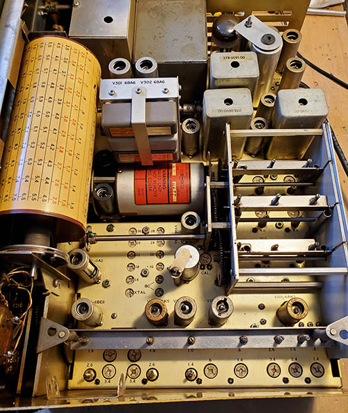
1951 R-388 SN:33 Chassis as received

The ink-stamp evidence
 

>>>  This receiver had all of the indications of an inexperienced, amateur-level type of work perpetrated by a ham that, while he could afford all of the Collins parts necessary for the conversion, just didn't have the capability to do the work properly. But, then there's that "INSPECTION/O.K." ink-stamp, shown in the photo to the left. "INSPECTION/O.K." is pretty easy to make-out. The next line is illegible except for "INSPECTION" (I can almost make out the "AL" in "FINAL.") The first line is probably for the inspector's initials and then the "DATE" line. The ink-stamp is the only evidence that might indicate some other type of culprit was involved in the conversion - someone other than a ham, that is. It looks like a professional ink-stamp for QA on the reworking of whatever item the stamp was applied to.

Some rhetorical questions,...   How would a ham have known that the 70E-15 "M" PTO should be replaced? What was the cost of a replacement PTO purchased from Collins? Where would the original tub capacitors have been found? Collins? Could the ham have afforded (at the time) a surplus R-388? Also, where did the 354A-1 come from? What was the cost if purchased from Collins? What about the genuine Collins 51J-4 cabinet? Expensive? On the other hand, why would a commercial user remove the grab handles? Why was a cabinet needed? Whether a "hamster" or whether a "commercial technician" was the perpetrator can't really be determined. In the case of this receiver, the one thing that's obvious is that the workmanship quality is dismal.  >>>

>>>  Since the receiver isn't a mil-depot conversion I won't feel too guilty in going through the receiver and correcting the quality issues with the goal of making the installation look (and function) more like a "professional rework job." Also, other quality issues, like the use of dial string for the dial drum cable or the missing or wrong types of screws and the litany of missing lock washers or the scratched dial drum, will be corrected. Where MFP should have been reapplied, I'll recoat using my mix of yellow-tinted lacquer that looks like MFP but doesn't have the fungicide in the mix. I might feel a little guilty going in and disturbing such a perfect example of incompetent electro-mechanical reworking technique, that while the installation does "sort of work" (which may have been all that was desired,...or required) shows the lack of professional technique that we all hate to see.

General Complaints - Another common problem found in equipment that was worked on by some commercial techs working in the types of facilities where the directive is to perform repair work as quickly as possible with functionality being the only requirement, are "shortcuts." These are little time-saving actions, both for the present and for the future, that are found throughout the device. Since any rework takes time, any hindrances that would require extra time to deal with must be removed. That means during reassembly all lock washers are discarded. If dual set screws are found, one set screw is removed and discarded. If a shield can be eliminated and discarded, it will be. If the number of screws can be reduced, those screws deemed "superfluous" will be removed and discarded. Chassis covers are generally discarded using the excuse "they hold in the heat and heat causes more failures and that requires more work." Although these missing bits of hardware are also commonly found (to a certain extent) on self-maintained ham gear, when restoring any apparatus that was in a commercial broadcast environment or a commercial monitoring set-up where the business had their own electronics technicians you better have a "parts set" available because you'll find out just how many parts can be missing from a device and it will still function,...sort of.

70E-15 PTO SN:11277 End-point Error Test - I performed a "quick test" of the receiver to determine if it could be powered-up. The quick test is to pull the 5V4 rectifier tube. That way no B+ will be created and only the filaments are on. Also, the HVAC can be tested at the rectifier socket. This quick test assures that the power transformer is okay and all of the low voltage circuits are operational. All tubes tested okay - not great but okay. I reformed the filter capacitor and afterwards it measured 48uf and 42uf with the spec'd capacitance being 35uf, so it was okay. I installed a plug on the less-than-perfect AC cable. I connected a speaker and 10ft test antenna. I reinstalled the 5V4 tube and then brought the R-388 up using a Variac, just in case. No problems and the receiver started to reluctantly pull-in WWV on 10mc. Went to 15mc and WWV was present. I checked the Calibration Oscillator and it must have been off frequency by at least 3kc. Luckily, the CAL trimmers brought the oscillator beating with WWV, so that was close enough. Using the Calibration Oscillator, I tuned through from 14.5mc to 15.5mc noting each 100kc increment. I was expecting very little End-point Error since this was a much later PTO but the EPE measured 7.5kc! This was totally unexpected.   >>> >>>  Though unexpected this EPE test does confirm one thing about 70E-15 PTOs. The excessive EPE wasn't ever corrected in the 70E-15 PTO because the problem is not necessarily with the ferrite core but in how the receiver was used. This receiver does show signs of excessive use with lots of discoloration of the MPF everywhere (MFP darkens as it ages under a heated environment.) There are wear patterns by the MF bandwidth switch indicating that a lot of the use was post-conversion. This receiver may have been in some type of commercial use where 24/7 operation occurred and the excessive heat build-up affected the ferrite core just like most of the military "M" PTOs were affected. From other clues, I suspect this receiver was converted to a 51J-4 for use at an airport or airport support where the receiver(s) operated 24/7. It could also have been a 24/7 broadcast or frequency monitor of some type.

At 7.5kc EPE, it might be possible to adjust out the error but that's probably just a wishful reverie.

Rework Details

Replacing the Dial Drum Cable - This was white fabric dial cord with a fiberglass core which is pretty strong stuff but the original cable was a .015" diameter flexible wire rope with a nylon covering. As mentioned above, replacement flexible wire rope can be purchased from McMaster-Carr. I used original flexible wire rope harvested from a "parts set" 51J-2 receiver. The installation instructions are the same in all manuals for all 51J receivers.

BFO and MF Switch Shaft Bushing - This piece was missing. It's a standard .250" shaft bushing that must mount with a panel thickness of less than .125 inches. The MF Kit panel is .060" aluminum with an over-size mounting hole to allow centering the bushing. Because of the over-size hole, two washers or adapter plates have to be used. Originally the assembly used a square shaped spring washer but the washers or adapters would also work fine. Found a .250" bushing that would work and made the square adapter plate out of .060" aluminum.

BFO Coupler - This was a more difficult piece to find. As mentioned, the receiver has a homemade solid brass coupler. The 354A-1 instructions are explicit that an insulated coupler has to be used to avoid noisy operation of the BFO. Unfortunately, one side of the coupler has to interface with the 3/16" BFO coaxial shaft from the front panel and the other side of the coupler has to interface with the 1/4" shaft from the BFO LC assembly. I found an insulated coupler that was for a 1/4" shaft on one side and for an 1/8" shaft on the other. I just enlarged the 1/8" hole to 3/16" (used successively larger drill bits to keep the hole centered.)

Broken AVC Switch - This is a fairly common problem. Only half of the switch is actually used and normally the half that would break off was the unused section. Since it didn't affect operation, a lot of the broken switches were left in place. However, these fiber board switches are extremely fragile and have become even more fragile after three-quarters of a century of existence in some types of environments. This AVC switch broke when I was cleaning it and that was when gently cleaning with DeOxit and a small paint brush. At least I had the broken piece.   It's very easy, if you have the front panel dismounted, to use epoxy to repair the broken switch. As mentioned, only half of the switch is used so it's not ultra-critical in its operation but it should have good alignment so the switch operates easily. I applied the epoxy with a wooden toothpick and was careful to not allow the epoxy to "run" into the contacts. I used just enough to hold to broken piece securely. The reason only half of the switch is used was so Collins could use the same type of switch for four different switch applications, AVC, BFO, LIMITER and CALIBRATE.

The Original 51J-4 Cabinet - I had a much better candidate for inhabiting this pretty nice Collins cabinet. First, this 51J-4 cabinet needed a little mechanical "tweaking" to get it straight. I used a pipe clamp to slowly straighten the cabinet so it was again square. Then I had to use some bodywork to fix the left side of the cabinet where it had been pushed in. This allowed the front panel to set in the recessed area correctly. This was followed by a thorough cleaning and paint touch-up. So, what was the candidate? I've installed the light-gray panel 51J-4 in this cabinet.

Cleaning Chassis and Front Panel - The chassis top was covered with greasy grime. I used WD-40 to cut the grease and cleaned the WD-40 residue with Glass Plus. R-388 chassis will usually clean-up quite well because of the MFP coating protects the metal from corrosion (most of the time.) I used acid brushes, small paint brushes and Q-tips along with paper towel strips for cleaning the chassis.

The front panel had to be dismounted and completely stripped of parts for a thorough cleaning using Glass Plus and a variety of brushes. Most of the time with wrinkle finish I can use a brass bristle brush in a gentle motion to remove thick grime in the wrinkle convolutions. Otherwise, acid brushes and small paint brushes are used. I was very careful around the "1KC, 3KC and 6KC" nomenclature since that wasn't original silk-screening and consequently was extremely faded. While cleaning didn't damage it, it didn't improve it either,...it's still pretty faded. Once the front panel was clean, I touched up most of the nicks and scratches using Artist's Acrylic mixed to match St. James Gray. Then the front panel was given a rub down using "3 in 1" machine oil to bring out the luster. Excess was wiped off and the following day another rub down with oil and wipe off the excess. This treatment lasts for several years.

KC Dial Oddity - I thought this KC dial looked slightly different from the front. The white background seemed to be very slightly "streaked" as if it was brush-painted on. Also, the numerals were slightly thinner and somewhat pale looking. Once I had the KC dial dismounted and could look at the backside I found that it was painted! This KC dial is different than the normal R-388 dials in that the numbers and scale index are engraved into the plastic on the backside. Then the numbers and scale index were filled with the appropriate red or black paint and then the entire back painted with a semi-transparent thin white paint. All R-388 KC dials I've seen were plastic laminations with no engraving. So, where did this KC dial come from? Sometimes the military had their own methods of reproducing parts when OEM parts weren't available. I doubt this is homebrew, it's too well made and way beyond the capabilities of the technicians that worked on this receiver after its military career. As far as the hub and the mounting of the plastic to the hub, it all looks "factory." Is it possible that when the 354A-1 kit and the new 70E-15 were obtained from Collins that this dial was also an "after production" replacement that Collins provided?

Front Panel Remount - The grab handles must be mounted first since the flat head mounting screws are covered by the side panel flanges. After that, I used two 16 gauge wires the were attached to each top corner of the front panel and to the top corners of each side panel. This allows the front panel to be supported while laying "face down" in front of the receiver. This allows easy installation of all of the controls, switches and harness clamps. There are control internal tooth locking washers that must be installed on each control. The AF Gain, RF Gain and the OFF-STAND BY- ON switch all have their lock washers mounted so they are on the outside of the front panel. The BFO, CALIBRATE, AVC and LIMITER switches all have their lock washers mounted on the inside of the front panel. Care must be taken when mounting these four switches that they are exactly vertically aligned. This is because these switches have shaft flats that align with the set screws of the knobs so that the index line will be in the proper position to indicate the correct function of the switch. I mounted the carrier level meter while the panel was down (the meter was removed for cleaning.) The panel had to be raised up to be able to mount the AVC and LIMITER switches (I just shortened the support wires.) Once all the controls were mounted then the panel was guided so the CAL. shaft and the ANT TRIM shaft were in their panel holes and then as the panel was close to being in position, the CRYSTAL FILTER controls were guided though their holes. Then the support wires were removed. Once it's assured that no wires were being pinched by the panel, I installed the screws. Once the panel was mounted, then the screws, lock washers and nuts that retain the two harness clamps could be installed. All that remained was final "snugging up" of the control mounting nuts, cleaning and installing the knobs, aligning the KC dial and the MC drum dial, reconnecting the CL meter and mounting the METER switch.

AUDIO Terminal Block Replacement - I found a NOS terminal block that was identical to the original but it looked so new that it was obvious that it was a replacement. I removed the AUDIO terminal block from the 51J-2 "parts set." It was in good condition and showed the patina of age that made its installation look original. One would think that there wouldn't be any problem with such an easy task but,...the non-original type of terminal block had mounting holes that were spaced slightly further apart than the original. In typical hamster (or incompetent tech) fashion, instead of modifying the part, another hole was drilled in the chassis apron to mount this incorrect part,...unbelievable. I filled the non-original hole with epoxy and touched it up to match the MFP color of the chassis. The installation of the correct type of terminal block was easy. Oh, and of course, the incorrect part had been mounted without lock washers so I had to install the correct #4 external tooth locking washers when mounting the original type part.

SO-239 Replacements - These two UHF coaxial receptacles are for the IF OUTPUT and the ANTENNA input. Both receptacles had severely broken and mostly missing insulator material inside the barrel. Although this usually doesn't really present an operational problem, it does indicate careless and indifferent users in the past. I replaced the SO-239s with "used-good" condition Amphenol units so they would have the proper insulator material (not Teflon) and would look authentic. I had to use a long-thin pair of needle-nose pliers for installing the locking washers and nuts since reaching the two upper mounting screws is fairly difficult just using fingers. When "snugging up" the mounting nuts, I used a 1/4" open end wrench to reach to upper nuts.

New AC Power Cable - The original cable was dried-out and split in several places. Also, the wire insulation inside the cable had cracked and split so replacement was going to be necessary. The original power cables were two conductor which was standard for the early-1950s. In many installations, especially military ones, the AC power was fully-floating, that is, the neutral didn't really exist. It didn't really matter how the AC cable was connected since polarized plugs and grounded neutrals were somewhat in the future. Nowadays, unless you operate the receiver from an isolation transformer, one side of the house AC is grounded at the breaker box and that side is the NEUTRAL. Since this is the case, I just go ahead and install a three conductor power cable. In this installation, the HOT (the black wire) is connected to the rear of the fuse holder. The NEUTRAL (the white wire) connects to the tie point strip terminal on the side chassis wall. The GROUND (the green wire) connects to the adjacent terminal on the same tie strip that is the grounded terminal. When installing the AC plug, brass screw terminals are HOT, silver screw terminals are NEUTRAL and green screw terminals are GROUND. Keep the wires as short as is necessary to make a nice looking routing to the connection points. Many of the R-388 receivers will be found with three conductor power cables already installed and, if the installation is correct and was professionally accomplished, it was probably done at a military depot.

Repairing L-110 - It's really strange that L-110 had such catastrophic damage and yet there wasn't really any evidence as to the cause. At any rate, the slug was broken in two pieces and was detached from the slug adjusting screw. The coil form was snapped off at the base and the small gauge attachment wire was broken. I checked continuity to make sure that the only problem electrically was the wire break. Each wire end measured correctly indicating that only the wire break had to be fixed for electrical continuity. The wire break at the coil end had only about .060" of wire "stub" to connect to. This required soldering an extension made of 36 gauge magnet wire. All coil wire ends had to be cleaned of the enamel coating before they could be soldered. I used a tiny three turn coil on the extension end to slip over the coil end stub and this was soldered (magnification required here since the connection was so tiny.) The extension was about 2" long but would be trimmed as necessary during the final soldering hook-up. My first attempt at repair was to use a .250" rod as a guide to keep the barrel in alignment and then to epoxy the coil form back in place. Even though I thought I was careful not to allow epoxy to get inside the barrel, apparently some did. This made removal of the rod difficult and removing it from the barrel ultimately broke the repair joint.

Reworking MFP Joints on L-110 - The next repair attempt required removal of the entire fiber board assembly to allow better access to maintain alignment and also not have epoxy going down the barrel. There are seven wires that have to be unsoldered and then four screws removed to dismount. The main difficulty is unsoldering the wires when they are vinyl-insulated wires that are coated with MFP. While the typical method is to scrape the solder joint with either a small solder-aid wire brush or a X-acto knife to remove the MFP first before then using Solder-Wick or a solder extraction tool, the heat involved usually will severely damage the vinyl insulation on the wires. The only method that saves the wire insulation is to clip the wires and leave about a .125" stub on the coil assembly side. When reinstalling the coil assembly the stubs will have their insulation removed and the wire stub tinned. Then the proper wire from the circuit is stripped of about .125" of insulation and tinned. Then a helicoil made out of 26 gauge copper wire is used to create a soldered "butt joint" that has good mechanical and electrical properties. Since the helicoil (looks like a small coil spring) is up against the terminal on the coil assembly it almost goes unnoticed and additionally it can be MFP'd to look like an original connection.


L-110 Broken at the Base of the Coil Form


L-110 Repaired and Ready to Reinstall

L-110 Coil Barrel Repair - Once L-110 was removed from the receiver I had much better access to L-110. This allowed closely examining how "square" the broken joint was and how to align the barrel for smooth travel of the slug. I had to use a X-acto knife to trim each barrel end just a little to get the two pieces to align. Once I had that accomplished, then I used three thin strips of blue masking tape to hold the barrel together while making sure that the slug could travel up and down the barrel without any interference. I then applied epoxy to just one half of the break and made sure no epoxy could get inside the barrel. After that cured (about an hour) I double-checked and the slug still traveled freely in the barrel. I then applied more epoxy on the remaining half of the break and let that cure. After about an hour, I removed the masking tape and checked that the slug still traveled freely, which it did. Next was to repair the coil wire breaks. Since I had already soldered an extension to the bottom coil wire end, this was wrapped and soldered. The upper end of the coil wire also needed to be reattached and soldered. I tested the DC resistance of the coil at the end connections and got a DCR of 2.8 ohms and that sounded about right.

Coil L-115 wasn't pushed-in the mounting hole enough to be "snapped" into the fiber board correctly. I wondered why it had been setting slightly tilted and could easily be moved when I was doing the inspection. Once the fiber board assembly was out of the receiver, I could see that one side of the spring retaining tangs wasn't "sprung out." A little manipulation with the tip of the X-acto knife got the tang to "spring" out and fully support L-115, which is now straight and secure.

Reinstallation of L-110 into the R-388 - I had a triple-marking for the correct wire installation. First, a drawing showing the where each wire went based on color code and then where each of the wires went by number and then each wire had a small piece of blue masking tape attached with the proper number. It made for a very easy reinstallation. The helicoils eased the soldering job. Once the wires were soldered, they were double-checked using the listed color code. I robbed a L-110 slug out of the 51J-2 parts set and installed it in the R-388. Mechanically, the travel of the coil was excellent and straight. In operation, I could tune in 100kc markers but no other signals. Since there was no change in L-110 throughout the entire 51J production, I think the 51J-2 slug should have the required permeability. Hopefully, alignment corrects the AM-BC operation.

Slight Hum - I noticed this during the first tests. I thought the dual section 35uf filter capacitor was usable but maybe not. I had a few of the 40uf-40uf plug-in replacements left, so I reformed a couple of them and tried them in the receiver. That seemed to reduce the hum to almost nothing but after several hours of operation the modulated hum seemed to return. I installed a "known good" filter capacitor and had the same modulated hum. I also eliminated the bias filter cap as the cause. More involved troubleshooting necessary to locate the cause of the modulated hum. See "PTO mounting" for the solution to the modulated hum.

BFO Noisy - What the 354A-1 manual says about using the insulated coupler is absolutely true. The BFO, with its solid brass coupler is noticeably noisy in operation sounding almost "microphonic" in nature. I disconnected the coupler from the shaft and then merely adjusted the BFO by turning the coupler with my fingers and, as expected, no noise. The lack of the bushing to support the MF switch shaft results in excessive lateral movement of the BFO knob and the movement of the 354A-1 assembly when operating the MF bandwidth switch. Both of these problems are easy to solve even with the receiver back together.

R-142 3rd IF Amplifier Plate Load - This 1 watt CC resistor had been replaced sometime in the past and it was obviously a poorly accomplished repair since the end going to the IF transformer was wrapped around a lead from a capacitor going to the same point. Since the MFP wasn't cleaned off, that joint was a cold solder joint. R-142 was unsoldered, the joints prepared correctly and the resistor resoldered in its correct location.

PTO Mounting, Another Front Panel Dismount, Chassis-Ground Connections over MFP - In checking the soldering of the wires coming from the PTO into the circuitry, I happened to "bump against" the PTO case and, to my surprise, it physically moved! I checked the mounting and to my surprise (well,...maybe not) two of the mounting screws weren't tightened and the third screw wasn't even installed! I tried several methods to avoid dismounting the front panel to access the PTO screws but nothing would work in such a confined area. The panel isn't too difficult to dismount if you just want to access the KC dial and the PTO screws. Yes, the KC dial has to be removed too. Installing the missing screw with locking washer and then tightening the other two loose screws, that surprisingly had their locking washers, was a quick job. Remounting the panel also was an easy, quick job.

I had noticed before that in tuning the receiver, the frequency change was very slightly "jittery" - not mechanically but in the actual frequency change. That problem was now gone, the tuning change was smooth as it should be. A surprise was that the modulated hum was gone. I think the fact that the PTO case wasn't really grounded very well had something to do with it.

The tuning did seem a bit tight. I thought that probably with the loose screws and one missing screw, the tech had probably adjusted the oldham coupler for that set-up which now, with the proper PTO mounting, left the oldham coupler with very little (or no) clearance. I loosened the set screws on the front section of the oldham coupler and slightly moved it further forward on the shaft to have some slight clearance between the three pieces of the coupler, then the set screws were snugged up. That fixed the "tight" tuning and now it feels like a typical R-388 when tuning.

I had also corrected a ground on the MF Kit installation that had a tie point ground lug mounted on top of MFP with no locking washer (to cut through the MFP.) I cleaned the MFP off of the area AND installed a locking washer for a good solid chassis ground. With the modulated hum gone, I reinstalled the original dual section filter capacitor and it worked fine now.

Installing the MF Switch Shaft Bushing and the BFO Insulated Coupler - I can't believe that the bushing was never installed and the coupler was made out of a solid piece of brass. I was able to easily find a proper bushing and I made the square adapter plate out of .060" aluminum. The adapter plate has to be very narrow on one side to allow it to be placed close to the side of the MF kit housing. The front side of the bushing can use a standard fender washer but the back side has to have this special adapter so the MF shaft can be adjusted to allow the BFO shaft to mate with the BFO shaft coupler.

The insulated coupler was one I found in the spare parts. It looked close to the original and had a 1/4" opening on one side and 1/8" opening on the other side. To enlarge the hole I drilled using incremented drill bit sizes to easily finally drill the hole at the required 3/16" diameter. That was all the coupler needed to have done to it to work correctly.

There's a procedure in the instructions to have you adjust the bushing position, then dismount the 354A-1 box to allow tightening the bushing nut and then remounting the 354A-1 box. Of course, this is all supposed to be done before the kit is wired into the receiver. Since it was never done, I had to adjust the bushing with the shaft in place and then carefully use a long blade screwdriver and "wedge" the nut flats as tight as can be done in that manner. There's not enough room for a wrench unless the MC dial drum is dismounted. Well, the "wedging" worked fine.   >>>

>>>  Once the bushing is installed then the rest of the BFO/MF switch coaxial shafts are slid into place making sure that the backing clamp and the MF switch clamp are installed on the MF switch shaft as the assembly is slid into place. The smaller BFO shaft exits the MF shaft behind the bushing and is inserted into the BFO coupler and the set screws tightened. The clamps are put into position and then tightened.

The last step was to "rough set" the BFO, just to make sure everything worked correctly. With all of the mechanical parts installed like they should have been years ago, the receiver now operates the BFO noiselessly with no microphonics. MF switching doesn't move the entire MF kit assembly now.

I just can't believe that if a professional technician that did this cobbled-up job he wasn't "called" on it. But, since none of the rework in this receiver was ever fixed correctly, he obviously "got away with it." But, then on the other hand, if the perp was a "hamster," he probably blamed Collins and the 354A-1 kit for the performance problems rather than his own incompetence.

But wait,...there's even more,...

Yet Another BFO Problem - When powering up the receiver "cold" there seemed to be a lot of instability in the BFO. I pushed on a couple of connections on the BFO coil base and the instability stopped but a subsequent push could get the instability going again. It was then that I noticed a lot of the fiber board base material around the three terminals on the BFO base was missing and the two of the terminals were very loose and not supported. I unsoldered the three TC wires to the BFO, then loosened the shaft coupler, then removed the four nuts and lock washers to allow dismounting the BFO assembly from the chassis. Shown in the photo to the right is what I discovered. Black electrical tape wrapped around the area where the fiber board was missing in an attempt to hold the two unsupported terminals secure. I removed the tape and noticed that one of the NPO caps was partially broken.

I had a good condition BFO assembly still installed in the "parts set" 51J-2. The BFO assemblies are almost identical with the two NPO capacitors being the one obvious difference. Since the BFO circuit is essentially the same in all 51J receivers and just two NPO capacitors were added for the later units, I decided to go ahead and install the 51J-2 BFO in this R-388. I swapped the shield-can so the BFO assembly would look original and performed the installation. I had a slight diversion to clean the chassis area since the can was off and I also discovered that the second IF transformer had very loose mounting nuts that needed to be tightened. Once the 51J-2 BFO was fully installed, I powered-up the R-388. The BFO seemed to be much stronger and a lot more stable than what I had been experiencing before. I'll have to notice if there is any BFO drifting without the NPO compensating capacitors. 


Black electrical tape is always a good sign, right?


R-388 sn:33 - Under the chassis of a typical R-388 that was always MFP-coated. This shows a touch-up of the newer solder joints and the new tub capacitors using my Yellow-tinted Lacquer (fake MFP.) I used a small paint brush which is probably how MFP touch-ups would have been applied at a mil-depot. Note the green slug in L-110.

Complete IF/RF Alignment - April 19, 2023 -  I think I'm at the point where this receiver can be aligned. The Crystal Oscillator trimmers were adjusted first. Most were okay but several were so far off that there was virtually no output. Fortunately, all trimmers did work and all were adjusted for just under -2.0vdc at V-102 using the VTVM as the measuring device (470K series isolation resistor required for the VTVM.) Next, was the 100kc Calibration Oscillator. This had the front panel trimmer set at minimum C. I set it to about 40% mesh and then set the main trimmer to zero beat WWV. This allows using the front panel trimmer for future adjustments, if needed.

500kc IF - The 500kc IF requires a series RC shunt lp filter as a load but one has to be careful on the plate side adjustment since B+ is present. This moving the shunt to both the input and output sides of each IF transformer is probably the biggest headache in doing the IF alignment. If you have the shunt already made-up with the 4.7K resistor in series with a .01uf capacitor with about 5" flexible wire leads with small alligator clips, it becomes a whole lot easier. Only one lead has to be moved since the other is always at chassis ground. The 354A-1 alignment instructions say to turn off the receiver when moving the shunt because of the B+ on the plate side of the IF transformers but, interestingly, no other 51J manual has this warning.

The IF section was way out of alignment but nothing unusual was found in the IF alignment and it went smoothly.

Variable IF and RF - Again, this section of the receiver was also way out of alignment. I suspected that the ANT/RF slugs and trimmers would be out of alignment because the ANT TRIM was resonant for 50Z loads at fully unmeshed. The ANT TRIM variable condenser must be set to half-meshed before aligning this section of the receiver and the proper dummy load between the RF signal generator and the receiver must be used (47 ohm in series with a 100pf cap in series with the RF signal generator.) A couple of the trimmer capacitors were slightly stuck but came loose with a gentle movement. There was one stubborn trimmer that refused to budge. I used a hand-held heat-gun to apply heat to the trimmer. About 15 seconds of moving the gun around was all that was necessary. The trimmer became "unstuck" very easily. The heat-gun is the safest method to loosen stuck trimmers. The rest of the Vari-IF/RF alignment went normally,...except,...

Weird AM-BC Band 1 Problem - This band is still non-functional. Signals do come through but they are at a very low level. All trimmers and slugs seem to actually "peak" but the signal response is very low. Since the receiver now functions great on Bands 2 through 30, the problem has to be associated with the Band 1 Mixer. I checked the various circuits with a signal injected and looking at the signal progress with an oscilloscope. Nothing was coming out of the Band 1 Mixer. A check of the plate voltage read zero. A close inspection revealed no wire going to pin 5 of the Band 1 Mixer plate. A check of the schematic showed that B+ to the plate went through the L-124 wave trap. Close inspection showed that the very fine coil wire from L-124 to mixer plate pin 5 was broken (or cut) and "tucked under" L-124. I cleaned the wire and resoldered the connection. This corrected the problem and the AM-BC band or Band 1 now functioned as it should.

I suppose this broken wire could have been collateral damage from the L-110 break BUT even that broken L-110 was mysterious since there wasn't any physical evidence as to what caused the breakage. If someone wanted to disable just the AM-BC band while leaving the rest of the receiver working fine and to have "fixing" the disabling be rather involved, breaking L-110 and cutting the plate wire from L-124 would be a very easy way to accomplish that (and prevent the "goof-off" employees from ever listening to the AM-BC band,...but would an employer actually do that?)

SN:33 Wrap-up - April 22, 2023 - I need to find a top cover for this R-388/51J-4. Also, in the future is a 70E-15 tweak. If I ever locate a "parts set" R-388, I'll swap out the BFO coil assembly. Otherwise, the receiver is now a pretty good example of a R-388 receiver that has had the 354A-1 Mechanical Filter Kit installed.

After the alignment, a casual test listen checked in on Trenton Military on 15.035mc, aviation weather out of Trenton, Ontario. Also, XSG and XSQ, the Chinese Coastal Beacons on 16.898mc and 16.952mc. On 20M, a 9V2 station and a VP2 station were easy copy. A couple of CE stations from Chile and W1AW CW bulletin on 17M. Also, I tuned in XSQ on 16.952mc and left the receiver on for about an hour. I never had to retune and the CW and "chirping" never changed pitch in that time. I don't think the 51J-2 BFO coil assembly will be any problem.

Stations on 40M are pretty strong with the usual west coast variety of hams on in the afternoon. Audio quality is "typical 51J-4 mechanical filter" with very strong stations, like AM-BC, not sounding too bad. Weak AM stations (SW-BC usually) are pretty bad because the phase distortion limits which sideband you select since the "best one" always seems to change.  

SSB is pretty good but of course the BFO to signal ratio has to be controlled and distortion happens on strong SSB signals, especially found on 40M and 80M. RF Gain has to be below 8 for most strong SSB signals and below 7 for the blow-torch signals. SW-BC normally sounds poor but in the late afternoon, the Chinese SW-BC stations show up on 23M and they are very strong signals that reproduce quite well, even though the audio quality is limited by the 6kc mechanical filter. Also, the Crystal Filter operation is excellent now.   >>>


R-388 sn:33 - Showing the MF Kit, the Newer PTO and a clean chassis. If you have sharp eyes, note that the lower screw on the dial drum bracket is missing. Discovered that about two months after this photo.


R-388/URR - Order 3096-PHILA-51 - Mil SN:33 - Collins SN:5282 - 354A-1 Mechanical Filter Kit Installed

>>>  A subsequent improvement for this receiver would be to go though and test all of the tubes again. Some of the 6BA6 tubes tested just at "minimum acceptable" and, though none of the tubes tested bad, none of them tested like NOS tubes either. A set of "test as new" tubes would probably noticeably improve performance. Right now, the CL meter reading is +30db average for 10mc WWV. With "test as new" tubes, +50 to +60db would be typical for 10mc WWV (depending on propagation conditions.)

At first I thought this receiver was almost beyond hope. It had A LOT of things wrong with it. Years of rough treatment, years of incompetent and destructive maintenance with an utterly dismal quality of repair work and countless missing screws and locking washers. But, the initial close inspection revealed that most of the receiver was in decent original condition and still in pretty good shape. Only where the receiver had been "worked on" was there rampant damage. After about ten days of "reworking the rework" I was finally able to correct all of the problems and everything now operates as it should and looks like it should under chassis. Ultimately, the receiver cleaned up quite well which actually allows the overall nice condition to be easily visible. Now SN:33 looks like a "well cared-for" R-388 and, best of all, it works like that type of R-388, too. Plus, it has mechanical filters - an "unofficial R-388A!"

UPDATE: Apr 28, 2023 - I went through all the tubes and tested them again. The PTO tubes were weak. NOS 5749/6BA6W tubes usually test about 70 on a TV-7. Minimum is 41. The PTO tubes tested 38 and 22. Most of the IF tubes were between 40 and 50, so not terrible. I installed all NOS 5749/6BA6W except for the CAL oscillator that got one of the best used 6BA6 tubes. I had to do a minor tweak on the BFO and on the CAL oscillator afterwards. I also replaced one of the 12AX7 tubes with a "tests as new" tube and both 6AK5 tubes with NOS tubes. With the best tubes installed, now SN:33 runs 10mc WWV up to +48db. During the winter, the reception level would have probably been +55db or more. Typical pre-summer poor propagation.

UPDATE: Apr 30, 2023 - I set-up sn:33 with the Collins 32V-1 transmitter and used both on the Vintage Military Radio Net this morning. Conditions were challenging due to the high level of atmospheric QRN but sn:33 provided solid copy. I was using the NL, which was okay, but the best results were reducing the RF Gain until the CL meter read about +40db. Most signals were +40db or higher, so those strong ones would still show the RF level on the CL meter and those signals that were under +40db still could be copied. This reduced RF (about 8.5) practically eliminated the QRN. The audio quality is the typical 51J-4 sounding 6kc MF AM and is exactly as I remember the 6kc MF audio sounding on the two stock 51J-4 receivers I had years ago. The best audio response on most strong signals was tuning to the USB. Some of the weaker signals were better tuning center frequency. Most strong stations were pushing the CL meter to +55db, good average signals were around +40db (equivalent to S-9.) KØDWC, at only 2 miles away, was at +60db. Tuning to USB or LSB will affect the apparent dial calibration since you essentially have to tune "off frequency" but, when tuned to "center-frequency" (without any dial calibration performed earlier,) the KC dial was only off 1kc which isn't bad. Operation of "break-in" via K101 worked fine. I was using a 270G-1 Collins loudspeaker.

UPDATE: May 30, 2023 - I was able to purchase a very nice, original top cover for the R-388 from W3HM Radio Labs, Howard Mills. I've installed sn:33 into a 30" tall table rack along with another R-388, 1952 sn:95. The rack also includes a six inch diameter loudspeaker (a vintage Jensen) with matching transformer for 600Z operation. The speaker cable end has a PL-68 plug installed to allow audio output from either receiver via their respective SPEAKER jack (on the the front panel.) Each Antenna input from each receiver is routed to a two-position coaxial switch located on the right side of the rack. Photo is at the bottom of this page.

UPDATE: June 5, 2023 - Although the BFO coil from the 51J-2 has been functioning fine in this receiver, I did want to install a correct R-388 BFO coil eventually. I was able to purchase (off of eBay) a set of IF transformers and the BFO coil that had been taken out of a R-388. The BFO coil will be installed into SN:33 to replace the 51J-2 BFO coil presently installed. Also, planned for SN:33's return to the workbench is to apply dry transfer letters-numbers for "1KC", "3KC" and "6KC" since the lettering at present can hardly be seen. Lettering size is 1/8" and the font that's closest is R R Gothic. Color is white. The lettering that is present isn't even close as far as the font type used and the placement of each group is too close to the chrome switch lever. I'll probably have to apply a little "touch up" paint first to hide these transfers and then apply the new, more correct style with the proper spacing from the switch lever.

Back on the Bench - June 22, 2023 - The R-388A was on the bench. The 51J-2 BFO had been removed and I was ready to install the replacement R-388 BFO.

BFO Assembly Problem - I inspected the replacement BFO closely because it's very easy to correct any problems found now before the BFO is installed. Lucky that I "looked first." I noticed that the BFO shaft was rough-feeling when rotated and there was a very slight "metal to metal" sound. A closer look and I could see all of the variable-C plates were shorted together. The plates weren't bent but the rotor had changed position (probably the retaining clip came off) and that resulted in the rotor plates shorting against the stator plates. I thought about bending the plates to get the clearance but replacement of the variable-C was actually the best option. Luckily, the variable-C in the original R-388 BFO was okay. There are only three connections to the variable-C, so the transplant wasn't difficult. Interestingly, I looked at all three variable-C components (51J-2, R-388#1 and R-388#2) and all three were different. All three had different part numbers stamped on their ceramic bases. The 51J-2 and #1R-388 had the same number of plates but #2 had two less plates. NPO capacitors were also different styles between #1 and #2. Obviously, these were minor variations in components used from different vendors throughout the production runs and these variations don't affect the operation of the BFO noticeably. So, the variable-C from the original BFO assembly was removed and transplanted into the replacement BFO assembly.

MFP inside the BFO Can - One thing observed was that the solder joints on the BFO assembly were all MFP-coated (and this would be inside the BFO shield-can!) This means that MFP-coating was a process that took place at all stages of assembly, even at the component assembly level (since these types of components wouldn't get MFP-coated with the final application, it had to be done ahead of chassis assembly.) The transplant was slightly complicated by the MFP since the solder joints had to be scraped cleaned first, then "solder wicked," the wire unwrapped and the Variable-C removed by dismounting the two screws and washers. The same steps had to be performed for both the donor assembly and the assembly being repaired.

Mechanical Alignment - Once the transplant was complete, the BFO assembly was installed into the "original to this receiver" shield-can, the BFO coupler installed and the entire assembly loosely mounted. The alignment of the BFO shield-can to the Mechanical Filter switch assembly is why the BFO can't be mounted tightly at first. Once the BFO shaft is installed and the BFO assembly and shield-can and the BFO coupler all line-up, then the nuts can be tightened (under the chassis.) Next, the three TC wires are connected and soldered. The ground wire TC had been cut at sometime in the past and then resoldered with a glob of solder. I removed this wire and installed a new 18ga TC wire soldered from chassis to the BFO terminal.

Test and Alignment - The receiver was connected up for normal operation. Upon power-up, there was no indication that the BFO was operational. But, I turned on the Calibrator and tuned in the heterodyne for a good strong signal. By turning the BFO on and off, I could hear that the BFO was coming on but was "way off" frequency. I had pre-set the BFO vari-C for zero-beat (half-mesh,) so the main L adjustment was off,...and off by a lot!. I turned the L adjustment about five full turns before I heard the heterodyne coming close to frequency. It probably was off that much because the variable-C had two more plates than the one that I had been removed. Anyway, I did a typical BFO alignment and everything was working fine.

Dry Transfers for 1KC, 3KC and 6KC Nomenclature - I did a couple of tests to see if I could actually apply these letters and numbers with the panel mounted and all of the knobs in the way. The BFO knob and the MF Switch are in the way. The escutcheon is in the way. The panel is vertical which makes letter alignment difficult. The only way to do this lettering so that it looks professional is to dismount the panel and dismount most of the parts. The grab handles can be left mounted but anything the keeps the panel from laying flat on the bench had to be dismounted. Once everything is out of the way, then dry-transfer alignment of the lettering is much easier. I even did a practice run using a "parts set" stripped R-388 panel and found that letter alignment is pretty easy when the panel is stripped of parts and is laying flat. The next step was to dismount the panel from the R-388A. I've done this operation so many times it seems pretty easy now. I keep all of the removed parts organized and safe which helps when it's time to reassemble. I left the meter mounted but I did dismount the escutcheon. The panel was now ready to get started with the lettering.

Touch-ups and Pre-alignments - I thought it would look better if I completely covered the old extremely faded MF nomenclature. They were too close to the MF switch lever so they would show a little if I left them. I used matched St. James Gray paint and used just barely enough to cover the old lettering. I had to mark in pencil where the MF switch positions would be to have a letter alignment point (when finished the pencil marks were covered with the St. James Gray paint.) I used to do this type of dry transfer lettering quite a lot on prototypes and on test fixtures at work, so I've had considerable experience with dry transfer lettering. Trouble is, that was over 35 years ago,...but I think I remember how to do it. The R-388 panel is sort of easy because it already has a lot of nomenclature on the panel that can be used for reference alignments. The dry transfer letter sheet will have alignment lines along with observing the line along the tops of the other letters that will help keep the position of the transfer sheet straight. I had to use the MC dial cut-out edge for a straight reference along with the alignment lines on the transfer sheet. The letters and number really have to be close to perfect in being straight and spaced evenly. If well-done, the lettering will look original,...even if the font is slightly different from what Collins used. The other thing that really helps is each position only has three characters, a number and two letters. That's much easier to keep straight than long words or multiple words on one line. Three characters is nice.
 
"Toning Down" and Added Protection - Once the application of the transfers was completed it was obvious they were "bright white" which wasn't totally unexpected. Although the other original nomenclature looked really white, it wasn't, since it had years of aging that had discolored it somewhat. I had to "tone down" the new white nomenclature to match the aged nomenclature but whatever I used to do that had to be colored but transparent. I thought it would be a good idea to experiment first since the dry transfer application looked really good except for being very white. I applied some dry transfer letters to the "parts set" R-388 front panel and began to experiment. I tried dark tea, Polyshades Walnut and Artist's Acrylic gray paint mixed with tea. The last two worked pretty well with Polyshades doing the best at a match. The added benefit is that the instructions for the 354A-1 kit indicated that the decal originally supplied with the kit should be coated with clear lacquer for protection, so the original MF conversions had a coating on the 1KC, 3KC and 6KC nomenclature. I applied the Polyshades to the 1KC, 3KC and 6KC nomenclature with a very small paint brush with very light coatings to "work up to" the best match. The Polyshades has to dry for a few hours before the lettering could be touched,...if you wanted to touch it.

Reassembly and Testing - While I was reassembling the receiver I happened to push against the MC dial drum and it physically moved to the right somewhat. I saw that both mounting brackets moved. Unbelievably, I found yet another "missing screw and lock washer." The left bracket had both screws but they weren't tight at all. The right bracket had only one screw and it wasn't tight either. Strange that the screws that were present had their lock washers. A 6-32 RH Phillip's machine screw and external tooth lock washer was installed and all mounting screws for the brackets were tightened. Guess I missed that one,...until now. No other issues. Bottom cover installed and top cover installed to complete assembly.

Photo Right: Shows the new MF Bandwidth Selection Switch nomenclature.  Photo: June 24, 2023


R-388A - 1951 R-388/URR - Order: 3096-PHILA-51 - Mil SN:33 - Collins SN:5282 - 345A-1 Mechanical Filter Kit Installed


1949 51J-1 Restoration

When I purchased this 51J-1 it had already been "gone through" electronically in the form of replacing the electrolytics and a few paper dielectric capacitors. It did seem to function pretty well although there were several minor issues. So, this is going to be mainly a cosmetic restoration - hopefully. These restorations are always going to have "surprises" that are found as the receiver is disassembled and even more "surprises" will be found as the receiver goes through the entire electronic process necessary for it to become a fully and correctly operating receiver. Though this 51J-1 is the most original and complete one I've seen, it still has some minor modification issues that are both electronic and cosmetic. The length of this write-up will be determined by the number of "surprises" that I always seem to find as a restoration progresses.


1949 Collins 51J-1
 "As delivered." The front panel seems like a "flat finish" but it's just devoid of any luster. The knobs, likewise, are flat and have no color depth. The S-meter has darken considerably from sun exposure. The sunburned KC dial isn't showing in this photo but it is shown in the next photo down to the right.

Preliminary Inspection - Cosmetic Issues

1. Sunburned section of the KC dial - It's severely discolored (not shown in photo to the left.) The discoloration is of the middle section of the three-part laminate making up the dial, so it must have been exposed to bright sunlight for decades. I have a spare 51J-2 KC dial but can't find it at the moment (an extensive search has proven futile.) Repro KC dial from W3HM, installation on original hub write-up at the end of this article.
2. Small dent in the dial escutcheon (by "51J.") This is a minor dent that's only noticeable in certain light or viewing angles. Should respond to bodywork techniques (it did.)
3. The "hold down" assembly for the 100kc crystal is missing. I have a spare assembly from the 51J-2 parts set.
4. Missing trim screws below the tuning knob. These screws are in all 51J receivers and were intended for something that apparently was never installed. The screws just "fill" the tapped holes. I have original spare screws.
5. Darkened S-meter scale. This is the same scale that's used on the 75A-1 receiver. It's not bad but I'll keep an eye out for a spare 75A-1 S-meter to show up some day (or maybe I can recondition this one,...it worked!)
6. ZERO adjust knob is a more modern type. I have several spare original types.
7. Tuning knob and Band Change Knob both need attention. The skirt on the tuning knob is "flat black" - might be paint. Band Change knob needs to have a crank fitted. I might have a spare crank.
8. Dial fiducial (index line) seems to bend and flex with tuning and especially when adjusting the ZERO ADJ. I have to pull the front panel to see what's going on. I have a spare 51J-2 fiducial, if needed (the problem was that the dial glass had slipped out of its retaining clips and was allowing the index to rub against it.)
9. Although very minor, the power transformer was painted black at sometime in the past. It wasn't removed from the chassis but was painted in place with a brush. The original color was gray. I'll repaint the same way (turned out looking great.)
10. General clean-up required. Front panel is rather "flat" looking. Just needs some reconditioning. Chassis has a lot, a whole lot, of gritty dirty deposits all over. It brushes off pretty easily. Also some minor pitting that might respond to cleaning.

Preliminary Inspection - Functionality

1. The receiver actually works pretty well but there are several minor problems. They don't really affect the actual reception of signals but are in other areas of performance. Bandwidth seems a lot wider than expected.
2. BFO set up incorrectly. Couldn't select sidebands properly. Easy 5 minute fix.
3. The 70E-7A PTO had an EPE that tested at an incredible 12kc off! I did have to calibrate the 100kc oscillator and then I did verify the results using the HP 606B and DFC. I've never run into a 70E-7A that had this much EPE but maybe it has never been adjusted at all,...ever! If the 12kc EPE doesn't adjust out, I do have a spare 70E-7A PTO that I could use as a replacement (all of the 70E-7A PTOs that I've tested before had an EPE of 1kc or 2kc. The actual cause of this unusually high EPE wasn't the PTO. It's covered in "Another PTO Surprise" further down in this write-up.)
4. This is partially cosmetic but I will be replacing the modern molded AC plug type of power cable with a more vintage-correct power cable. The original AC power cable was a two-conductor, black rubber "zip cord" with a period molded type AC plug installed. Original length was six feet long.  
5. I might do something about the re-cap job that, although excellent work, used the intensely-yellow polyfilm caps. Nice caps but terrible in appearance. I usually paint them dark gray and use color code "dots" for a more vintage appearance. Also, the replacement electrolytic caps might be placed inside the original cans since those are still present.
6. And, speaking of capacitors, someone added 3pf capacitors across the IF transformers. These are "coupling" capacitors that are found in later R-388 receivers and in all 51J-4 receivers. It's possible that someone just copied the J-4 schematic not knowing why the caps are there in the J-4 or it could also be that someone was looking for a broader IF bandwidth. The J-2 (and certainly the J-1) had a very narrow IF passband (4kc to 5kc at -6db) and do have a tendency to sound "muffled." I'll have to consider this "originality versus modification for modern usage" but I think I'll probably go with original and remove the caps.

Both cosmetic and functionality inspections were performed on May 1, 2023

51J-1 showing the "sunburned" KC dial

Disassembly - Thorough cleaning required because this receiver has been somewhere that had a lot of coarse grit that was airborne and was deposited all over the chassis top. Also, several brackets and some screws seem to have a powdery type of corrosion that brushes off easily. This receiver came from New Jersey, so an East Coast "coastal environment" is probable. Mostly just a gritty type of coarse black deposit,...luckily it seems to brush off pretty easily.

Front Panel Dismount - To clean, touch-up and recondition the front panel required dismounting all of the knobs, controls, S-meter, dial bezel and screws. This then allowed complete access to the entire front surface of the panel. Actually, the panel was relatively clean but it didn't have any luster that the St. James Gray wrinkle paint should have. Another thing is the tint of late-forties St. James Gray is a shade or two lighter than the St. James Gray found on the 75A-4 (as an example of the later, darker St. James Gray.) Touch-up has to be custom matched. It does have some earlier touch-up that probably was pre-mixed St. James Gray since it doesn't match very well. Of course, it's possible that most of the early St. James Gray examples I've seen were just somewhat faded with time and exposure to light. Where necessary, I did a touch-up with my "custom matched" paint (this paint has to be matched after the panel reconditioning since the final color is what the "match" is to.) The final part of reconditioning is to give the panel a rubdown using "3 in 1" oil (or any light-weight machine oil.) This is applied with a clean cotton cloth in a circular pattern and allowed to set for a few minutes. Then the oil is wiped off with another clean dry cloth. This is repeated the next day. This treatment restores the wrinkle finish luster in a subtle manner. Not glossy like Armor-All (which is also very slippery) or possessing that persistent, ever-lingering odor of Boiled Linseed Oil.

Nothing unusual was found in the front panel dismounting. All locking washers were present but, in this case, all of the locking washers were on the inside of the panel (not mixed like the R-388s are.) The S-meter has a small tie-point mounted on the upper right stud that should be noted when dismounting the meter. Also, the S-meter was mounted with locking washers but many other screws and nuts didn't have locking washers. Some of the screws appeared to have "green Loctite" applied to take the place of locking washers. Other nuts just appear to have been removed and then replaced with the locking washer left out.

Dial Escutcheon Bodywork - It's fairly difficult to remove a small dent when the surface is painted and has some sheen. The first step is to not be too aggressive. It takes time working in small steps to remove the dent without damaging either the paint or making the bodywork look worse than the dent did. I protected the paint with a heavy paper (a piece of manila folder.) I made sure I was going to work on a flat surface. I used a single layer of blue masking tape to pad the area on the backside of the dent. I used a small wooden block as an interface between the dent and the body hammer. Then, I only used very light taps. This required checking the progress often. Using this method, I was able to totally remove the dent with no indications of any bodywork. The time required was close to 30 minutes which was expected since I really couldn't "rush" this process.

Chassis Cleanup - Lots of gritty, greasy gunk. It's wide-spread and everywhere on the chassis and components. Luckily, it cleaned up very easily using WD-40 as a solvent applied with a small acid brush. I had to do a section at a time which is normal when the chassis is this dirty. I used a short bristle acid brush with a small amount of WD-40 to cut the gritty-grease that had deposited on all of the trimmer capacitor rotor heads. This had to be followed by a wipe down with Glass Plus using Q-tips. This leaves the trimmers clean on top and easier to find the slot when doing the alignment. I don't think the trimmers for the Crystal Oscillator were ever adjusted since they were covered with grease (I might be finding some "stuck trimmers" during alignment - and I did! - a lot of 'em! I used a heat gun to loosen the stuck trimmers.) Once all of the grit and grime were removed then the chassis was again cleaned using Glass Plus to remove the WD-40 residue. All of the tubes had to be removed during this cleaning to allow better access and to check how much gunk had gotten into the tube sockets (they looked pretty clean.)

Lubrication - I cleaned off all of the old grease that should have been on the cams but was spread all over. The gears in the gear box and in the RF/Mixer slug rack gear box had some excess grease but not a lot. Once everything was fairly clean then I reapplied new grease (I used red wheel bearing grease) using a very small paint brush so a minimal amount of grease was applied just where needed. The Oilite bronze bearings don't really need lubrication, one drop of machine oil is enough. The ZERO ADJ shaft needed a drop of oil because it was "sticking" and not a smooth adjustment. The key element in all lubrication is to use the minimal amount and apply only where needed. 

Power Transformer Repaint - The black paint on the power transformer wasn't original and had been applied in the past with a brush. I mixed Artist's Acrylic in a gray color that was matched to the color on the audio output transformer. I also applied my paint with a brush. If brushing is carefully done, it doesn't get paint where you don't want it and, if it does, a little Glass Plus and a Q-tip will remove any accidents. Looks original,...well,... from a distance it looks original (it looks much better than gloss black.)

Front Panel Touch-up - Since I had gray already mixed, I added more a little more black and a touch of green and a dab of light brown and I had St. James Gray. I touched up all of the chips and nicks. The panel paint was in excellent condition but there's always minor touch-ups that can improve the panel's appearance.

Another Dial Bezel - I found my spare 51J-2 dial bezel and compared it to the 51J-1 dial bezel. The J-2 bezel had a pretty deep scuff on the left side that I couldn't really remove with light polishing. The original J-1 bezel, though not perfect, is in better overall condition and it will be used in reassembly.

S-meter Rejuvenation - When dismounting the S-meter, I noticed that the glass was loose. I disassembled the meter and found that the glass retaining ring was installed incorrectly. These are a tight-fit and have to be centered as they are pushed in. This ring was wedged at an angle and not seated properly (in a typical "hamster" fix, glue was applied to hold the glass in place - it apparently worked for a while.) I used a small right-angle tool to pull up on the ring to get it centered. Once that was done, then the ring could be carefully pushed "squarely" into place to hold the glass in securely and permanently.  >>>


Sunburned S-meter Scale

>>>  The scale material was darkened considerably. Sometimes this type of material can be rejuvenated. The first step is to dismount the scale. With the material used for these meter scales, it appears that some of the discoloration is like oxidation and it can be removed,...as long as the ink used for the scale numbers and lettering is not water soluble. Sometimes the following procedure can't be used, especially on pre-WWII types of meter scales. I've had very good luck with post-WWII yellow scales with this gentle cleaning because the inks used by then were much more durable. Working on a flat surface, I first wash the backside of the scale with a Glass Plus dampened paper towel. I'm looking to see how much yellow discoloration comes off. If a lot comes off, then the backside of the scale will lighten up significantly. The next step has to be done carefully because I have to watch the scale ink to make sure it doesn't react to the Glass Plus. I tested it first and the ink was the durable type. I then only used a slightly dampened paper towel and then only applied lightly in a gentle "one way" direction to carefully remove the discoloration. It looked like the scale ink was indeed very durable. I've run into durable ink before with post-WWII meters (I had similar good results with a darkened meter scale on a RMCA AR-8516.) But, I still was careful with this cleaning approach. It lightened up the meter scale considerably. It looks like the typical 75A-1 S-meter now with just a medium darkening that is commonly seen on those receivers. Photo right shows the rejuvenated S-meter (the red is actually slightly more visible than the photo indicates and is almost vivid when the meter is illuminated.)

In addition to cleaning the scale, I also cleaned and polished the meter's bakelite housing. Not "glossy" polished but just a slight sheen that looks like a good condition, clean original housing,...which is what it is, now.


S-meter Rejuvenated

Front Panel Screws - To rejuvenate the "raven finish" Phillips Head screws I use a Black Paint Pen. These little tools dispense actual paint via a felt tip applicator. The screw heads are usually flat, scratched up, gnarled and sometimes oxidized. If the screw head is pretty rough, I clean it with a brass brush first. Otherwise, I'm really just getting all of the front panel screws to look alike as far as finish. First, apply a very light coat of black paint with the paint pen. Then, I use a very short bristle paint brush and, using the end of the bristles, I work the paint into the Phillips slot. Then, I push the screw head onto a clean paper towel to remove any excess paint. The screw head looks black with a slight sheen - not quite flat but close. The screw is then installed and then I move on to the next one. This takes a little while but the results are worth it.

Front Panel Remount - Before the panel is remounted the S-meter must be installed. This allows easy access to the two lower nuts and also easy installation of the locking washers. It's easier to mount the dial escutcheon at this time too. The KC dial has to be placed on the tuning shaft.* As mentioned in other restoration sections, since all of the controls and the harness are not mounted, there's really nothing to support the front panel while these controls are being mounted. I used two wires running from the top hole in the side panels down to the top holes in the front panel. This supports the front panel at about a 90º angle down from vertical. Each control and switch has an internal tooth locking washer against the inside of the panel and a dress nut on the outside. Once the controls, switches, nuts and washers are installed (but not fully tightened yet) the front panel can be moved into position. Remove the securing wires as the panel is guided to fit the Crystal Filter controls through the adjustable plate mounted to the back of the front panel. Also, the CAL adjustment has to be guided through its hole (I just loosened the set screws and slid it back for now.) The front panel should slide into position easily but watch the backside for anything that might be interfering with the proper fit, like the NL switch or wires being pinched or similar. If there's no interference then the panel screws can be installed. After that, the control and switch nuts can be snugged-up. I had to watch that the switches remained vertical so that the shaft flat matches the knob index position. Part of the top of the front panel mounting on the J-1 and J-2 is the Collins Winged Emblem. This is mounted with two nuts and locking washers and secures the upper rail above the drum dial.

* Even though this KC dial is sun-damaged it still is functional and I need to proceed on with the electronic portion of the refurbishment, including checking out the 12kc EPE on the 70E-7A PTO. When a R-388 KC dial is found, I'll just drop the front panel and do a R&R. 

Knob Polishing - This can be tedious work if done by hand. I tried "by hand" on two knobs and the results weren't very good and time involved was excessive. These knobs had obviously been exposed to lots of sunlight for decades and that does something to the bakelite (removes oils or something.) The knobs looked dry and flat with no luster. Polishing by hand helped a little. I decided that a more aggressive approach was required. First, I chucked a 1/4" diameter rod about 4" long into a hand held power driver. Then the knob was mounted with the set screws to the shaft. Next, I used some 0000 steel wool that I had saturated in dark walnut furniture oil (not stain, just old-time furniture polish.) While turning the knob with the power driver, I used the saturated 0000 steel wool to rough polish the knob and skirt (takes about a minute.) Then, I used a cloth that had some polishing compound, Wenol's, on it to further polish the knob and skirt (maybe another minute.) This was followed by a dry paper towel (a few seconds.) Then the knob was removed from the shaft and the flutes hand-polished (about a minute.) The knob was then given a final rub-down with a dry cloth and mounted to the particular receiver control shaft. Total time per knob was about five minutes. About five times faster than polishing by hand and the results were ten times better. (May 8, 2023)

Normally, I don't have to be that aggressive in cleaning knobs but all of the knobs on this receiver were in very poor condition from sun over-exposure. Bakelite knobs that have been in normal interior room environments generally clean up easily with Glass Plus or a warm soap and water soak followed by a brushing to remove finger-gunk from the flutes and then a rub-down with a dry cloth.  

Tube Testing and PTO Surprise - As long as I had already pulled all of the tubes, it wouldn't take much time to go ahead and test them on the TV-7 tester. The receiver had been "gone through" earlier by the seller (I think.) But, I don't know what type of tube tester he used or what the results were. The receiver does function pretty well, so I'm not expecting any "bad" tubes but I'd like to know the actual condition of the tubes that I'm going to install. The test results showed that all of the 6BA6 tubes tested "as new" and the 6BE6 tubes also tested "as new." The 5V4 tested "as new." Two of the 12AX7 tubes tested "good" or about 80% of new. The remaining 12AX7 tested weak and had to be replaced. The 6AQ5 also tested far below minimum acceptable and was replaced. The interesting find was the 5693 installed in the PTO. This is a military/industrial version of the 6SJ7 and the metal envelope is painted red. These tubes were good for 10,000 hours of operation but this one tested at about 75% of new. The 5693 is almost identical to the 6SJ7 differing slightly in the input and output capacitance to shell. I replaced the 5693 with a NOS JAN 6SJ7 tube that tested "as new." My thought was that the PTO was designed for a 6SJ7 and its internal capacitance and with the 12kc of EPE, maybe I'd see a change with the 6SJ7. However, subsequent testing showed maybe a 1kc improvement (which could have been the result of a more accurate measurement.) The test results indicate that at 2.0mc to 3.0mc operation, the 6SJ7 and the 5693 perform identically.

Synchronizing the KC dial to the PTO Using a Digital Frequency Counter - The procedures in all of the 51J manuals were written long before Digital Frequency Counters were even around. The entire alignment section is burdened with these lengthy descriptions of how to use the 100kc CAL and harmonics to verify the accuracy of the alignment signal source, be it the RF Signal Generator or the PTO output. All of these multi-step set-up descriptions can be skipped by just using a Digital Frequency Counter as the measuring device. Using the DFC to measure the PTO frequency directly is much easier and more accurate. As expected, the procedure for sync'ing the KC dial is several steps long and assumes the PTO is in calibration. An easy method is to set the PTO output for 2.500mc measured with a DFC. This is the center of the PTO range. Then make sure the MC dial is exactly at mid-scale, e.g., 8.0mc. Now align the fiducial to vertical with the ZERO ADJ. and then set the KC dial to exactly 0.00 and snug-up the set screws. At this point, the end-point error can be measured. Since I had the front panel off and had the CAL adjustment off, I had to recalibrate the 100kc oscillator before the EPE test. But, an easier, direct and more accurate method is to use the DFC on the PTO output and check the frequency out versus the KC dial readout per turn. With this direct and much more accurate approach, the EPE measured 10kc - still, way out but it's a direct and accurate measurement.

Adjusting the PTO and Another PTO Surprise - When the triangular cover is removed, the trimmer adjustment is easily accessible. There is a 1/4" hex nut or a screwdriver slot available of adjusting. If you're thinking about the 70E-15 and its L002 inductance trimmer, well,...the 70E-7A uses a trimmer capacitor instead. It's actually C-003, the variable trimmer capacitor and C-002, a fixed-C compensation capacitor that's selected during PTO testing at the factory. So, you only have 180º of adjustment and just a little movement of the trimmer rotor does a lot. On top of the PTO is a four pin-inline plug and the left most pin (with the shielded cable) is the PTO output. I used an oscilloscope 10:1 probe so there would be minimal loading going to the DFC. The first test, using the DFC, came up with an EPE of 10kc. I adjusted the trimmer and performed another test and got 8kc EPE, so I was going the right direction but, as said, it's a trimmer capacitor, so I didn't have too much adjustment. At 6kc EPE, I had to readjust "the mechanical readout" so the KC dial was set for 0.00 with a vertical fiducial at midscale at 2.500mc out of the PTO. Another slight adjustment seemed to go the wrong way with an increase in EPE. I checked the mechanical zero and then I noticed that the Oldham coupler had one broken clip and wasn't retaining one of the studs on the ceramic insert the same way with each change in direction. Bummer! I have a spare one of these couplers (from the 51J-2 parts set) and all I really need to change is the fitting on the PTO side. But, the coupler can't be dismounted - not any part of it - out without dismounting the PTO and that's a front panel dismount to accomplish. I played around with the broken coupler and got it to be somewhat secure and was able to get the EPE down to 4kc but anymore improvement will require replacing the broken part of the Oldham coupler. Once the EPE is below about 3kc then the Collins formula that's in the manual can be used to do the final setting in one adjustment. But, before I do that, I'll have to replace the broken Oldham coupler,...ugh!


With the Triangular Cover Removed C-003 is Exposed

Lowering the Front Panel, PTO Removal, Oldham Coupler and More - This is actually not too much work. The Tuning and Band Change knobs have to be removed. The Crystal Filter knobs have to be removed and the BFO Pitch knob has to be removed. Then the six flat head screws, three on each side, that thread into the side panels are removed. The Collins Winged Emblem has to be removed and the MC dial lamps dismounted. I think it's best to loosen the set screws on the coupler for the CAL trimmer and push the shaft out of the backside of the panel (saves the fragile fiberboard flex coupler.) Now, by pulling the front panel slightly forward, it can clear the shafts (the ones that had their knobs removed) and the front panel lowered down being supported by the wiring harness. I had the receiver on its side so the front panel was easily supported by the harness. I had the receiver on its side because the PTO coupler set screws and the KC dial set screws can only be accessed from the bottom.

To dismount the PTO, the KC dial has to be removed. Then there are three screws that mount the PTO. One screw is easy to access but the second screw is accessed through a hole in the gearbox plate. The third screw requires tuning the gearbox to align one of the gears that has a hole that will align with another hole in the gearbox plate and allow access to the third screw. Since total removal of the PTO isn't necessary to remove the Oldham coupler, the top-mounted plug on the PTO connector doesn't have to be removed but the KC dial lamp assembly does have to be pulled out of its hole-mount. Now, the PTO can be drawn back and down a bit at the rear, up slightly in front, but, as said, it doesn't have to be totally removed just to change the coupler. When reinstalling, it's pretty easy to insert the center ceramic piece into the PTO-side hub and then guide the PTO into place making sure that its Oldham coupler piece aligns with the other hub nearest the gearbox. Mount the PTO and push the Oldham coupler together. I had to adjust the hub positions a few times to get everything to tune correctly and not bind. The "key" is to be sure all three coupler pieces are pushed together and that the hubs are about centered on the two shafts. Now, the KC dial can be reinstalled and the front panel put back into place. Next, synchronize the PTO,...again.


The Oldham Coupler - the hub on the right is broken


51J-1 Chassis after cleaning. Power transformer is now painted gray, 100kc crystal "hold down" installed, many replaced tube shields.

Synchronizing the PTO,...again - I can't over-emphasize how easy this is when using a Digital Frequency Counter. It's really one step and it's done - 2.500mc at mid-point on the MC dial and "0" on the KC dial. Also, I should reiterate the necessity of having and using the Xcelite 99PS-60 Bristol Screwdriver Set (includes the extension piece.) Without the extra length of the extension piece plus the length of the Bristol screwdrivers, it would be next to impossible to reach the set screws on the KC dial and on the Oldham coupler. The 99PS-60 is expensive at about $85 but it is really necessary for all types of Collins equipment.

I performed a new EPE check and now the linearity is very good at about 1kc for a 900kc range. The bottom 100kc skews a bit and adds another 2.5kc. This is actually the high frequency 3.000mc from the PTO (which is the lower end of the tuning range on each band.) I tried several other settings of C-003 but those settings increased the EPE. The best I could achieve was to have 90% of the PTO tracking perfectly and 10% being about 2.5kc off. Not bad for a 75 year old PTO. As to the initial 12kc EPE (that I had measured several times with the same result) I think the broken coupler was creating backlash at the PTO that wasn't visible on the KC dial and wasn't felt while tuning. This probably was enough to really skew the testing and give the unusually high EPE results. Also, since the last conversion relies on the PTO to consistently and accurately mix with the selected Variable IF to provide a stable 500kc, now, with the greatly improved PTO stability and linearity, the overall increase in consistent sensitivity is noticeable.   May 11, 2023

Alignment - I can tell the receiver is pretty close to being in alignment (well,...maybe) but I don't think the Crystal Oscillator trimmers were ever adjusted. The ceramic tops (rotor) were covered with grime and gunk that looked like it hadn't been disturbed in decades. The Crystal Filter isn't working as good as it should. So, like the tube testing, I really don't know what was done earlier as far as alignment. If it was done, I don't know the type of equipment used. So, I'll just go ahead and do a complete alignment.

Four of the Crystal Oscillator trimmers were stuck but a little heat (from a heat gun) got them to easily break loose. I checked and cleaned the crystals and the holder (all of the crystals were date-stamped 12-49.) Everything looked okay. Some of the bands didn't show any output on V-102 pin 7 but I still had a signal present at the correct frequency. I used DeOxit and a small paint brush to clean the rotor contacts on the trimmers. This got all of them indicating voltage on V-102 except for the 30 and 20 - the bands work and receive signals but I don't get any voltage indication on V-102.

500kc Fixed IF Alignment - As mentioned in the "inspection" section above, someone installed coupling capacitors on the IF transformers, probably to broaden the IF bandwidth to make the receiver sound more like a "broadcast receiver." I'm going to remove these because I think one important characteristic of the 51J-1 and J-2 is the very narrow IF bandwidth. The other important difference is where T-101 is located in the Crystal Filter housing. Only in the 51J-1 and J-2, T-101 adjustment access is located through the left hole (when viewed from the front of the receiver.) R-388, 51J-3 and 51J-4 have T-101 access in the right hole. The RC load does have to be used for the alignment and the alignment procedure is basically the same as all other 51J receivers. Initial testing determined that the IF was centered at 508kc and the Crystal Filter crystal frequency was 500.6kc which is probably why the Crystal Filter seemed mostly unresponsive. I adjusted all of the IF transformers for 500.6kc and T-101 was also adjusted for 500.6kc. The gain through the IF section increased noticeably and the bandwidth, as expected, was narrowed to about 4kc at -6db. Also, typical of the 51J-1 or 51J-2, the audio has restricted response to higher audio frequencies sounding somewhat "muffled" and this is normal for the J-1 or J-2. Since the Variable IF was probably aligned for 508kc, further alignment will be required.

Crystal Filter - The Crystal Filter needed to be cleaned inside because of a noisy Selectivity switch. The cover is very easy to dismount. There's a 6-32 nut and lock washer under the chassis and a 4-40 screw and lock washer on top of the filter housing. After removing the nut and screw the cover just lifts off and everything inside the Crystal Filter is now accessible. I cleaned the switch with DeOxit and a small paint brush. I also cleaned the contacts on the Phasing condenser. The shaft bearings also needed lubrication. There was a very small amount of dust inside, hardly anything. I reinstalled the cover. Although the manual indicates that only T-101 needs to be peak adjusted, some manuals will also have a sweep alignment for T-102 and the URR-23A Navy manual has the sweep alignment plus an alignment to use if you don't have a sweep generator. The selectivity bandwidth in position 4 seems really tight. There are three resistors that control the bandwidth in positions 2, 3 and 4. Checking the value of these resistors can confirm that they haven't drifted in value (they are A-B JAN resistors so that's unlikely.) Most of the time, guys aligning these older receivers skip the Crystal Filter alignment because they don't believe it's a necessary tool for the AM mode of operation. But, a good condition and properly operating Crystal Filter is a valuable QRM fighting tool, especially in the AM mode!

The calibration procedure for the Crystal Filter that's in the Collins manuals will require using a sweep generator and an oscilloscope of adjustment of T-102. However, in the USN URR-23A manual (it's the only place I've seen it) there is an alternate procedure for T-102 adjustment without the sweep generator or 'scope. It requires monitoring the diode load voltage which can be accessed at the detector output load resistor in the circuitry. With the IF already aligned to the Crystal Filter crystal frequency, then T-101 is adjusted for maximum negative voltage on the diode load. Then, the Selectivity is set to position 2 and the signal generator is set to 497kc or 3kc lower than the IF and the diode load voltage checked. Then the signal generator is set to 503kc or 3kc higher than the IF and the diode load voltage checked. T-102 is adjusted for the best symmetrical response in Selectivity position 2 measured at the diode load. The URR-23A manual does indicate that this is an approximate adjustment and that the sweep alignment is best. Another note,...the Crystal Filter circuit is identical in all versions of the 51J Series, so using the URR-23A procedure will work fine.

Variable IF and RF Alignment - Since the Antenna Input impedance is 300 ohms, and most RF signal generators are much lower than that, a "dummy antenna" has to be used for proper alignment of the input stage of the receiver. The RF signal generator I use is an old HP-606B that has an output Z of 50 ohms,...and that's typical of later RF signal generators. A 270 ohm carbon resistor connected in series between the RF signal generator output and the receiver antenna input will keep the RF load from going lower than 270 ohms and the average Z will probably be around 300Z. I've find that in almost every receiver alignment I do, the ANT/RF input stage must have been aligned without a series load because that stage will be way out of alignment. This series load is mentioned in the alignment procedure, but then,...who reads the procedure? No surprises, these sections were pretty close in alignment with only the Ant section requiring a little adjustment because of the 270 ohm series load.

Finishing Up - I installed the black rubber zip cord AC line cord. This was a vintage piece in excellent condition. The round three-conductor cable that was installed had the wrong size strain relief (too small.) The vintage cord I used had its original molded AC plug - it all looks authentic, especially with the correct strain relief. I installed the bottom cover that didn't have a single locking washer with the nuts and didn't even use all of the nuts necessary. I added external-tooth locking washers and all of the nuts. I also replaced a missing screw/nut/lock washer that was part of the internal front-end shield mounting. All side and back screws and lock washers were missing for the shield mount so the proper hardware was found and these were then installed. Final completion will take place when I find a KC dial from a R-388 receiver. But, I can still use the receiver without any issues while I continue to search for a KC dial or a R-388 "parts set."      May 15, 2023

Performance - With the way that I've set-up this 51J-1 (to have the original specifications) it's amazing how narrow the IF bandwidth is. Easily 4kc at -6db. So, as a result, if an AM signal is tuned "at center carrier" the audio will sound "muffled" - not distorted - but not having very many audio highs. However, just like the 51J-4 with its mechanical filters, audio highs can be recovered by tuning slightly higher or lower than "center carrier." WWV on 15mc pushes the S-meter up to about 20db over S-9. Before, with the ultra-wide bandwidth, signals might have indicated a bit higher on the S-meter and this slightly lower S-meter reading is because of the narrowing of the IF passband and it was expected. I tuned in the Chinese Coastal Beacons on 16.9mc. They aren't particularly strong because of summer conditions but they were heard (they are particularly busy on Friday and Saturday evenings.) Also, 17M hams are easy copy. 20M hams from all over the world are easy to receive and on SSB they sound very nice (of course, the RF gain is reduced as needed.) CW is clean without any distortion. After the alignment, the Crystal Filter now works as it should. As said, AM is limited on the audio highs unless you tune off frequency slightly (maybe 1.5kc higher or lower than carrier center gives nice AM audio reproduction.)

So, the 51J-1 does sound pretty much like my 51J-2 and that's to be expected. Definitely more restricted audio than a R-388 receiver. Sensitivity is the same as any of the 51J Series. As a working example that has been set-up to function like the original versions of the 51J-1 (as they were originally sold,) I can see why there must have been some real excitement at the Signal Corps back around 1948, when Collins provided them with a few examples of their new 51J receiver. The 51J-1 was "miles ahead" of the other receivers that the Signal Corps were testing for RTTY (modified BC-342, modified BC-794, R-274 and the SP-600.) With "to the kilocycle" dial accuracy, super selectivity and no frequency drift, the Signal Corps "had to have 'em" and, eventually, Collins supplied the military and civilians with several types of 51J Series receivers from 1948 up to 1964. 


How to Retrofit a Repro KC Dial to the Original KC Dial Hub -  May 30, 2023 -  I purchased a reproduction R-388 KC dial from W3HM Radio Labs, Howard Mills. The repro KC dials are just the plastic disc, so I have to disassemble the original KC dial's hub to fit the reproduction dial to it. Of course, this is a front panel down job and then afterwards a KC dial sync to the PTO. But, it will eliminate that sunburned section of dial that always seemed to be showing whenever I was tuned to something interesting. The following is the procedure I used with photographs to show the parts involved.

The dial is mounted to the three-piece hub by a "rolled edge" of the brass material that creates a "lip" that holds the front flange and two rear pieces, a rear flange and the hub, together with the plastic dial in the middle. There is also a locating pin that is driven in to keep the dial and hub orientation correct. Before removing the hub and flange assembly, be sure to note the position of the locating pin in relation to the dial scale. The correct orientation is important so that the set screws are accessible when synchronizing the dial. This KC dial I'm doing has the locating pin aligned with "35" on the black scale of the dial.

To disassemble the hub, first the locating pin has to be driven out. Use the proper size drift pin (.060" dia) and just tap it out from the rear side with the flange supported by slightly open vise jaws. Once the pin is removed than the rolled edge has to be cut off. I used a Dremel tool with a 1.25" diameter flexible cut-off wheel. The hub should be mounted in a vise and then the Dremel tool cut-off wheel can be gently used, a little material at a time, to remove the rolled edge. If carefully done, very little scuffing will show on the flange part when the rolled edge is removed. With the rolled edge gone, the two pieces of the hub should come apart and the old plastic piece removed. Note that the rear hub is actually two pieces, a rear flange and the hub. Next, a small notch has to be filed on the new dial to the inner part of the hole aligned with "35 black" which gives clearance for the locating pin. Try to match the notch in the old dial for size and placement.

Next, clean up the hub pieces as needed and then try a "dry fit" of the repro dial to see if everything goes together. If the fit is good, then proceed with the reassembly. Now, since the rolled edge has been removed there isn't a way to hold the front and rear hub pieces together. But, epoxy can be used to glue the assembly together. Be sure that the locating pin is aligned properly (in my case, with "35 black.") Very little epoxy is needed (a couple of drops is all) since too much will extrude out as the hub pieces are clamped together. To make an easy clamp that will keep the hub together as the epoxy sets up, use a 2" long 1/4 x 20 bolt with one fender washer with a 1/2" diameter hole, a flat washer and a nut/flat washer. This will provide an easy way to clamp the assembly and be able to keep the rim of the flanges in view to allow cleaning off any excess epoxy that might be extruded out. The fender washer goes next to the front flange part of the hub (the 1/2" hole provides clearance for the hub rim that extends just slightly out the front and the fender washer itself pushes against the front flange.) One of the flat washers goes next to the underside of the bolt hex head. The other flat washer and nut push on the rear part of the hub (see drawing #5 below.) Do a "dry run" on this clamp set-up to see how it works before you apply the epoxy. When applying the epoxy, only use a couple of drops. Any more will be extruded out as the clamp is snugged-up. Before the epoxy begins to set up, install the locating pin (just taps in with a small hammer.) Snug-up the nut on the clamp, do not over-tighten. Just a slight bit more than finger-tight is all that's needed. Check the dial to make sure there aren't any epoxy smears, it's easy to clean off before it sets up. Let the epoxy set up for a few hours. Remove the clamp and the KC dial is ready to install.

KC Dial Hub Differences - This procedure describes a KC dial hub from the 51J-1. Later dials use three rivets and the brass hub doesn't have to be a press-fit (and the edge isn't rolled over.) The procedure for fitting a repro KC dial is basically the same idea except the rivet have to be carefully drilled out. The repro dial has to be drilled if rivets are going to be used. Some restorers assembly using epoxy. Be sure to keep the orientation of the dial scale to the set screw locations correct. Also, if you want to use new rivets then you probably wouldn't need the epoxy. I've included a photo of a KC dial from a 51J-2 receiver (photo #6) showing the minor differences. R-388 hubs or 51J-4 hubs are similar to the 51J-2 hub shown.
 

1

Repro dial on the left. Original dial on the right with sunburned section.

2

Front of J-1 hub. Note the locating pin at the 8 o'clock position
and the rolled edge.

3

Rear of J-1 hub. Note the hole for driving out the locating pin. Hub and rear flange are separate pieces.

4

J-1 Hub pieces removed. Note the locating notch at 4 o'clock in the KC dial hole.

5

I didn't photograph the clamp, so here's an "exploded view" drawing that should help in visualizing how it works.

6

Front and back of the 51J-2 KC dial hub - Rivets instead of a pin, edge of hub not rolled over

Synchronizing the KC Dial - One More Time!!! - Using a digital frequency counter connected to the output of the PTO makes this a simple operation. Set the MC dial to exactly mid-scale, e.g., 8.000mc. The PTO output should be 2.500mc or the exact mid-range of 2.000mc to 3.000mc output from the PTO. Align the KC dial to read "0" exactly and tighten the set screws. That's it. Pretty simple with a DFC. But, what if the set screws aren't pointing down so you can't access them from the bottom of the chassis when the KC dial is at 0? Then use this procedure,...the KC dial is 100kc for one full revolution as is the PTO. So figuring where to set the dial for the set screws to be accessible isn't too difficult. Set the PTO to 2.500mc output. With the set screws loose, rotate the KC dial until a set screw is accessible from the bottom and note where the KC dial is set. If, for example, the dial now reads 8.022mc, you're going to want to synchronize the KC dial to 8.022mc in order to have at least one set screw accessible. Now, set the PTO to read 2.500mc - .022mc = 2.478mc so set the PTO for 2.478mc on the DFC reading the PTO output. Now set the KC dial to 8.022mc. One set screw should be accessible now so tighten it. Now tune the KC dial to 8.000mc (mid-scale) and the PTO should read 2.500mc on the DFC and the KC dial should read "0." Go back and tune the KC dial to access the other set screw and tighten it.

Station Receiver - I've installed the 51J-1 into a Collins A-type cabinet. It's actually a modified 32V-type cabinet but they are very similar looking to an actual 51J-type cabinet. The receiver is paired with a Collins 32V-1 transmitter, an age-appropriate match even though it's a "ham bands" transmitter. This 32V-1 is missing its serial number tag, so I can only guess that it's probably from 1948 or so. It's very easy to set-up the remote standby using a Dow-Key type of T-R relay. The Dow-Key auxiliary contacts can provide the "open" condition necessary for standby when transmitting. Since the remote standby just parallels the front panel standby, I'm just using the front panel switch for that function. The antenna used is the 75M collinear array using a Johnson KW Matchbox as the antenna coupler. The S-meter, like a lot of receivers of the time period, is very generous on 75M with many stations running up to +60db with normal background noise running about S-3. Bandwidth, as expected, is narrow but it allows "zeroing the carrier" for weaker stations for better copy and also "tuning off frequency" about 1.5kc, either upper or lower sideband, for higher frequency audio recovery on strong AM signals. Dial accuracy is right on and frequency drift is not noticeable since the mode is AM. On the Vintage Mil-Rad Net on 75M, all stations are always Q5. I've also monitored SSB transmissions over extended periods of time and have found the frequency drift of the BFO to be negligible.


1949 Collins 51J-1 - Repro KC dial installed

 
Dual R-388s in a Table Mount Rack - Shown to the right is the 30" tall table mount open relay rack that I used for housing two R-388 receivers. The bottom receiver is the 1951 R-388 receiver Order 3096-PHILA-51 sn:33 that has the 354A-1 Mechanical Filter Kit installed making this R-388 function like a 51J-4 (or a "Pseudo" R-388A) with mechanical filters for 1.4kc, 3.1kc and 6.0kc bandwidths available. The upper receiver is the 1952 R-388 receiver Order 3357-PHILA-52 sn:95, aka "Basket Case" R-388, that I rebuilt about ten years ago. Different data plates responsible for the Metamorphosis aka "Morph." The rack mount speaker is a vintage six inch diameter Jensen with a Hammond 600Z to 8/4Z matching transformer. The loudspeaker cable has a PL-68 plug that's inserted into the SPEAKER jack on either of the R-388 receivers. The SPEAKER jack is directly connected to the 600Z audio output transformer winding. The PL-68 is plugged into the receiver to be used. Antenna switching is via a side-mounted two-position coaxial antenna switch (can be seen on the right side.) This coaxial switch has a "center-ground" position.

Conclusion - All Collins Radio enthusiasts have their favorite models. For me, the 51J Series has the best of what I like - top-notch performance characteristics with incredibly "good looks" and an impressive "bench presence." Add to that, superior build-quality resulting in excellent reliability and you end up with a really great receiver.

The earlier 51J-1 and J-2 have desirable features like the great front-end selectivity and the very tight IF selectivity. Performance of these initial versions is impressive, with zero drift and 1kc dial accuracy, making it possible to still use a J-1 or J-2 in a vintage ham radio station set-up, even in vintage CW or SSB stations. But, finding a good condition, original example of a J-1 is next to impossible and even the J-2 is a very difficult find. I have a 51J-2 that required two J-2 receivers to make one complete, functional receiver. But, it's an amazing performer considering it's one of the early versions of the 51J Series. I've recently restored a 51J-1 and returned it to its original specs. All of the classic "51J characteristics" are present, even in this earliest version of the 51J Series. 

It's lucky for those amateurs and collectors who want to own and use potentially the best all around performer,...and they don't mind digging into the infamous 70E-15 "M" PTO,...the military R-388/URR can provide the vintage military radio user with a great performer. A little wider IF bandwidth provides a little better AM audio than the earlier 51J versions. Thousands were built in the early fifties - a time when vacuum tube design was peaking and the military demanded the very best radio gear. The R-388/URR is probably the easiest version of the 51J Series to find (I have three of them and they are excellent receivers.) The most difficult 51J to find is the 51J-3 but it's identical to the R-388 (excepting military acceptance stamps, data plate and PTO serial number) and performs just like the R-388 although the 51J-3's 70E-15 PTO may be in better condition since most J-3s weren't used 24/7 like the military R-388.

The 51J-4 can be a very practical vintage receiver that's easy to set-up and use as the station receiver. Most J-4s don't require too much work to have them performing at their very best. The J-4 has mechanical filters and a crystal filter that allow the user the best in QRM-fighting tools to provide reliable communications in crowded band conditions. I have a Collins Lab 51J-4 and it's a very sensitive receiver that can deal effectively with almost any type of QRM making it a pleasure to operate. In this 51J-4 Lab Model, Collins substituted their own RC coupler unit for the 6kc mechanical filter giving this receiver very nice communications audio in the AM mode.

The best communications equipment design and manufacturing company at the time, Collins Radio Company, provided a couple of "winners" in the 51J Series with the both the R-388/URR and the 51J-4. If you own a true civilian 51J-3, it's a rare one and will perform just like the R-388. And, of course, the 51J-1 and 51J-2 have their fans too (I'm one.) All versions are receivers, that approaching (or at) septuagenarian status, are still easy to use for reliable communications "on the air" on any ham mil-rad net or any amateur AM-CW-SSB vintage radio net or for ultra-easy "band cruising" as an SWL receiver on any frequency range just listening for interesting signals (and there are a lot of those.)


Dual R-388 Combo

Lower Rcvr - Psuedo R-388A - 1951 R-388/URR SN:33 with 354A-1 MF Kit

Upper Rcvr - Morph R-388 SN:95 - 1952 (former "basket case")

 
References:

1. Nick England's great website www.navy-radio.com has a very detailed section on the R-388/URR receiver and all of the variations. Also includes a lot of info on the 51J-4 and many of the numerous 51J variations. Lots of photos. Detailed list of R-388 contracts. As seen by the many listed references to "navy-radio.com" throughout this web-article, there's a tremendous amount of information about the R-388 and 51J-4 receivers on Nick's site. Nick has contributed a lot of information included photos on the elusive 51J-3 which was greatly appreciated.

2. Manuals for 51J-2, 51J-3-Aug 1, 1952 edition, 51J-4 4th edition, Signal Corps R-388/URR, Navy AN/URR-23A, 9th edition 51J-4 manual (1961), Beckman/Berkeley Frequency Measuring System manual(s), 354A-1 Mechanical Filter Kit,

3. Bill Orr's R-388/70E-15 PTO article "New Life for the 51J PTO" from December 1969 "Ham Radio" magazine. PDF available at www.collinsradio.org    

4. Bill Orr's Feb 1978 article "Modifying the 51J for SSB" in "Ham Radio" magazine is a PDF available at www.worldradiohistory.com/Archive-DX/Ham%20Radio/70s/Ham-Radio-197802.pdf 

5. "A Guide to the Evolution of HF General Coverage Receivers at Collins Radio" - Collins Signal, 1st Quarter 2014 CCA  www.collinsradio.org

6. "The Collins 51J-5: The Dream Receiver that Almost Was" by Bob Thomas VE3TOU - Collins Signal, 3rd Quarter 2013 CCA  www.collinsradio.org

7. "Hollow State Newsletter" articles by Dallas Lankford have a lot of information on the 51J-4 and R-388 - Hollow State Newsletters can be found at various locations on the Internet, including www.navy-radio.com

8. Thanks to Jan Wrangel SM5MRQ for his procedure and photos for accessing the 51J-4 Crystal Filter.

9. Thanks to WB2GCR "Bear" for providing the four photos of four different light-gray panel 51J-4 receivers including a photo of the Beckman/Berkeley Rack Mount Frequency Meter System at KPH.

10. Thanks to W3TA Tom for providing the photo of Beckman/Berkeley greenish-gray wrinkle 51J-4 panel plus the Beckman Frequency Measuring System manuals and schematics.

11. Thanks to VE7CA Markus for the write-up on his light-gray panel 51J-4 and the photo of the Collins RC-coupler. www.ve7ca.net

12. KPH photos of Fred Baxter and the Beckman Frequency Measuring Equipment. www.radiomarine.org 

13. Some original and some reproduction parts for R-388 and 51J receivers can be purchased from W3HM Radio Labs, Howard Mills, e-mail is: w3hm@frontiernet.net   E-mail to check on what is available and prices.

14. Thanks to all of the 51J Series enthusiasts for conversations, information, photographs and anecdotes that have been exchanged "on the air," online and "in person" over the years.


Henry Rogers, Radio Boulevard, WHRM © December 2013-2023,.......edits as follows,....Nov 2018, added extra info on 51J-3,...May 2020, edited and corrected various sections,...Oct 2022, added light-gray panel J-4 photos,...Jan 2023, added info on SN:4723 J-4, info on RACAL RA-17,...Jan 2023, major write-up revision and expansion with lots of new information and new photographs in all sections,... Feb 2023, sixteen more new photos added, info on 70E-15 "M" PTO and 70E-15 "CR" PTO, more details on Break-in use, new info on 1952 R-388 sn:161, 17 more new photos added, 51J-1 details added, R-388 to 51J-4 conversion receiver. Adjustment Tool drawing for 70E-15 PTO, Odd/Even Sideband Selection drawing added Mar 2023. Restoration write-up on a vintage installation of 354A-1 into a R-388 added Apr 2023. The entire 51J Web-article split into 3 Parts now, Apr 2023. 51J-1 restoration section added to Part 3, May 2023. 51J-3 identification details changed to reflect new information discovered, June 2023, more 51J-3 info Aug 2023, .
 

GO to Part 1                                           GO to Part 2                                         Return to Home Index


Radio Boulevard
Western Historic Radio Museum

 Vintage Radio Communication Equipment Rebuilding & Restoration Articles,

 Vintage Radio History and WHRM Radio Photo Galleries

1909 - 1969

- 60 years of Radio Technology -


This website created and maintained by: Henry Rogers - Radio Boulevard, Western Historic Radio Museum © 1997/2025