Radio Boulevard "The Incredible 'Super-Pro'
Receivers" Part 2 Engineering
Changes ~ Expected Performance by: Henry Rogers WA7YBS/WHRM |
|
PART 2 |
Super-Pro Characteristics and Engineering Changes per Model/Year 1935-1948 |
1935 - SPA (SP-10) - June 29, 1935 Order Number
10932-NY-35 issued for Hammarlund SPA Super-Pro Receiver for the Signal
Corps US Army. SPA is identical 1936 - SP-10 - Uses all large-pin glass tubes,
has separate RF, IF and AF Gain controls along with Tone control, no
pointers on knobs 1938 - SP-100 - SP-100L introduced as low
frequency
version, 100KC-400KC and 2.5-20.0MC, production receivers have same
audio output configurations as the SP-100X. 1939 - SP-100 - SP-100 Crystal Filter - separate
smaller panel eliminated on last of series and CF mounted directly to
front panel 1940 - SP-200 - Front panel Speaker/Phones
switch changed to .25" phone jack, added dual secondary windings to
output transformer 1941 - SP-200 - Front Panel changed to .125"
thick steel with stamped engraving filled white, front panel paint
changed to semi-gloss black 1942 - SP-200 - Probable beginning of Signal
Corps BC series - some receivers may have rubber stamped SC order
numbers indicating that it was purchased from civilian source. 1943 - SP-200 - Painting of front panel changed
to red oxide primer coat with grayish paint, color of the panels is
highly variable with gray, blue-gray and green-gray commonly seen. 1944 - SP-200 - Probable year for contactor built
BC-779. Howard Radio seems to be the only company used as a contractor.
Howard also built BC-1004 receivers. 1945 - SP-200 - Late 1945 probable design
date for SP-400 Post -WWII - SP-400-X and
SP-400-SX models introduced in 1946. .54-30mc for X and 1.25-40mc for SX.
455kc IF for both versions, although "SX" version SN 4-1249 has a 465kc
IF. This suggests that perhaps
|
Expected Super-Pro Performance |
The Super-Pro was one of the few double preselection receivers that was easily available to hams and commercial users in the mid to late thirties. The use of two, tuned RF amplifiers on all bands means the Super-Pro was virtually immune to images and its sensitivity and selectivity were the best available. Of course, an accessory Pre-Selector could be added to any single preselection receiver to gain the advantages of double or triple preselection but the Super-Pro already had two stages on all bands and the early versions had four IF stages. When using a Super-Pro the first thing noticed is how easy it is to over-drive the receiver with either too much RF gain or too much audio gain. This is especially true of the SP-10 receiver. There is audio power to spare and the sensitivity can easily be increased to where nothing but noise results. Operating a Super-Pro is like driving a high horse-power automobile - you don't drive around with your foot on the floorboard of a Ferarri - the Super-Pro is the same way,...back the gain controls down and only use what is necessary. Another important thing to remember is that the Super-Pro antenna input Z is approximately 115 ohms. Faraday shields are used in the first RF coils to keep the impedance fairly constant (only electromagnetic coupling.) Also, no antenna trim control is provided. Since this is a relatively low antenna Z, certain types of antennae work better than others. Random length, end fed wires are usually a Hi Z antenna and if not matched to the receiver will give poor results. Almost all commercial users and most hams provided a matching device for their receivers in the form of the antenna coupler (nowadays called antenna tuner.) Since the antenna was matched to the transmitter, which was normally low-Z, the results of using that same antenna for the receiver worked great. Most complaints about the Super-Pro and high front-end noise stem from using a non-matched antenna. The high power, high fidelity audio provides fantastic sound when a good speaker is used and it is matched to the particular audio output Z of the specific Super-Pro. All SP-10s and nearly all SP-100s are 8 ohm Z output. Late versions of the SP-100LX versions use an audio transformer with dual secondary windings of 600 ohm Z and Hi-Z (8000Z) phones. A few early SP-200s are dual outputs with 8 ohm Z and Hi-Z phones using frame transformers similar to the SP-100 transformers but most SP-200s are 600 ohm Z and Hi-Z phones. If the SP-200 has potted transformers with the dual secondary windings then it is 600 Ohms Z and Hi-Z phones. The correct match is important for best fidelity and power. When everything is correct, shortwave BC stations sound beautiful, especially if conditions allow for opening the bandwidth up to 16KC. AM BC also sounds great if you can find a station that is playing listenable music instead of incessant talking. >>> |
>>> Using a 60 foot long end-fed wire connected to an antenna coupler, I nightly copy ZL stations (New Zealand) on 40M CW on an SP-200X receiver on loud speaker. The ZLs are Q5 and about S6. At night (during the winter,) on 80M AM, stations on the East Coast can be easily copied, providing the QRM allows for it. 20M performance during the afternoon is incredible with lots of stations from South America and the South Pacific. DX is a daily or nightly occurrence using the Super-Pro and a decent matched antenna. Shortwave BC stations out of South America that are wide-band sound fantastic since they are strong, rarely fading and the Super-Pro bandwidth can be opened up to 16KC. It's unfortunate that these incredible receivers have had to endure endless deriding from hams and SWLs over the past several decades. The low opinion of the Super-Pro probably originated from hams and SWLs who, in the 1960s, happened to obtain a well-used surplus BC-779 receiver (that like most Super-Pros was still operational) and began using it right away without doing anything to the receiver. The first thing noticed was that the highest frequency tuned was 20 MC. Then it was noticed that AM BC was not included but two long wave bands were. Also, a 600 Z ohm speaker was needed. Also, the bandspread only was provided on the top three bands. Complaints were numerous and mostly based on the surplus BC-779 version. The BC-794 or any "S" version would have ended almost all of the complaints but it was one of the most difficult models to find (the Army had lots of them rebuilt into R-270 receivers by Wickes Engineering.) The fact that the Super-Pro was built "like a tank" and the RF box is virtually weather-tight has resulted in many Super-Pros working in "as found" condition. But, any pre-WWII or war vintage receiver should be rebuilt and aligned before any sort of critical analysis is to be performed. What you should expect from your Super-Pro depends upon its condition and this is true for all receivers, new or old. So, the fore-going comments are in reference to rebuilt, aligned and unmodified Super-Pro receivers that are operating at their original specifications. "As-found" condition will almost always give less than desirable results. Also, make-shift antennas and non-matched speakers will also result in diminished performance. When everything is right, the Super-Pro is an unbeatable receiver, whether it be the SP-10, SP-100 or SP-200, they are all great performers. |
Guide to Restoring Pre-War and Wartime 'Super-Pro' Receivers |
Manuals-Schematics: Though original manuals are nice to own, they are not really necessary for the repair or restoration of an early Super-Pro receiver. In fact, most receivers do not exactly agree with the information in the manual anyway. This is because engineering upgrades are usually incorporated into production almost immediately while documentation may take quite awhile to catch up. Most of the information that is in the various Hammarlund manuals is also found in Rider's Perpetual Troubleshooter's Manuals. Also, several sources offer reprints of the original manuals and several on-line sources offer manuals that can be down loaded. When ordering a reprinted manual be aware that most manual suppliers reference the receivers with the Hammarlund ordering model numbers, thus an SP-100X receiver would be listed as an SP-110X (the SP-200 series may have the same ordering issues.) Hammarlund did identify the manuals using the speaker size modifier but since the SP-110X and the SP-120X are identical receivers, their reasons for this are a mystery. The SP-200 Military versions are covered extensively in the Signal Corps manual TM-11-866. This manual covers the BC-779, BC-794, BC-1004 and the R-129/U plus the power supplies RA-74, RA-84 and RA-94. Even if you have the civilian version SP-200, this TM is an excellent manual to have. Regarding the SP-10 schematic - the common published schematic for the SP-10 is for the very earliest receivers. Several engineering upgrades were added during production which, of course, do not appear on these early schematics. Hammarlund's documentation apparently never caught up with the SP-10, therefore, when working on an SP-10, you should also have an SP-100 schematic handy. You will find discrepancies in the SP-10 schematic versus most SP-10 receivers that are correct if you compare the circuit to the later SP-100 schematic. Also, if you are the owner of an SP-10 manual (hopefully along with the receiver) note that the manual drawing of the underside of the chassis is a "mirror image" and shows the RF/IF section where the Audio section should be and vice-versa - visually confusing. | Reworking Technique and Skills: Like many of the pre-war high-end communications receivers, the 'Super-Pro' is a challenging restoration project. Major disassembly is required to access some components that need to be replaced or at least tested. How well your restored 'Super-Pro' functions after a rebuild is dependent on your soldering technique, your ability to methodically perform mechanical and electronic work and to keep track of that work. Experienced technicians are always checking and rechecking their own work as it progresses. This ends up saving time in the long run as problems at the power up stage are minimal, if any at all. High-end receivers cannot be restored in a "rush job" manner. Take your time and recheck everything you are doing. The SP-10 and SP-100 Super-Pros have more mechanical complexity than the normal communications receiver and several of the fiber board parts can be very fragile after years of use. Don't force assembly or torque anything involving the fiber board parts or breakage is sure to occur. In a comparison to other receivers, the 'Super-Pro' is just as complicated of a restoration project as the Hallicrafters SX-28. Both require major disassembly because of difficult (or impossible) to access components that need to be replaced. Remember, the Super Pro has a rather high level of B+ in its audio section so care is necessary when doing any testing with the power on. Good troubleshooting skills are required when working on any type of vacuum tube electronics gear due to the high voltage levels required for this type of circuitry. |
Super-Pro Parts Sets - The Good News - Hammarlund had a difficult time with change. They didn't like change and tried to avoid it as much as possible. That's to our advantage for restorations. When looking for parts you don't really need the exact part for, say, that SP-10 you're restoring. A lot of the parts never changed from the SP-10 up thru the SP-200 (even the SP-400 on some parts.) When I was restoring the WMI SP-10, I needed to replace the tuning and bandspread dials, the index windows and the spacers. I found that those were exactly the same parts on a SP-200X "parts set" I had. I also needed the variable coupled IF levers which, other than having the brass cad-plated, were exactly the same parts. When restoring the SP-100LX that was entirely missing the 100kc to 200kc tuning range's coil set, I was able to transplant the 100kc to 200kc coil set from a BC-779 and they were exactly the same coils with the isolantite bases even having the same part number stamped on them. Of course not all of the parts are interchangeable,...the early S-meter being an obvious example. But, so many parts are interchangeable that it's worth having a SP-200 "parts set" even if you're restoring a SP-100 or SP-10. >>> | The Bad News - Unfortunately, the extremely high cost of shipping these "parts sets" makes us cringe. To actually pay two or three times as much for shipping as for what the "parts set" costs is really making us look for alternatives. One source would be other collectors that might be willing to remove specific parts and ship just the parts needed. This will pretty much eliminate any eBay seller and require finding a knowledgeable collector. Also, it usually has to be "worth" the effort for the donor to search for and extract the desired part. As incentive, I've found that "trading parts" works quite well. Hopefully, you can find a collector that's restoring maybe a Hallicrafters receiver that needs something you have in exchange for the Super Pro parts you need. This does require advertising or putting out "wants" and it does work once in a while. The only other recourse is to "suck it up" and pay the "way over-priced, eBay BIN price for a junker" and tack-on about $150 for shipping. I recently was looking at a decent SP-200LX parts set that wasn't too outrageously priced and was located in Colorado,...not too far away. It didn't matter, the shipping was still $150. If you're in an area that has lots of ham swaps per year, you'll probably be able to find a Super Pro parts set cheap without too much effort. Northern Nevada only has two ham swaps per year and early Super Pros just don't show up around here too often anymore. |
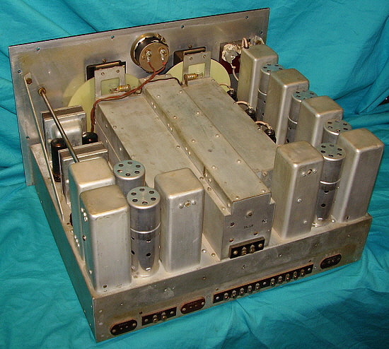
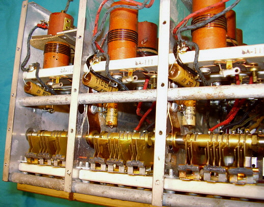
Disassembly: The best procedure to rebuild a Super-Pro is to start with a major disassembly. It will be necessary to remove the front panel and some of the assemblies for access to parts that need to be checked or replaced. There is no way to access the capacitors in the RF Tuning Unit except by its removal from the chassis and then removing its shielding. There is no way to remove the RF Tuning Unit (RF TU) unless the front panel is off. There are five paper wax capacitors located in the RF TU of the early SP-10 and SP-100 versions and three in the SP-200 versions. The early versions also have an RF shield between the RF and IF section of the receiver. It is easier to work in this section of the chassis if the shield is removed. In fact, it is easier to work on the chassis with the RF TU removed also. When the capacitors are replaced and the other rework completed, the receiver can be reassembled. On early models, if there is a problem with either the "On-Off" switch or the IF gain pot (Sensitivity pot on SP-100) you have to remove the front panel and the RF TU for access to remove these components. Check their operation thoroughly while everything is apart. | Capacitors: All paper wax capacitors should be replaced for best reliability and performance. Hammarlund did locate some of the paper-wax caps out-of-sight in the RF TU and in some of the AVC and Detector transformers but these are easy to access during disassembly. Whether you use "orange drops" or "yellow jackets" doesn't matter - both are much better capacitors than the originals were when they were new and, of course, now the originals have about 70 years of leakage to deal with. If you want to preserve the under chassis original appearance, then the new caps should be installed inside the original shells. This procedure is covered in the section below "Restoring the 100 Series 'Super-Pro.' Restuffing capacitors is, of course, only for aesthetic purposes. If under chassis appearance is not important, then install either modern orange drops or yellow jackets. You should use all of the same kind of caps when rebuilding a receiver. It looks professional. Mixed types of capacitors look like you were working out of your junk box! Military 'Super-Pro' receivers will have "bathtub" capacitors installed around the inside edge of the chassis. These are multiple paper capacitors installed in a metal box. Some of these are oil filled units. Also, some of the individual larger paper capacitors are also oil filled. If the oil filled units are not leaking oil, they are probably okay. They should be tested at their operating voltage for possible leakage if you plan on leaving them in the circuit. Or, you can just replace or rebuild each tub with new capacitors - your preference. |
Paper Wax Capacitor Locations: SP-10 - five .02uf, 400wvdc paper wax (pw) capacitors are located inside the RF TU. All other pw caps are under the chassis. SP-100
- three .01uf 400vdc and two .02uf 400vdc pw caps are located inside the
RF TU, two .05uf 400vdc and one .02uf 400vdc pw caps are located inside
the Amplifier AVC Output transformer, one .05uf 400vdc pw cap is inside
the Detector Output transformer. All other pw caps are under the
chassis. SP-400 - All pw caps are either .05uf or .02uf (all .01uf caps were changed to .02uf.) No tub caps. Hidden caps are the same as SP-200 for location but not necessarily value. |
Variable Coupled IF Transformers: You should check the variable coupled IF transformers for proper action. These have spring-loaded plungers that are operated by a cam and lever system. The Band Width/Selectivity shaft is also spring-loaded for a positive feel to the control. Most 'Super-Pro' receivers require a little bit of adjustment or rework on this "shaft-cam-lever-plunger" system to have the control function correctly, feel smooth in operation and to stay in place once set. A Bandwidth shaft that won't stay in position probably is missing one of the thrust washers. Add fiber or brass washers as necessary between the shaft thrust bearing and the rear bearing support. Usually only one washer is necessary to have the shaft stay in position. The variable coupled IF transformers require a delicate rework technique to avoid breaking the fragile parts. I have encountered both broken levers and broken coil-condenser mounts. Since these are made from fiber board, they are somewhat fragile. Care has to be taken when removing any of the variable coupled IF transformers from the chassis since there is an under the chassis coupling pin between the levers and the plungers. This is a "slip-in" type of coupling but any torque on the fiber levers will break the fragile slotted portion. If you have to disassemble one of the variable coupled IF transformers (to replace a grid lead or for some other reason) first remove the associated lever from under the chassis. When removing the shield (can) watch the spring that loads the center moveable coil mount. The top coil-condenser mount is held in position when mounted inside the can but when the can is removed there is nothing except the wire connection keeping the mount on the guide rods. The spring can lift the upper coil-condenser mount right off of the guides and launch the spring into the air requiring a search for its whereabouts. >>> | >>> Sometimes the upper coil-condenser fiber mount can become "jammed" and break the fragile fiber board holes that the guide rods pass through. During reassembly if any binding or tightness is noticed, don't force the assembly. Disassemble the IF transformer and you will certainly find that the top fiber coil-condenser mount is "jamming" on the guides and forcing the assembly would break the guide holes. If the upper and lower condenser mount screws go in without forcing, then check the plunger operation by hand from under the chassis. It should travel about one inch and should operate smoothly without binding. Mount the IF can shield to the chassis with the two nuts and washers, then check the plunger operation again. Sometimes the can has to be slightly moved as to how it mounts to the chassis for smooth plunger operation. Once the plungers all operate correctly, re-install the levers. They may require a slight offset in the angle that the lever engages the plunger slot. You can adjust this by loosening the mounting screw and adjust the lever for the proper angle and then retighten the screw. Normally, the plungers will rotate to allow further adjustment of the lever to slot engagement. On the SP-10 and SP-100 versions, the RF-IF shield has cut-out slots that the levers protrude through. Be sure that when aligning the levers to plungers that you still have the necessary clearance within the RF-IF shield slots. When everything is correct, the levers operate the plungers smoothly with no binding or sticking and with full travel. Generally, if you are careful and watch the levers, plungers and the load springs (and nobody else has been into the transformers before you to break things) everything will be fine. |
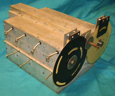
Other Components: Resistors should be checked for drift. Usually 20% is okay. On the early SP-10 and SP-100 receivers there are a couple of what look like adjustable trimmer capacitors. These are actually fixed caps that are the correct capacitance when the adjustment screw is tight - no adjustment necessary. The dial system is part of the RF TU assembly but the drive is by a "pinch-wheel" system that is mounted to the front panel. When the system is clean the tuning is super smooth. Dirt and grease somehow get in to the pinch-wheels and will cause a rough feel or even slipping. A good cleaning of the pinch-wheel and the rim of the dial will usually correct any problems and result in the super smooth tuning "feel" that the receiver had when new. >>> |
>>> On newer style pinch-wheels there is a nut on the back of the wheel that should be checked - it should be tightened when the dial edge is in between the pinch wheels. When reinstalling the RF TU, you will have to loosen or remove the pinch-wheel drives and then reinstall them after the RF TU is mounted. That way you can be sure that you don't damage the dials. If the Tuning Meter is open on the SP-10 or SP-100 series receivers, there will be no B+ to the IF section of the receiver. If an original meter can't be located and the defective one can't be repaired, it is possible to shunt the defective meter with a 2 ohm .5W resistor to get the receiver operational until a meter is found. |
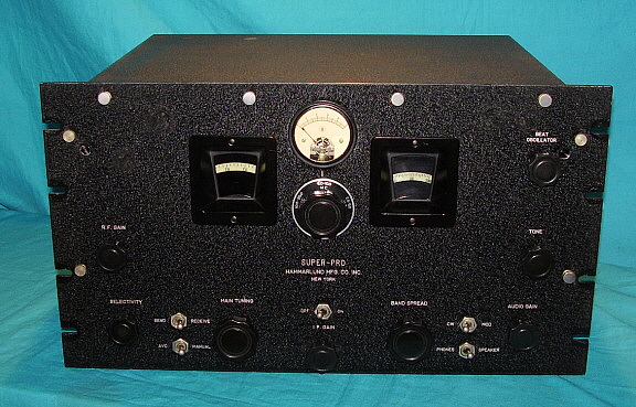
Front Panels: The front panel of early 'Super-Pro' receiver is made from .190" thick aluminum. It was wrinkled finished in black and then engraved so the nomenclature would appear bright silver. Only the front of the panel is painted - the back is always left bare aluminum. If the front panel doesn't have its original wrinkle finish it is next to impossible to restore the panel to original. Repainting the panel with wrinkle finish will fill in the engraving and then trying to "scrape out" the paint from the engraved areas by hand just doesn't work. The nomenclature usually doesn't look correct or "professional." The wrinkle finished panels were used on the SP-10, SP-100 and early SP-200 receivers. For best results with an original finish panel, clean the panel thoroughly and then touch-up as needed. Using Krylon Black Wrinkle paint (no longer available, use VHT Black Wrinkle Finish,) spray some in a small cup and then paint a thick coat with a small paint brush where the panel needs to be touched up. Use a heat gun to force the wrinkle - this will take a few minutes. Don't overheat the paint or it will "gloss" and not match the original. For very small areas, artist's acrylic "Mars Black" works quite well and some texture can be imparted to the touch up with a brush application. If you have an aluminum panel that is already stripped, paint it with Krylon Black Wrinkle Finish and after it has dried over-night, try digging the paint out of the engraving. Maybe it will work okay if the engraving is in good condition. Many panels that are stripped were done so by "sand blasting," or "grinding off" the paint. This removes a lot of material from the panel surface which reduces the depth of the engraving resulting in the problem usually encountered in trying to remove paint from the engraved areas. If the panel was chemically stripped you might be able to successfully restore the wrinkle finish and engraving. If the results are not to your satisfaction about the only recourse is to paint the panel with a smooth finish paint the then fill the engraving as described in the next paragraph. I always encourage restorers to try to save the original finish if possible. >>> | >>> The .125" steel panels, used on the SP-200 series from about 1941 on, are easy to restore. The panel front was copper-nickel plated and then a red oxide primer applied before the finish coat was painted. The back side of the panel is left unfinished. Since the nomenclature is stamped into the panel, the depression is much wider and somewhat deeper than engraving. This makes filling in the "lettering" easy after the finish coat has been applied and has dried. Original paint colors can be computer matched if some of the original paint is remaining. Professional automotive paint stores have the ability and the equipment to not only match the paint but to fill that paint into spray cans for easy application. Use a high quality acrylic enamel paint that is semi-gloss finish. Don't use bright white paint or white "lacquer-stix" to fill in the lettering. The nomenclature will look way too "bright." Instead, mix artist's acrylic white with raw sienna and just a little yellow to create a "beige" or "manila" color. This will look correctly "aged" for the fill. Apply to the lettering one control nomenclature at a time. Let it set for only a couple of minutes and then wipe with a slightly damp paper towel folded to be very flat. The "wipe" should be at a slight angle and only done once with that part of the damp towel. If more wiping is required, use a new unused section of the damp towel, otherwise you will get paint on the panel where you don't want it. When all of the lettering is finished, you can wipe down the entire panel with a clean slightly damp towel. Let the fill paint dry over-night and then apply Carnuba wax to the front panel (any non-abrasive wax will work.) Two applications will have the front panel looking great and with the patina of age imparted by the lettering not being "bright white." |
Cabinets: The early receivers just use a dust cover. It is black wrinkle finish and is secured with eight capped thumb nuts on the front and three thumb screws on the back. If the thumb nuts are missing, they are difficult to find anything like them today. They can be machined but this is expensive. You can make them from old nickel plated thumb nuts by filling the top of the hole with solder, them filing the solder flat. This usually looks okay until originals are found. The thumb screws are easier to find and usually not a problem. The SP-200 cabinets will have two chrome strips top and bottom. These can be missing or damaged. Unfortunately, they are difficult to replicate since they are thin sheet metal extrusion and chrome plated. Sometimes a cabinet will be encountered where the strips and handles were removed and the holes filled and the cabinet repainted. The military CH-104-A cabinet and the SP-400 cabinet did away with the chrome strips. The handles didn't change from the SP-200 cabinet to the early SP-600 cabinet. All are the same. The handles are easy to clean up and restore. The SP-200 and SP-400 will fit into either one's cabinet. Early rack mount SP-10 and SP-100 will also fit in any of the cabinets. Most of the SP-200 cabinets are black wrinkle finish while most military CH-104 and SP-400 cabinets are gray wrinkle finish. The SP-600 cabinet is dark brownish-gray wrinkle finish. >>> |
>>> When cleaning these cabinets remember they are durable and the paint is tough. They can take a lot of abuse without showing it. That's why I clean the wrinkle finish with Glass Plus and a brass suede brush. The suede brushes are available at shoe stores or sometimes shoe sections of regular stores will have them. The brass bristles are not very stiff and really feel somewhat soft. Get the section you are going to clean very wet with Glass Plus and then use the Suede brush in various circular motions, scrubbing the surface. Don't be overly aggressive but also you don't have to worry about the paint either. You will notice the wet residue will turn gray-black after a while. Wipe off the wet with paper towels. The towels will show a lot of color but it is mostly dirt. Repeat the cleaning until the paper towels are wiping off fairly clean residue. Perform the cleaning procedure on all of the cabinet surfaces and then let it dry thoroughly. After drying, do any touch ups now using either Krylon Black Wrinkle applied with a brush and force wrinkled with a heat gun (for areas over .5" diameter) or artist's acrylic for smaller areas or if it is a gray cabinet you're working on. Apply "3 in One" oil using a clean cloth after the touch-ups have dried. You may want to do two applications. Wipe off the excess with a dry clean cloth. The cabinet will look practically new with this treatment and it lasts quite a long time. |
Alignment: Any of the Super-Pro receivers are straight forward with no odd procedures or special equipment needed. The adjustment of the crystal filter may require a sweep generator and oscilloscope if the adjustment has been misaligned, but this is seldom the case. Since the adjustable 465KC IF transformers are over-coupled in the 16KC band width, the IF should be aligned in the 3KC position at the exact crystal frequency, if the crystal filter option is installed. Due to the extreme quality that was built into the tuning unit, all Super-Pros can be aligned to exceed the dial accuracy specification of 0.5%. If you can't achieve this accuracy then something is wrong with the oscillator section for that particular band. | Power Supplies and Power Cables: Early power supplies used standard can-type electrolytic filter capacitors. These are almost always dried out and need to be replaced. Even if they check good, they will certainly fail within a short time if you try to use them at full voltage. The original cans can be restuffed with new electrolytic capacitors or the new ones can be installed under the chassis. For aesthetic reasons, I place the new capacitor inside the original can. The military power supplies usually have oil filled paper capacitors for filters. Unless these have shorted or are leaking oil, they are okay to use. Some of the late version military supplies will have 12 can filter capacitors installed. These appear to be electrolytics but they are actually 4uf oil-filled paper capacitors. They seldom have any problems since they were of very high quality construction. Test them thoroughly before relying on them, though. The power supply has two large tapped wire wound resistors and it is very rare for them to have any problems. Many times the power supply will not be found with the receiver. They are fairly easy to find and almost any 'Super-Pro' power supply will work with just about any 'Super Pro' receiver. The power cable is also not usually with the receiver or power supply. The original cable is not an easy item to find so most collectors just make one. The only thing to observe is the wires #1 and #2 are a larger gauge, usually 14 or so, to provide a small IR drop across the cable for the tube heaters. The remaining wires are around 18 gauge and not critical as the current carried is low. The tenth wire, if present, is not used in the receiver circuit. It was a switched ground for optional user applications. |
|
Super Pro Modification Mayhem |
The Super-Pro is a terrific receiver - whether it be the
SP-10, SP-100 or the SP-200 series - they were the best of the
late-thirties designs. But, they are seventy year old (or more) receivers and, as
such, their performance is dated. The stock 'Super-Pro' was an
incredible performer. That is confirmed by the fact that the U.S. Army
Signal Corps versions of the 'Super-Pro' 200 Series are virtually
identical to the civilian versions. The military felt no need to modify
the SP-200 Series unless the receiver was going to be used for data
reception where stability and freedom from frequency drift were of
paramount importance. The military modifications were generally
professionally incorporated and enhance the receiver's performance. The
modifications discussed in this section are the professional "Geisler
mods" and the far more invasive and destructive CQ magazine "Surplus
Conversion" modifications.
As the owner of one (or more) of these great receivers, you probably want to experience what the original owner encountered when using the receiver when it was new. Something that is accomplished by a thorough rebuild and alignment of the receiver - not modifications. Understanding what the designers expected of the receiver and how they intended the receiver to be operated will help the new owner appreciate the vintage Super-Pro's capabilities. Of course, the original owner didn't encounter SSB signals but the Super-Pro will copy SSB without a problem if operated correctly. Drift, vague dial accuracy, etc.,...all pre-war communications receivers have the same characteristics. It's all part of the vintage ham gear experience that is enjoyed by so many collector-hams today. All serious collectors and knowledgeable hams agree that major modifications to vintage radio equipment in an effort to "modernize" its performance seems to go against the whole idea of collecting, preserving and operating vintage radio gear in the first place. Since the early SP-10 and SP-100 Super-Pro receivers were very expensive and sold during the time of economic recovery, they are normally not found in extremely modified condition. The SP-10 and SP-100 receiver usually weren't found on the post-WWII surplus market either. Most of the time, with these early versions, repairs and various component changes are all that are encountered. The unusual way that the SP-10 operates with its highly flexible front end and adjustable coupling in the Detector and AVC transformers has led to some SP-10s being modified to operate in a more conventional manner (rather than the operator "learning" how to use the receiver.) Most of the mods are to the RF Gain bias although anything might have been incorporated into SP-10 in an attempt to change its design characteristics. Most of these modifications are very easy to remove and return to the original configuration as most were wiring changes that didn't do any real damage. The WWII Super Pro, the 200 series in its various Signal Corps designations of BC-1004, BC-794 and BC-779, are the receivers that are usually found in "hacked up," unrestorable and non-functional condition. Cheap post-WWII surplus had something to do with this and also the belief in the myth that the "ham radio operator is a competent engineer/technician" promoted by CQ magazine. This combination lead to the destruction of many of the WWII Super Pro receivers. The following is how the Super Pro Modification Mania began. |
Louis E. Geisler Modifications - With the cheap, easy to find availability of the surplus WWII Super-Pro receivers in the mid-fifties and sixties, the "modification mania" did finally catch on and the WWII Super-Pro was considered "fair game" for modifications. Most of the infamous Super-Pro modifications were derived from the first of the series, "Souping the Super Pro" by L.E. Geisler, published in the Dec.1957 issue of CQ magazine. Geisler was an engineer that worked out of Japan for a company that sold modified Super-Pro receivers. Today, Geisler's modifications are "tame" and basically replace the 6L7 mixer tube with a different octal mixer tube that is quieter, then he replaces all of the capacitors and does a full alignment - pretty much standard stuff. Geisler's earlier mods are conservative, make sense, improve performance and do no real harm to the receiver. One has to remember that Geisler's company sold these modified Super-Pro receivers so they had to perform better yet still retain the professional-commercial appearance in order to have marketability. As time went on, Geisler's modification ideas evolved. Later Geisler-modified Super-Pro receivers will have more invasive modifications. |
Post-Geisler Modifications - The later modification articles go even further than the late-Geisler ideas with even more and more outrageous modifications. Included in the list of notorious "cut and hack" articles are "A Super 'Super-Pro'" and "SSBing the Super Pro" - both published in the "Surplus Conversion Handbook," part of the CQ Technical Series. These articles advocate the wholesale modification (destruction) of the entire receiver, including replacement of the front-end tubes with miniature tubes, an on-board solid-state power supply, removal of the 14 watt P-P audio section to install an anemic 6AQ5 single ended audio section (which also then provided room for the on-board power supply,) on-board converters to cover 10 and 15 meters, product and infinite impedance detectors - on and on. It's doubtful that a receiver could ever be returned to original after being the victim of these later modifications. I have only seen a couple of Super-Pros that attempted these modifications and they were wrecks. No doubt, the end product failed to impress the owners and the receivers were afterward relegated to the junk pile. Initially, I thought very few Super-Pro receivers had ever been modified since it was such a great design in the first place. The Super-Pro receivers that I had found around Nevada were mostly all original. However, after talking to several collectors in different parts of the country, it seems that there are lots of modified Super-Pros out there. Many modified versions are now showing up on eBay with all of them being non-functional and sold as "parts only." Certainly, the rarity of the particular example will dictate how far the owner is willing to go to restore a modified receiver to its original specifications. In a way, it's fortunate that the most common victims of the modification mayhem were the military receivers. They are also the most plentiful version around and that means that most of the SP-200 parts (many of which are interchangeable with SP-10 and SP-100 receivers) are usually easily available to complete a "restoration to original" on other Super Pro receivers that have fared better. It's unfortunate that the SP-200, especially the BC-779, were considered useless relics that were unusable "as-is" by hams and that, because of urging from CQ magazine and from the Surplus Conversion books, these great receivers were "hacked" to the point that now they are only useful as a "parts set." However, a true "Geisler Modification" or a "Military MWO Modification" receiver should be left "as-is" since these modifications made sense, were conservative in scope, expertly incorporated into the receiver and generally enhanced the Super-Pro performance. True Geisler mod'd Super Pros are rare, however. |
Using the Super-Pro as a Communications Receiver Today |
Some hams are reluctant to use a pre-war receiver in
actual "on-the-air" operations for fear that adjacent frequency QRM will
limit their ability to successfully copy stations and that they will be
unable to complete QSOs or Vintage Net operations. The Super-Pro might
have problems today coping with adjacent frequency interference from
powerful SSB signals when the user is trying to copy an AM signal (and
this will be the case for almost all vintage communications receivers.)
Even narrowing the "Bandwidth" IF passband or using the
crystal filter doesn't seem to help much. However, here's a couple of
"tricks" that work.
Probably the best way to "dodge QRM" is to tune the receiver slightly above or below the operating frequency. This, in essence, is selecting one sideband or the other of an AM signal, whichever has the least QRM. Most SSB transceivers have filters to keep the transmitted bandwidth at about 2.1kc on one sideband only. Most AM signals are at least 6kc bandwidth with audio information contained in two sidebands. It's very easy to tune the offending station "out of the passband" and still recover enough audio for solid copy of an AM signal. >>> |
>>> Additional selectivity using the crystal filter will also help to reduce
the ratio of adjacent frequency interference to tuned signal. You'll
have to tune the desired signal "on the nose" for good copy. Broad,
high fidelity audio fidelity cannot be enjoyed using either of these QRM-reduction modes. But,
the goal is successful copy and a completed AM QSO, in other words -
communications. What about in actual use? I use only vintage receivers for operations on the ham bands and I find that regardless of the model of vintage receiver used, these two methods all but eliminate most adjacent frequency QRM. You'll still probably hear slight indications of adjacent frequency activity but copy will be 100%. Of course, it isn't enjoyable, "arm-chair" copy but it is a successful completion of the QSO or of the net operations, which is the goal. |
Restoring Pre-War Super-Pro Receivers The following are write-ups of pre-WWII Super-Pro restorations. The SP-10 write-up is from 2008 and the SP-100X write-up is from 2007. In Part 3 is the write-up for the SP-100LX, from 2019, so it's in a different style. For the past few years I've done these restoration write-ups as journals that track the day-to-day progress of the restoration. Of course, sometimes there are inevitable delays and sometimes these delays might run into several months or even years. At any rate, the SP-100LX restoration write-up is a journal-type and that allows the reader to become aware of how much time is spent on finding proper parts or special materials necessary for a proper rebuild. Also, the time it takes to accomplish the tasks involved once all of the parts become available. - May 2019 |
Restorating the WMI-Hammarlund 'Super-Pro' SP-10 SN: 576 |
photo left: The WMI SP-10 before restoration |
The Hammarlund SP-10 SN: 576 is a rack mount version of the first version of the Super Pro that was used at WMI, a ship-to-shore station on the shores of Lake Erie. I found the receiver listed on QTH.COM. in January 2008. Its purchase included an original SP-600 cabinet thrown-in. Unfortunately, shipping ran about 55% of what the price of the receiver and cabinet was but it was safely packed and arrived without any issues. Initial examination revealed that the condition was very good cosmetically but the under chassis was almost totally non-original. I knew the receiver had been used extensively at WMI and had seen detailed photos of the underside so this was no surprise. I knew what I was going to be getting into. At first, I thought I might be satisfied with the SP-10 given its WMI
provenance but closer examinations kept revealing more and more late,
post-WMI components and mods. I noted that almost all of the installed
capacitors were Vitamin-Q types date coded 1973 (about ten years after
the receiver left WMI.) I came to the conclusion that about half of the
receiver circuitry modification was not WMI's work and that only the
visible front panel mods were the remains of WMI "hacking." |
This was going to be a thorough, "ultimate museum quality"
restoration using rebuilt capacitors in original paper-wax shells,
original type resistors where needed and authentic Hammarlund
parts from other Super-Pro parts sets. We even used some of the original
Hammarlund wire from the parts sets. We were going to strictly adhere
the original Hammarlund wiring layout and to match exactly the original
circuit design - taking into account that there were two original
Hammarlund engineering upgrades not on the SP-10 schematic that had to
be left in place. During the restoration, every step was guided by the
desire to have this SP-10 be the most authentic, best representative of
how the Hammarlund SP-10 appeared and functioned when it was new in
1936. To guide us, we used our experience gained during our "museum quality" restoration of the SP-100X SN:3387 receiver along with the evidence found during the SP-10 disassembly, the under chassis artwork in the SP-10 manual and the SP-10 and SP-100 schematics as references. Hopefully, this would result in a very authentic, restored SP-10 that could be used as a reference for how these receivers were built, how they performed and how they looked - both externally and internally. |
The Planned Restoration Work |
I had never encountered a receiver that had so many
deviations from original wiring layout, in component placement or
component type but that was still functional and still looked decent.
This was primarily due to the WMI repairs done over the years. Since the
receivers were used 24/7, repairs must have been a somewhat regular
necessity. Originality was not a concern and neither was neatness. The
end result of years of use and repair cycles is a receiver with very few
original parts, several wrong value parts and many modifications to
component placement or layout with some circuitry modifications thrown
in. A lot of later post-WMI work was also performed on the receiver,
also with little regard for originality. Here is the list of the
deviations from original. A. AC Power switch disconnected and wires connected to "Speaker-Phones" switch instead - repair of defective AC power switch B. Send/Receive switch has another set of wires running back to the "Phones" terminal output - runs stand by switch operation to rear of chassis C. 500-8 ohm transformer installed on inside wall of chassis connected between audio xmfr and spkr term. (matched 8 ohms standard audio output Z to 500 ohms Z) D. Shielded cables run from 500/8 xmfr to front panel phone jacks and to speaker terminals (allows phones use since the rear terminal was S/R function) E. Two phone jacks installed on front panel marked inside panel as "600 ohm output" - brings audio output to front F. E-W antenna switch front panel mounted - for switching directional antennas at WMI but was unwired G. SO-239 front panel - connected to back antenna input terminals with RG-58 cable - part of antenna switching that was disconnected H. #47 lamp sockets installed - should be #40 lamp sockets - "hamster mod" because of difficulty finding #40 lamps |
I. Dial window indexes not original - look crude and home made J. Tuning Meter is non-original movement inside original housing with repro scale - meter repair that was actually fairly well done K. RF Gain mod per W4QCU - overloaded on strong sigs - two wires moved, not invasive L. All small knobs were not original types - unknown reason M. 42 tube socket replaced with bakelite type - burned up original? N. Grounds are all connected together with small gauge wire - unknown reason O. Small gauge plastic insulated wire used to connect 1st IF transformer to circuit - earlier repair? P. Shielded cable from detector to BFO - non-original cable (modern) - original may have deteriorated Q. BFO grid cap was 500pf, should be 100pf - repair with wrong value part - may have been WWII repair when parts not available R. Screen load on 2RF amp was 2.4K should be 5K - repair with wrong value part - may have been WWII repair when parts not available S. 220 ohm resistor added to B+ line to CT of audio output xmfr plate winding - to lower B+ from +385 to +365vdc at the 42s - allows using SP-100 PS T. Though minor, someone wrote in black marker ink all of the circuit functions on the inside of the chassis. Additionally, dymo-lables were on the RF box indicating alignment functions. Also, all of the IF and AVC transformer cans were marked with marker ink. - Who knows why? Probably someone thought it would save time in troubleshooting if the circuit and component functions were obvious. |
Planning and Finding Parts: I waited about 2 months before starting the restoration. This gave me time to do research, studying and planning of how to accomplish the rework. I was going to need 35 paper-wax capacitors to build the replica capacitors. The original paper-wax caps had been replaced eons ago but I wondered if the "hackers" had ever gotten into the RF box. When disassembled, I found three of the five capacitors were indeed originals. They were Aerovox brand, which meant I would have difficulty in finding enough correct vintage shells. After searching only turned up five or six correct style Aerovox shells, I decided I might have to go to Cornell-Dubilier TIGER brand, as they were standard originals for the SP-100 and later receivers. Fortunately, in searching around I made an important discovery. While looking at a junker HQ-120 receiver to harvest C-D caps, I noticed that the original capacitors were intermixed Aerovox and C-D brands. I was positive all the capacitors were original. I had discovered a precedent that Hammarlund did intermix capacitor brands sometimes, so I would do the same thing with the SP-10. Five Aerovox shells would be used where the caps mount on the tube sockets, three original Aerovox shells would be used in the RF box and all the other capacitors would be Cornell-Dubilier TIGER brand. | The Importance of Having Parts Sets: I had serious doubt that the SP-10 dial windows with index line were original. They were a crudely made lamination of plastic and the scribed index wasn't even straight. I convinced myself of their non-originality when I pulled apart the laminate and the glue was still somewhat tacky. Luckily, I had an SP-200 parts set. This poor receiver has served its fate as a donor for three different Super-Pro restorations and it was nearing its end as a useful "parts set" since there were very few parts left on the chassis. But, even though most of the parts were missing, this receiver supplied dial masks, dials, both dial window indexes, AC power harness, IF transformer parts, correct dial lamp harness, a multitude of screws and washers, some knobs, some wire and some meter parts. Additionally, an HQ-120 junker supplied many Aerovox and C-D capacitors. The junk box supplied a correct style fiber tube socket with the correct "42" ID, several of the correct style/value resistors. Without these junk sets and several junk boxes to rob parts from I doubt that the SP-10 restoration would have ever started since correct authentic vintage parts are so difficult to find. |
The SP-10 Restoration Work |
The photo to the left shows the front panel before restoration. The physical modifications were going to be difficult to repair. Most of the time, amateur modifications have little regard for symmetrical layout or quality machine work. The WMI SP-10 mods, even though performed by "professionals," were very much like amateur workmanship. I knew from an earlier restoration of an SP-200LX receiver with a repainted aluminum front panel that stripping and repainting wrinkle finish on this aluminum panel would be a disaster. Trying to remove the paint from the engraving is next to impossible. Touch-up is the only method that preserves the original look of the receiver panel. Filling the holes presented a challenge because of their size. First, the panel was thoroughly cleaned using Glass Plus and a brass "suede" brush. This is done to clean the smoke and grime out of the engraving so it would look silver again. The only practical hole repair method was an epoxy fill. I placed masking tape over the holes on the front side of the panel and then backed that with blocks of wood clamped to the panel. This gave a very flat surface and the masking tape assured that the epoxy would not stick to the backing blocks. I fill from the back side using slow curing epoxy to make sure all of the bubbles have a chance to rise to the surface (the back of the panel.) Because of the thickness of the panel, two layers of epoxy were required for the complete plug. The epoxy was left to cure overnight and then the blocks and tape were removed. This leaves a super-flat surface on the front of the panel. The back side is leveled using a Dremel Tool. The front side is painted using Krylon Black Wrinkle finish applied with a brush and "wrinkled" using a heat gun. Only the plug is painted and if everything goes okay, the match is virtually undetectable. The backside was painted with silver paint. |
|
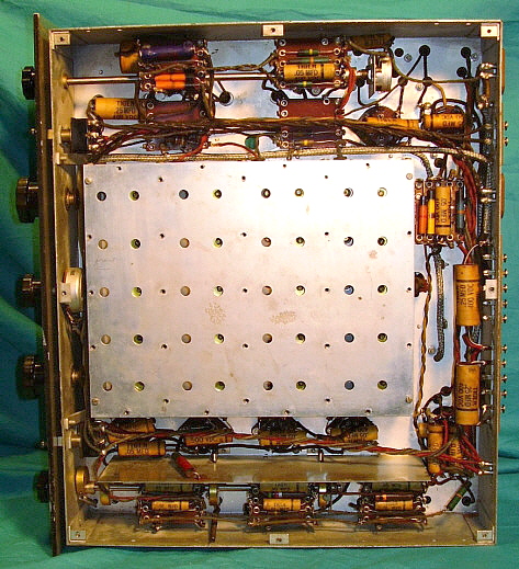
The photo to the left is a shot of the chassis underside
before restoration. There was so much that was non-original I created a
list to keep track. Some of the notable deviations under the chassis -
the shielded cables routed next to the RF box. These carried the audio
output to the phone jacks mounted on the front panel. The transformer
matched the 8 ohm Z output of the receiver to the 600 ohms required at
WMI. None of the capacitors are original, most having been installed in
the 1970s after the receiver's tenure at WMI. Many modern style
components were installed in the various circuits. The photo to the
right shows the SP-10 underside after restoration to original. The
wiring layout follows the under chassis drawing in the SP-10 manual and
also required several references to the SP-100 receiver. This was to
assure that all wiring and component placement matched what was done at
Hammarlund. |
|
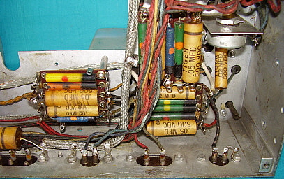
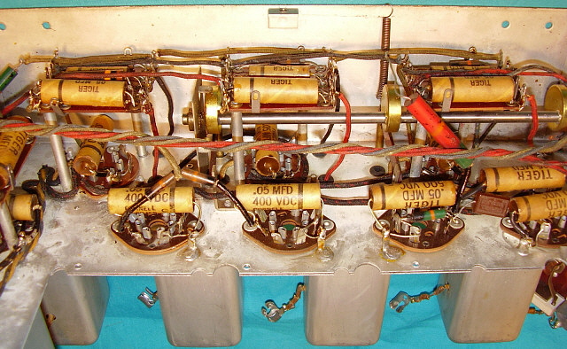
The close-up photo to the left shows the AVC and BFO sections with
rebuilt capacitors and replica resistors. These rebuilt capacitors
happen to all be Cornell-Dubilier TIGER brand. This receiver restoration
was different in that I had to find all of the shells first. This
allowed me to rebuild the caps ahead of actually installing them. This
seemed to make the job go much faster because I could do several
capacitors at one time. Even so, the time per capacitor still was about
ten minutes. My method is to use a heat gun to melt out the original
capacitor and then wipe the shell with a paper towel to clean it. I then
install a film capacitor of the correct value and correctly oriented and
secure it with hot melt glue. After the glue has set-up, I fill each end
with brown sealing wax. The end result is a capacitor that is new but
difficult to distinguish from an original. The two 60K resistors are replicas that are repainted to match the BED coded originals. There were several JAN type resistors installed and even some modern metal-film resistors that were removed. To keep everything looking the correct vintage I used similar to original size and shape resistors of the correct value. These similar style resistors were marked in banded color codes. Also, some of the replacement resistors found had leads that were too short for the Hammarlund "thru-the-eyelet" type of mounting. I had to carefully add a length of TC wire to be able to mount the resistors correctly. When the leads were installed, I then painted the body of the resistor in the BED code style. When mounted, only a close inspection reveals that these are replica resistors. |
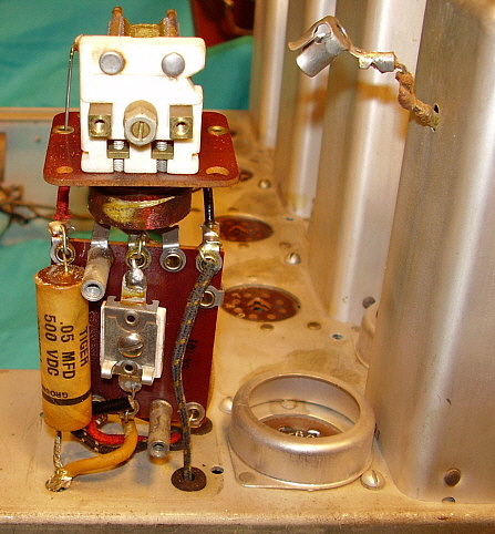
I initially installed the three IF screen bypass capacitors as the replacement, non-original caps had been installed - on top of the component board. This had the capacitors on top of the 10K resistors. This didn't seem likely and I remembered that in the SP-100 rebuild, the IF screen caps had been mounted at the tube sockets. Looking at the manual drawing, it was apparent that the caps shouldn't have been mounted on the component board. I removed them and moved the component boards in order to have access to the IF amp tubes. There I found the evidence I was looking for - the actual remains of the original capacitor leads left behind when the receiver was re-capped years ago. I installed the rebuilt caps at the tube sockets, as was original manufacture. The photo to the right shows the RF-IF section with all rebuilt capacitors installed in their correct positions. The Aerovox rebuilds installed in the RF section can be seen. The LO capacitor that looks like an adjustment trimmer is actually a fixed capacitor that is the correct value when the screw is tight. Though this one is a replica I made, it is very close to the original in size, value and appearance. |
|
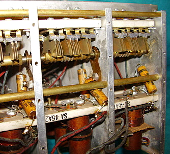
The photo to the left shows the bandspread condenser side of the RF
Tuning Unit and the rebuilt paper-wax capacitors. These five capacitors
are completely hidden and require the removal of the RF TU from the
chassis and then the removal of the side covers to access the capacitors
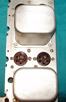
for replacement. The photo to the right shows the replacement fiber tube
socket (the one on the left) that was installed to replace an incorrect
bakelite socket that had been installed in a repair done many years
before. Luckily, I found an exact style fiber socket with the correct
"42" tube ID in one of my junk boxes. Nowadays, we probably shouldn't
call them "junk" boxes since the parts they contain are so necessary for
restorations and are so difficult to find otherwise. None of the grid leads were the correct, rubber insulated wire. The correct color is cream. I found that the old style large gauge round AC power cables use rubber insulated wire and the neutral wire is a creamy white color rubber insulation material that provided a good match for the original grid leads. Fortunately all of the grid caps were original and were reused for the new grid leads. In addition to the rubber insulated grid leads, there were two shielded cables that needed to be rebuilt. The output cable from the Detector to the First Audio stage had deteriorated and was on the verge of shorting. By using the same rubber insulated wire I was able to "push thru" a new center conductor that looked just like the original. A replica shielded cable had to be made for the BFO output to the Detector cable. This had been a piece of modern phono cable which we replaced with a replica that matched the original style. |
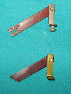
photo above: the variable coupled IF system levers. The top one is good, the bottom one is broken |
Rebuilding the Variable Coupled IF Transformer System: I noted that the Selectivity control shaft did not stay where set and that the action felt very loose. Inspection revealed that two of the three levers were broken and were not even moving the IF plungers. Removal of the variable-coupled IF transformers showed that earlier repairs had broken the fiber board guide holes on two of the transformers. The parts set provided the necessary replacement parts including two good condition levers. See the section "Guide to Restoring Super-Pro Receivers" in this web article for more details on general rebuilding of the variable coupled IF section. Tuning Meter: The Tuning Meter has a more modern movement that replaced an open coil original. The case and glass are original. It was necessary to install a shunt inside the meter case so that the meter would have the proper range. This had to be selected after the receiver was operational since there are no specs for what the original meter movement was. Testing showed that 7.0mA fs gave the best action and range. If I can ever find an original functional meter for either an SP-10 or SP-100, I will replace this meter since it is not totally original. Replica Dust Cover: The original dust cover had been discarded many years ago by WMI. I tested the fit of the dust cover from my SP-100 and found that it fit perfectly. I bought some 20 ga. sheet metal and did the layout for the dust cover. I carefully cut out all of the vent holes and marked all of the bends necessary. I had a local sheet metal shop do the bending and spot welding. The replica fit perfectly when I got it back from the shop. Next, I had to make the studs out of 8-32 threaded stock. I didn't have the necessary small rivets used originally to hold the studs in place. Instead, I used 2-56 screws and nuts to secure the studs. I did modify the screw head to look like a rivet. When installed only the nuts inside give away the fact that these are replicas. I was lucky that fellow ham KØDWC had some of the original 8-32 cap nuts and I made the rear 6-32 thumb screws. Painting was all that was left. The inside was painted gloss black and the outside painted with Krylon Black Wrinkle finish that is "baked" to force the wrinkle. The finished cover is next to impossible to distinguish from the original, except that it doesn't have the rear ID plate - but I did drill the holes so it would look as if one was there at one time. |
photo right: the finished WMI SP-10 chassis which also shows the variable coupled Detector and AVC transformers |
|
Final Testing and Alignment: I modified a late manufacture SP-100 power supply to use with this SP-10. By installing a 250 ohm 5 watt resistor between the +385vdc supply and the PS output terminal, the voltage is dropped to about +360vdc at the SP-10's P-P 42 audio output tubes. The other voltages are the proper level for an SP-10. The late SP-100 PS was the one that came with the SP-10 and probably had been with the receiver for a considerable period of time. Being a late build, this PS had a filter choke installed to sub for the speaker field which allows the use of a PM speaker. I also was using an SP-200 power cable which has larger tube heater wires for a smaller IR drop across the cable. Upon power up there was no signal, just audio hiss. Within a few minutes the smell of "hot resistor" was noted and the power was shut down. The Mixer plate load resistor had gotten very hot but what caused it was unusual. The wiring for the tube heaters in the SP-10 is unconventional in that some of the heater wires pass over the tube sockets instead of around them. In this case the plate pin of the Mixer tube was contacting the heater wire and the insulation was thin or gone - anyway, a short occurred and caused the hot resistor. I moved the wire and then applied a paint on insulation (black) to assure the problem didn't happen again. Power was again applied and this time the SP-10 burst into a wonderful audio sound experience. I was amazed by the sound quality of the AM BC station that happened to be tuned in. Unbelievably wide range, bass-laden music. I was impressed. Not that there weren't some minor issues, though. I still had to set the shunt in the Tuning Meter and perform a full alignment. After that, the audio from the SP-10 is just fabulous. It sounds very bassy and wide range when receiving AM BC or SW BC when conditions allow for great reception of the South America SW stations that play music. AM hams that run some power sound incredible. The entire operation of the receiver is exactly as described in the SP-10 manual and certainly a pleasure to listen to. Trying to imagine what an original owner must have thought of his new Super-Pro in 1936 is always interesting - too bad they were so expensive that few hams could afford them in 1936. Certainly signals are quite different today, but still it must have been thrilling to receive shortwave stations from around the world on a then new Super-Pro. |
Restoring the 100 Series "Super-Pro" - SP-100X SN: 3387 |
I owned this 1937 SP-100 for about four years before I decided to restore it. It was an e-Bay purchase that happened to have been offered by a seller that was located only about 25 miles away. I e-mailed, asking if I could come over and look at the receiver before I bid on it. The seller was more than happy to agree so I drove down to Gardnerville, Nevada to have a look. The SP-100 was in good physical condition and was complete with the matching serialized power supply. I bid on it and won. So, with another trip to Gardnerville, I became the owner of this great receiver. I didn't expect it to work and a quick check over found several things that needed to be repaired before it was powered it up. I only did "quick fixes," just to see how the receiver would perform. I used the receiver a few times but never trusted it with long operating stints. I had planned to restore it long before I actually did - but delays on projects seem to be the norm around here. At the end of 2007 I finally got some time to do this SP-100. A detailed inspection of the chassis showed that many capacitors had been replaced over the years - mostly using Sprague molded caps similar to "Black Beauties" but without the color-code stripes. Some of the resistors had also been replaced since they had burned up when the original associated capacitor failed. All of the other parts,...IF transformers, AF transformers, the meter, etc. were all original and in good operational condition. I wanted to perform a "museum quality restoration" on this SP-100 as it was an excellent example of this rare receiver. Our "museum quality restoration" results in a fully functional receiver using the original design circuit with the entire appearance of the receiver as close to original as possible with the patina of age preserved. The under chassis appearance has to look original, therefore all capacitors are "re-stuffed" with new film caps inside the original capacitor shell. Any resistors that are replacements have to be the original style part. Any defective parts are rebuilt and if that is not possible, a correct style and manufacturer part is used as a replacement. When the rebuild is completed, the receiver is fully tested and aligned. The completed receiver can be used as a reference, illustrating how the originals looked - on both the exterior and the interior of the set. Also, I had wanted to document the performance of this receiver, so it was necessary for it to function reliably at its design limits. photo right: the restored SP-100 chassis - note the differences in this chassis and the SP-10 chassis. The lack of adjusters on the Det and AVC transformers, the metal octal tubes used and the different style audio transformers. Also, note that SN: 3387 is a "table model" version with an 18" wide panel and no rack mounting slots. |
|
photo above: The bandspread condenser side of the RF box showing the "hidden" paper-wax caps inside. Note the Isolantite material used for the coil mounts and the variable condenser mounts. This was a low loss ceramic material. |
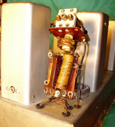
Rebuilding Capacitors When checking the schematic, the parts list shows that 35 paper-wax capacitors are used in the SP-100 circuit. But comparing that information with what can be seen under the chassis, it becomes apparent that nine capacitors seem to be missing. They aren't - they are located inside the RF box, inside the 2nd Detector Output Transformer and inside the Amplified AVC Output Transformer. The RF box caps are difficult to see let alone replace. Disassembly of the RF box is necessary to have easy access these five capacitors. Unfortunately, you can't just remove the side covers - you have to remove the entire RF box from the chassis first. This isn't as difficult as it sounds - eight wires must be disconnected, the front panel removed and 10 mounting screws taken out to remove the RF box. |
photo above: The completed RF box fully assembled and ready to install. Note the new grid leads and grommets. There are 33 screws for the bottom shield, 20 screws for the two top covers and 8 for the back covers along with the 50 screws for both side covers. Total of 111 screws just to hold the shields and covers in place. |
|
There are also three paper-wax capacitors inside the
Amplified AVC Output Transformer. In the photo to the left the .02uf and
one of the .05uf caps are visible. The other .05uf cap is on the
backside of the fiberboard mount.
There is one remaining paper-wax capacitor inside the 2nd Detector Output Transformer. It is a .05uf shown in the photo to the right. What appears to be trimmer capacitors are actually an assembled fixed capacitor. There is one on the back of the board also. When the screw is tight, the capacitance is at the required value. These are original and are Hammarlund parts. Behind the board was a 5K ohm resistor that was burned and measured 1K ohm. This was replaced with a correct vintage part. Also shown in the photo to the right is the deplorable condition of the grid leads. More on this problem below. |
|
Since more than half of the original paper-wax capacitors had been replaced in the past with plastic molded style caps, I had to locate 18 Cornell-Dubilier "Tiger" paper-wax capacitor shells with the correct values to build my restored caps. I had an old SP-200 parts set that became the "donor" for these correct capacitor shells. I use a heat gun to melt out the old original cap leaving just the shell. I wipe the excess wax off while the shell is still hot to clean the surface. I then install a new metalized-film capacitor of the correct value inside the shell. I orient the caps all in the same direction with regard to the outer film marker on the shell though it really doesn't matter with modern film caps. I secure the new cap in place with hot melt glue and when that has cooled enough, I fill each end with brown colored sealing wax. The whole process takes about 10 minutes per capacitor. The results are shown in all of the under chassis photos - all of the paper-wax capacitors shown have been rebuilt. I install the rebuilt caps in the proper direction. This whole process is for cosmetics, it does nothing to help performance. If under the chassis appearance is not important, then just install the correct value, modern capacitor. It is easier to work on the SP-100 chassis if the RF box is removed - you have to do this anyway to replace the five capacitors located inside. Also it is easier to work on the RF/IF section if the shield between those two sections is removed. The photo to the right shows the RF/IF area of the chassis with the shield removed. Also to access the bypass caps on the IF amplifier tubes it is easier if the small fiberboard component mounts are placed out of the way by removing the mounting screws and a few of the wires. This allows open access to all of the parts that need replacement. There are nine of these small fiberboard component mounts under the chassis but only the three over the IF amplifier tubes need to be moved. |
|
photo above: The Crystal Filter assembly with new grid lead and new connecting wire for the Phasing Condenser and Crystal. |
Other Restoration Work Once all of the capacitors were rebuilt, it was necessary to replace all of the grid leads from all of the IF transformers and AVC Output Transformer and the BFO coil. The Crystal Filter assembly is rather complicated in its construction and was removed from the chassis in order to easily disassemble, replace the grid lead and the connecting leads to the crystal and the phasing condenser and then reassemble. These grid leads were originally rubber insulated stranded wire but the rubber had become "lumpy" and had hardened, becoming brittle. Any flexing would break the rubber off of the wire. I used a cream colored cable jacket that was off of old telephone hook-up cable (I now use the cream-color, rubber insulation found on the Neutral wire in AC power cables - much easier to find and looks correct.) I stripped the outer jack off and then inserted a stranded wire into the jacket to build grid leads that had the correct feel and looked pretty close to the original. I was able to reuse all of the original grid caps. All new rubber grommets were installed also (I now don't install grommets on the IF and AVC cans as it appears that they weren't used originally.) All resistors were checked for value and all were found to be within 20% of the correct value except the burned resistor in the 2nd Detector Output Transformer. While most of the assemblies are off of the chassis is a good time to clean the chassis. I just used Glass Plus and a horsehair brush since the chassis was in good condition. Also, this is a good time to thoroughly check the Sensitivity potentiometer. This part cannot be removed when the RF box is installed. In fact, replacement of this part normally requires removal of the front panel and the RF box to accomplish, so now is the time to check it (this is also true of the "ON-OFF" toggle switch.) I disassembled the Sensitivity pot and cleaned it but it was going to become a future problem after re-assembly. |
photo above: The underside of the chassis complete except for the 33 screws that hold the bottom plate on the RF box. Also note that there is absolutely no clearance behind the Sensitivity pot if it needs to be removed. Same goes for the "ON-OFF" switch. |
At this point the receiver was ready to reassemble.
When replacing the RF box, the two pinch wheel drive housings have to be
loosened and then the two dial edges guided in between the drive wheels
as the RF box is placed on the chassis. Once the dial edges are engaged
then the pinch wheel housing can be retightened and the dial drives
tested. There shouldn't be any slipping and the drive should be
ultra-smooth. Then the screws that hold the RF box can be tightened. The
idler gear for the dial mask drive needed to be mounted and adjusted -
the assembly can be moved vertically for centering the dial mask and
then the screws tightened. When the front panel is bolted in place then
the Crystal Filter panel can be mounted followed by all of the knobs and
the tuning meter. I tested all of the tubes and found them to test fine
- at least in the tube tester. The receiver was now ready to test and
align. I had a couple of problems turn up after a short period of
operation. First was a noisy 6B7 tube in the detector stage. This showed
up as a continual but erratic "rushing-thumping" noise that varied with
the AF Gain control. Second was a "noisy" 6F6 in the push-pull AF stage.
This showed up as soft, weird noises (erratic audio oscillating) that
was present even when the AF Gain was reduced to zero. I guess this
shows that even the best tube testers don't catch everything. During the alignment another problem showed up. Audio distortion was noticeable while in AVC and the Sensitivity control didn't reduce the RF/IF gain when the receiver was in AVC. This problem was caused by a bad solder joint in the AVC line to the RF amplifiers and an intermittent Sensitivity pot that ultimately had to be replaced. The finished SP-100X has fabulous audio with plenty of power, formidable bass and a very wide audio response when in the 16KC IF bandwidth. Excellent dial accuracy - easily better than the 0.5% specification. Sensitivity is at the limits of what antenna noise is present and selectivity is sharp in the 3KC bandwidth and ultra sharp with the Crystal Filter. AM-BC and SW-BC stations sound incredible. Vintage AM Ham stations that run some power (like retired AM BC transmitters) are a pleasure to listen to. Simply a great receiver. |
photo above: The finished 1937 SP-100X sn: 3387 (ps is sn: 3388) |
Pre-War Super Pro Part 1 Return to Home Index
|
Radio Boulevard
Western Historic Radio Museum
Vintage Radio Communication Equipment Rebuilding & Restoration Articles,
Vintage Radio History and WHRM Radio Photo Galleries
1909 - 1969
- 60 years of Radio Technology -
This website created and maintained by: Henry Rogers - Radio Boulevard, Western Historic Radio Museum © 1997/2025