Radio Boulevard RACAL
|
RACAL |
|
Racal Ltd.
was a British company that was founded by Raymond F. Brown and
George "Jock"
Calder Cunningham in 1950. The company name was derived from their
names, RAy Brown and Geo. CALder Cunningham.
In 1950, both Brown and Cunningham had quit their jobs at Plessey Company, a large British electronics firm, to start their own electronics business. Both men put up about £ 50 each to get their business started. Initially located in Isleworth, West London, within a year the company became Racal Engineering Ltd. When Racal business was slow, as it often was at first, they would build things other than electronics, such as golf clubs or shelving units. In 1954, Racal moved to their commonly known location, Bracknell, Berkshire, which is west of London. |
|
RACAL, The Royal Navy and the Collins 51J Receiver
If Racal was going to build copies of Collins' 51J, they would have to be licensed by Collins to do so. Naturally, Racal wanted to use mostly British parts (probably so did the Royal Navy) but Collins Radio Company insisted that only parts from the USA could be used and only receiver assembly could be performed by Racal. Ultimately, the proposal ended up with a group from Collins doing an inspection of the (then) small Racal manufacturing facility. Apparently, Collins wasn't impressed and simply refused to license the manufacture of the 51J by Racal. The only option left was for Racal to design their own receiver that would meet the requirements for the Royal Navy contract. Racal contacted Dr. Trevor Wadley to help with the project. |
|
RA-17 Development and RACAL Evolution |
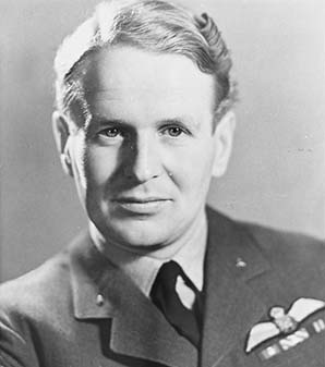
Dr. Trevor Wadley,
the Wadley Loop and the RA-17
- Dr. Trevor Wadley was a well-known, South African electronics
inventor and engineer. He had a near-eidetic memory and rarely
took any written notes. During WWII, Wadley had worked on
British Radar systems. His well-known inventions were the
Ionosonde, which measured characteristics of the Earth's
ionosphere. The Wadley Loop, that is mostly widely known for its
first use in the Racal receivers but was also later used in the
Barlow-Wadley XCR-30 receiver. Wadley's generally best known
invention was the Tellurometer, a portable device that precisely
measured land distances by timing a microwave signal propagation
delay. Until lasers became commonly-used surveying tools, the
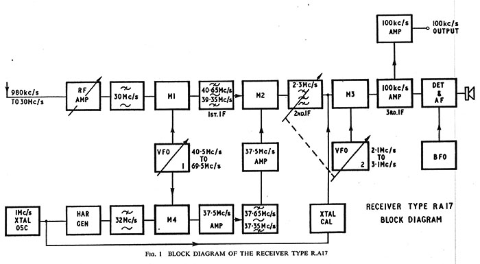
Tellurometer was the most accurate land-distance measuring device. For the Racal receiver project, Wadley proposed using a circuit that he had developed in the 1940s for test equipment (and that Dr. Wadley was planning on incorporating into a receiver design of his own,) as the basis for the new receiver. The "Wadley Loop" became the "heart" of the new Racal receiver design because it radically transformed what was then typical of a "non-Collins" receiver's inability to successfully and accurately copy RTTY (called RATT in UK) signals and other data transmissions that required virtually "no drift" in the receiver's frequency control circuits. The Wadley Loop allowed the new Racal receiver perform like a Collins 51J, with superb frequency stability and 1kc dial readout accuracy, but doing so with an entirely original design. The Wadley Loop virtually eliminated frequency drift by using a combination of one fixed oscillator, one VFO and three mixer circuits. Note the block diagram shown to the lower right. First, a 1.0mc crystal oscillator feeds a harmonic generator that produces strong multiple 1mc harmonics that are used to create thirty selectable 1mc wide tuning ranges. This "comb" of harmonics are fed into Mixer 4 and combined with the output from the MC/VFO which tunes 40.5mc to 69.5mc. Simultaneously, the RF input signals are fed to Mixer 1 and combined with the output from the same MC/VFO output. The output of Mixer 1 tunes from 39.35mc to 40.65mc and feeds Mixer 2. Also simultaneously, the output of Mixer 4 goes to a 37.5mc amplifier, a bandpass filter and then another 37.5mc amplifier with its output also connected to Mixer 2. The "drift cancelling" happens because "Mixer 1 + the MC/VFO" and "the MC/VFO + Mixer 4" are the inputs to Mixer 2. If there's a frequency drift of, for example, 2kc in the MC/VFO, that frequency drift is seen in both Mixer 1 and Mixer 4 outputs (+2kc.) The Mixer 2 output is the difference of the two inputs (both +2kc) and still results in the 2-3mc IF. Since the drift is added simultaneously to both inputs of Mixer 2, the resulting output frequency doesn't change since the difference remains the same, thus the drift is cancelled. Or,... (Mixer1f+2kc drift) minus (Mixer4f+2kc drift) equals Mixer2f+0kc drift. |
|
Rinus Jansen
gives the best detailed explanation and shows a better
mathematical example of the Wadley Loop function.
This except is from his "The Racal Handbook"
and
is quoted next. "Let's assume we want to receive a signal of 12Mhz. This 12Mhz goes through the two low-pass filters and the RF amplifier and arrives at Mixer 1. The Mhz VFO (VFO-1) is tuned to 12Mhz thus resulting in an output of 52.5Mhz. The output to the 1st IF is 52.5 - 12Mhz = 40.5Mhz; this signal can pas through the 40Mhz filter which is , as previously said, 650khz wide. First we take a look at what happens at the 37.5Mhz side: The Mhz VFO signal of 52.5Mhz arrives at Mixer 4 together with the 15th harmonic of the 1Mhz oscillator. These signals are mixed and we get 52.5 - 15 = 37.5Mhz. The received 12Mhz signal (which has been translated to 40.5Mhz in the meantime) is mixed with the 37.5Mhz signal at Mixer 2 and becomes 3Mhz. The khz VFO (VFO-2) is tuned to 0, giving an output of 3.1Mhz. These two signals are mixed in Mixer 3, resulting in the final IF of 100kHz. |
Signal Path Block Diagram from the RA17 Manual |
What happens if
the Mhz VFO drifts 100khz? The signal at the aerial is still 12Mhz. The Mhz VFO has drifted up in frequency by 100khz (0.1Mhz) and now gives an output of 52.6Mhz. The resultant frequency from Mixer 1 is 52.6 - 12 = 40.6Mhz. Now the 37.5Mhz side again: Mixer 4 is presented with the 15th harmonic of the 1Mhz crystal oscillator, resulting in an output of 52.6 - 15 = 37.6Mhz. This signal is mixed in Mixer 2 and results in (yes!) 40.6 - 37.6 = 3Mhz! This technique ensures that any drift in the Mhz VFO is cancelled out, due to the way in which its signal has been fed into the system twice." |
RA-17 Production and RACAL History |
Although the Wadley Loop might be the
"heart" of the Racal receiver, by this time designated as the
RA-17, it was the elaborate Antenna-RF preselector circuit that allowed the receiver's
performance to be maximized for any frequency or antenna used. The preselector had a very Hi-Q and had six tuning ranges plus a variable
tuning control. This allowed exact tuning of the RF amplifier grid input
which resulted in the absolute best transfer of antenna energy
to the receiver's front end. A four-step attenuator could be
selected if unusually strong signals are encountered. The
receiver was triple conversion with a tunable 39.35-40.65mc
first IF, then a 2-3mc second IF and finally a fixed 100kc third
IF. Six IF bandwidths from 8kc down to 100hz were available on
the early versions (13kc to
100hz on later versions.) The BFO was
calibrated and had a range of +/-3kc on early versions, +/-8kc on later
receivers. The meter could measure RF level
and AF
level although the meter scaling was 0-200uA (later, a S-meter function was added
to North American versions.) External, low power 600Z outputs were
available at the rear of the chassis to drive external devices and the built-in
3.0Z speaker was
provided for convenient monitoring. An additional 3.0Z 50mW output was
available at the rear terminals. The tuning dial was a 35mm film strip that moved behind a
fixed (but adjustable) reference index. The film strip had dual 1000kc scales
graduated in 1kc increments. The black scale was for HF and the inverse
red scale was for LF. A 100kc calibration oscillator could be
used for adjusting the position of the moveable index to allow
accurate frequency indication. Perhaps as homage to the Collins
51J receivers, the dial escutcheon is quite similar in shape but
the kilocycles are within the slide rule portion and the
megacycles are in the lower, arced portion - opposite of the
Collins receivers. Most RA-17 receivers used 23
tubes but most of the later ones built specifically for North American used 22
tubes since the British GZ-34 rectifier tube was replaced with a
solid-state rectifier.
Racal's new receiver, the RA-17, was the first successful receiver to employ the "Wadley Loop" system for oscillator and conversion stability. The first British Royal Navy RA-17 receivers supposedly cost £ 300 each, an equivalent cost then of about $1500. The RA-17 prototypes were built in 1956 with production starting around 1957 and running up to around 1973. The RA-17 design effort wasn't cheap however. Before the receiver was in production, Racal had over-spent by £ 40,000 on the design and had almost bankrupt the company. A contract with the British Army helped Racal recoup their losses and assured their continued future. The RA-17 was upgraded several times but also many special versions were produced (over 40 versions.) The RA-17 "C series" was built for North American or NATO use and has mostly US-compatible parts. As the Racal receivers became more and more popular with world-wide commercial and military users, a manufacturing facility was opened in the USA (one of many around the world.) The USA manufacturing facility was called Racal Communications, Inc. and it was located in Silver Spring, Maryland (moved to Rockville, MD in 1972.) All of the receivers produced in the USA (or produced in the UK for North America) will have either an "A," a "C" or "6" (or combinations) added to the standard model number thus the RA-6117 was the "made in the USA" version of the RA-117 receiver (the RA-117 was a somewhat different version of the RA-17 that, for the most part, was produced concurrently with the various types of RA-17 receivers.) >>> |
|
The Many Names of RACAL 1950-1960s Names: Racal Ltd., Racal Engineering Ltd. 1960s to 1990 Names: Racal Electronics Ltd (UK), Racal Communications Ltd (UK), Racal Communications, Inc. (USA) post-1990 Names: Racal Radio Ltd , Racal - The Electronics Group, Racal Radio Group Ltd.
|
RA-17 Mark I and RA-17 Mark II |
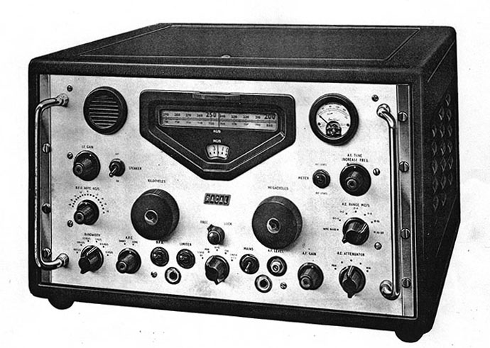
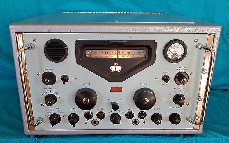
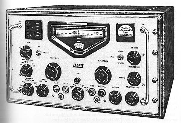
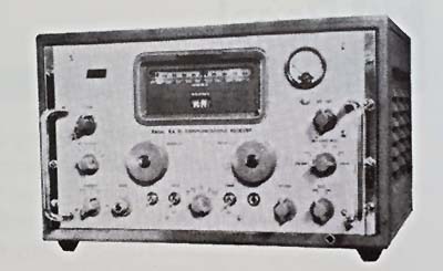
RA-17 Mark I - The initial version of the RA-17 was only built for about one year. This earliest version is sometimes called the Mark I, although that was never an official designation. Shown below-right is the advertising artwork depicting the initial appearance of the RA-17. The introduction artwork is a very accurate depiction of the RA-17 Mark I as will be noted by observing the photograph of the RA-17 Mark I owned by Anthony Howard (who supplied the photograph shown below-left.) The knobs, the meter, the toggle switches and the speaker bezel appear to be the most obvious differences between the earliest receivers and those produced somewhat later. |
|
|
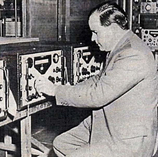
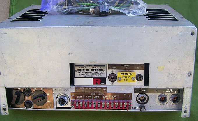
RA-17 Mark II - These receivers had several upgrades. Most Mark II versions will have the single pentode RF amplifier and the RF coils in the preselector are an "auto transformer" in construction with no separate primary winding. This style of coil was later changed to a true RF transformer type of construction using a primary and secondary winding. The Mark II BFO NOTE KC/S control only spans +/- 3kc. This function was later increased to +/-8kc on Mark III receivers. The IF BANDWIDTH selections are 8kc, 3kc, 1.2kc, 750c/s, 350c/s and 100c/s while on the later Mark III, the selections are 13kc, 6kc, 3kc, 1.2kc, 300c/s and 100c/s. The receiver's front-end gain control was only marked "IF GAIN" not "RF/IF GAIN" as found on the later receivers. The meters may be Ernest Turner types or some receivers have a meter with "TRA" on the scale. Many of the serial number tags are marked "RECEIVER MARK II" but some aren't. Knob styles were changed but probably during the Mark I production. Probably the same for the square speaker bezel and the square flange meter. Note the photograph of Dr. Wadley tuning a RA-17 receiver shown further up this page. Note that these receivers have odd tuning knobs (with skirts) installed but otherwise appear the receivers have the later RA-17 front panel appearance (that is, not the Mark I appearance.) These receivers could be very early Mark II production. RA-17 Mark II - UK Version - Below are two excellent photographs of the standard RA-17 Mark II. The photos are from "Radiosurplus Elettronica srl" - a military radio surplus dealer in Italy. This early version of the RA-17 is serial number N1018. The meter has the logo "TRA" on the scale but is a 0-200uA with 10mw level marked in red. The front panel photograph interestingly shows a rather large set of clear plexiglass "scuff protectors." The rear chassis photograph shows the AC primary voltage selector switches on the left side of the chassis. This photo also shows the British coaxial connectors quite well. The special connector for the AC power cable (which is in the plastic bag on top of the receiver) is a three-pin receptacle with a threaded collar to retain it securely. |
|
|
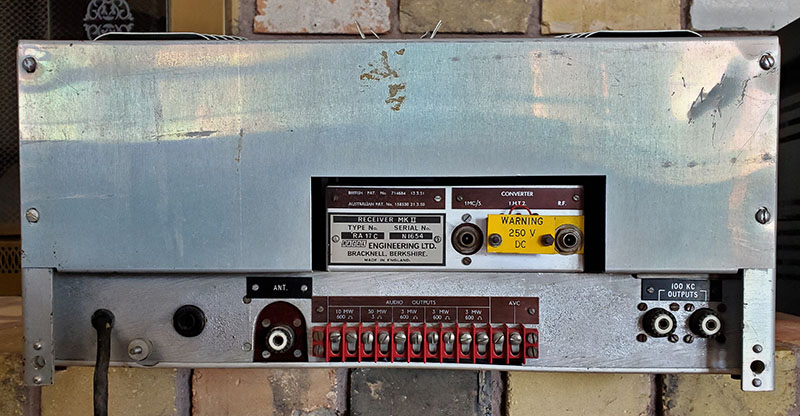
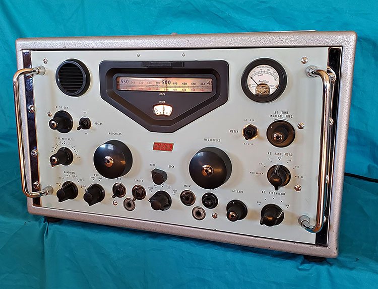
RA-17C Mark II - North American Version SN: N1654 The use of "C" as a suffix generally indicated the receiver was built in the UK for North American users, which normally meant it was for the USA (but sometimes indicated NATO.) The "C" suffix numbers start with "no suffix number" and go up to at least suffix number 26. It's probable that from suffix number 12 on, the receivers are Mark III versions. Shown in the photos to the left and below is a very early RA-17C receiver with no suffix number, actually identified as "RECEIVER MARK II" on its serial number tag with the serial number of N1654. Date-codes on the receiver components are from June 1959. Obvious are the different style pointer knobs used on this model. These knobs are somewhat similar to the standard RA-17 pointer knobs but without the grip fluting and without the skirt. These are original Eddystone 4669P knobs and seem to only have been installed on the early RA-17C receivers. Visible is the Ernest Turner W909 meter with the S-meter scale in green and, of course, the three position rotary switch for MONITOR function to allow RF LEVEL (nomenclature worn off,) S-METER and AF LEVEL. The cinch plug under the meter is access to the S-meter adjustment pot and this adjustment only affects the S-meter calibration. Note that the AC ON-OFF toggle switch is marked "POWER" and not "MAINS" - all receivers destined for the US market had this nomenclature change. The philip's head screws that mount the front panel seem to be original. They are 10-32 screws and all eight are identical with the same type of age-related surface oxidation. Also, the Limiter switch has been replaced at some time in the past (switch date-coded 1962.) |
|
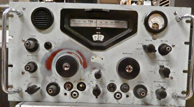
Unknown RA-17C The photo to the right shows another RA17C Mark II that happened to be for sale at Fair Radio Sales, formerly one of the largest surplus electronics dealers in the USA, located in Lima, Ohio, now out of business. Despite it's rather poor condition, it does show that these early "C" version receivers were supplied with Eddystone 4669P pointer knobs. Note that the knobs on this receiver are exactly the same type as those shown on SN: N1654. Though difficult to see, the meter is an Ernest Turner W909 with the S-meter scale. This photo was on the Fair Radio Sales website and this receiver did sell around February 2020. No serial number was supplied in the description. |
|
RA-17L Mark III |
The RA-17 Series receivers comprise many
slightly different versions, in fact, there were over 40 different
versions. Almost all RA-17 receivers will have a suffix that
further identifies what particular version the receiver was built
to. The version differences depended upon the end-user's
specific requirements. Versions from D up to K are usually Mark
II receivers but it depends on when the particular receiver was
built. The RA-17L was also known as the Mark III
and it had some significant upgrades built into the receiver. The RA-17L
became the basic UK version of the receiver. The Mark III changed the RF amplifier from a single pentode tube (CV3998) to a cascade connected dual triode tube (CV5531.) Also upgraded was the A-E preselector coils changing from resonated single coil assemblies to tuned RF transformers. This improved the Q of the preselector for better selectivity. The IF bandwidths were changed as follows; 8kc increased to 13kc, 3kc increased to 6kc, 1.2kc increased to 3kc, 750c/s increased to 1.2kc, 350c/s changed to 300c/s and 100c/s remained 100c/s. These bandwidths provided a wider response for voice transmissions such as shortwave broadcasts while the CW and data mode bandwidths remained essentially the same. The BFO range was increased from +/- 3kc to +/- 8kc and a vernier dial added to the BFO control to ease tuning due to its wide range of adjustability. V-24 was a wire-end vacuum tube diode that was only used in the earliest versions of the RA-17 and was replaced with a solid-state diode in the Mark II and Mark III. There are five audio outputs available on the rear chassis terminal strip. Three are 600Z ohm windings from the audio output transformer. The panel mounted monitor speaker runs off of the 3Z ohm winding of this same transformer. When the monitor speaker is switched off a 10 ohm load resistor is connected to the winding. The 3Z ohm winding also has a output connection to the rear terminal strip. The audio level of these four outputs is controlled by the AF GAIN. The remaining 600Z ohm output is controlled by the AF LEVEL control on the front panel and this output has its own separate audio transformer. This same terminal strip also has an AVC connection for running multiple receivers in diversity. Also accessed at the rear chassis is the RF and 1MC coaxial connectors and the HT1, HT2, AVC terminal connections for the LF Converter. If the LF Converter isn't used, then the HT1 and HT2 terminals must have a jumper installed to complete the +250vdc circuit in the receiver. Other rear connections are the dual 100kc IF outputs, the AE (antenna-earth) coaxial connector and the AC power cable connector. The primary taps on the power transformer are brought out to two switches that allow setting the proper AC input voltage level for the receiver depending on what is the local line voltage. Other minor Mark III changes were to the Stand By function with a 9K 10W load was added to the B+ when the receiver was placed in Stand By (also on RA-17C versions except value changed to 10K 10W.) |
|
|
The AE TUNE preselector
has six tuning ranges and a variable frequency "tuner." This tuned RF input can be bypassed in the
"wideband" position which is then an untuned "wideband" fixed 75Z ohm input. The
Antenna Tuning provides an increase in sensitivity by way of much better
signal transfer to the RF amplifier grid and also the Hi-Q allows for
better selectivity for the incoming signal which helps with
reducing interference from strong, near-frequency, near-field
signals. A four-step attenuator can be inserted into the
signal path to reduce the input level to the RF amplifier if
intensely strong signals are encountered.
The kilocycle tuning dial is a filmstrip type that is six feet long and spans 1000kc with a resolution of 1kc. When tuning the receiver, the dial index remains stationary while the numerical dial scale moves behind the index in a linear fashion. The megacycle dial is circular and is read thru the lower window of the dial escutcheon. The black kilocycle scale is used while tuning from 1-30mc while the red kilocycle scale is used when operating with the optional MW-LF-VLF converter (10kc to 980kc.) The tuning system is super-smooth and very light feeling. The film strip is easy to read to at least 1kc accuracy. The RA-17L uses triple-conversion and the drift reduction Wadley Loop provided solid stability. The normal Mark III bandwidth was selectable from 13kc down to 100hz in six positions although there were some versions the changed some of the selected bandwidths depending on the end user requirements. The RACAL RATT demodulators used the last IF as an input source. The last IF operates at 100kc and dual outputs were provided on the rear chassis. As with the Mark II, selectable fast and slow AVC and a Noise Limiter were provided on the Mark III. A standard diode detector was used and on very early Mark I receivers the BFO was lightly coupled (10pf capacitor) but by the Mark II the BFO coupling capacitor was increased to 47pf which provides sufficient injection to allow easy demodulation of SSB signals. The Mark III provided a toggle switch for the meter function with RF Level and AF Level as functions. The 10mw level is marked on the meter. This is measuring the 600Z audio output that has a separate audio output transformer and the front panel Audio Level control adjusts this output as needed. By the time the Mark III was introduced, Ernest Turner was supplying the meters and they were identified as Type W909. RA-17L Mark III receivers were generally equipped with military/commercial designated tubes. Ten CV138 tubes, one CV5531 tube, one CV2209 tube, two CV4012 tubes, two CV3998 tubes, four CV4009 tubes, two CV140 tubes and one CV1377 tube. There are some of these tubes that had RACAL approved substitutes. Also, the Pro-Electron (European designation) equivalents were usually listed for most tubes and most of the tubes could be substituted with US-type tubes. One exception is the CV2209/CV4064 or S6F33,...some lists show the 6AS6 as a substitute but this tube's screen grid and suppressor grid pin outs are reversed when compared to the correct tube. Also, "S" in S6F33 indicates the tube was a "special" 6F33. Whether a standard 6F33 will function correctly in the circuit is unknown (by me, anyway.) The RA-17L Mark III used 23 tubes but if one is using an earlier manual, V24 maybe be shown (CV469.) It was a wire pin diode tube used in the Mark I and possibly Mark II receivers. It was replaced with a solid-state diode probably by the Mark II but definitely by the Mark III production. The RA-17L chassis is shown to the left. See the RA-17C-12 (next section below) for chassis photo and detailed description. With the exception of the manufacturer of transformers used and the lack of the GZ34 rectifier tube, the chassis are nearly identical. |
The RA-17 Series tunes from 1.0mc up to 30mc in
thirty, one megacycle wide tuning ranges. Tuning from .5mc to 1.0mc
is possible but with noticeably diminishing performance as the
frequency is tuned lower within that range. If reception below
1.0mc was necessary then the Low Frequency Converter had to be
used. The RA-137 and RA-237 models connected to the RF input and
1mc input located on the rear chassis and then connections to
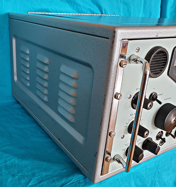
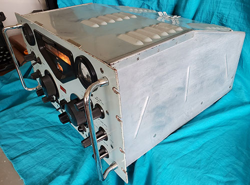
the receiver's +250vdc and AVC were necessary. The panels on the RA-17 receiver were originally Light Admiralty Gray (British Standard Specification 381C colour 697) which is sort of a light greenish-slightly bluish-grayish color (it was supposed to have been carefully designed to reduce operator fatigue.) Many of the panel colors that we encounter today have faded somewhat and could be a lighter shade than the original color was. It depends on the environment that the receiver operated in and, to a great extent, its physical condition. Many RA-17 receivers panels were equipped with panel "scuff protectors" that mounted against the front panel and behind the Kilocycle and Megacycle tuning knobs. These large, circular protectors were normally made from clear plexiglass and shielded the panel from "fat finger" syndrome. "Fat finger" wear was caused by the receiver operator rubbing their finger tips against the front panel by "over-gripping" the tuning knobs. The result, overtime, usually left the front panel paint worn off in a "ring" surrounding the knobs. The MC and KC tuning knobs along with the four or five "non-winged" smaller knobs have a collet-type of grip on the shaft. Knob removal requires using a hex wrench to loosen the chrome nut at the center of each knob. These collets shouldn't be over-tightened when reinstalling these knobs. Most of the RA-17 side panels have a slope beginning about halfway back and the top cover also slopes at the rear half of the receiver (see photo above and photo in RA-17C-12 section showing the top cover.) The front panel is steel and is the standard 10.5" x 19.0" but the receiver depth is 20.5" which is considerably deeper than any USA-made receivers. RACAL did supply a table cabinet for the receiver depending on the end-user's requirements. The top cover could be removed if the receiver was installed in a cabinet and was to be used in a warm environment. The standard RACAL cabinet was generally black wrinkle finish. Some later receivers, depending on the particular end-user, were supplied cabinets with other paint colors used. The RACAL cabinet shown is an original silver hammertone finish example that was used by the British Military. The RACAL table cabinets are steel construction and each of the sides have a recessed area where the louvers are (see photo right.) There are rear mounted engagement pins that mate with holes in the lower part of the rear side panels of the receiver. This provides rear support for the receiver chassis. The cabinet uses a single D-zus screw to secure the lid. Cabinets will generally have a RACAL metal label mounted inside rear bottom. Four large rubber feet are bottom mounted although some military receivers had shock mounts and skids (usually required if the receiver was installed as equipment in a towable or mobile communications hut.) Normally, the installation of the receiver into the cabinet included two chrome-plated strips that mounted over the rack mounting notches and protected the front panel paint from "rack rash." The Racal cabinet weight is 30 pounds which when added to the 67 pounds that the RA-17 weighs pushes the total weight of a cabinet-mounted receiver to nearly 100 pounds. |
|
RA-17C-12 Mark III |
The "C- Series" were the North American versions of the RA-17 built in
England but specifically for export, usually to the USA. There were over 20 different versions of
the C-Series of RA-17 receivers. Most of the different versions were for
specific uses, such as Broadcast monitoring where the BFO circuit was
eliminated and different IF bandwidths used or changes to allow
operation with specific models of Racal accessories. Generally,
the earliest C-versions are Mark II receivers. The RA-17C-12
appears to be the first Mark III version produced for North
America/USA. Some USA C-12 versions, if
supplied to the US military, were also
identified as AN/URR-501A if using the US Army-Navy designation. Most C-Series hardware is UNF
for USA compatibility. All of the tubes are USA types but two were
eliminated, the GZ-34 rectifier tube (by C-3) and V-24 were replaced with
solid-state substitutes. Two exceptions are the RA-17C first few
versions used a 5V4 tube rectifier and V-24 appears to have been
changed to SS very early in all of the RA-17 production. Other minor C-12 Series changes were to the 3.0Z ohm 50mw audio output that was increased to 1 watt. Also, a 10K 10W load was added to the B+ when the receiver was placed in Stand By (9K 10W on RA-17L versions) and standard UHF and BNC connectors were used for rear-chassis connection auxiliary inputs or outputs (for accessory devices.) The Antenna-RF preselector (panel ID: ANT TUNE on the C-series, AE TUNE on UK versions) is the same elaborate antenna tuning network that essentially provides a precisely tuned, Hi-Q output that feeds the RF amplifier grid. The preselector has six tuning ranges and a variable frequency "tuner." This tuned RF input can be bypassed in the "wideband" position which is then an untuned "wideband" fixed 75Z ohm input. The Antenna Tuning provides an increase in sensitivity by way of much better signal transfer to the RF amplifier grid and also the Hi-Q allows for better selectivity for the incoming signal which helps with reducing interference from strong, near-frequency, near-field signals. The four-step attenuator remained unchanged and can be inserted into the signal path to reduce the input level to the RF amplifier if intensely strong signals are encountered. The RF amplifier was a standard pentode tube in early RA-17 receivers but the C-12 Series used a cascaded dual-triode tube 6ES8 (the RA-17L Mark III also had this change although the tube used was an ECC189 or CV5531.) |
RA-17C-12 SN: N4144 from 1961 |
photo above: Top
view of the RA-17C-12 chassis |
To readout the tuned frequency one has to
add the megacycle dial setting to the kilocycle dial reading. If
the megacycle dial is set to 14 and the kilocycle dial reads 200
then the tuned frequency is 14.200mc (as shown in the RA-17C-12
photo above.) A 100kc Calibration oscillator is provided to
assure frequency readout accuracy.
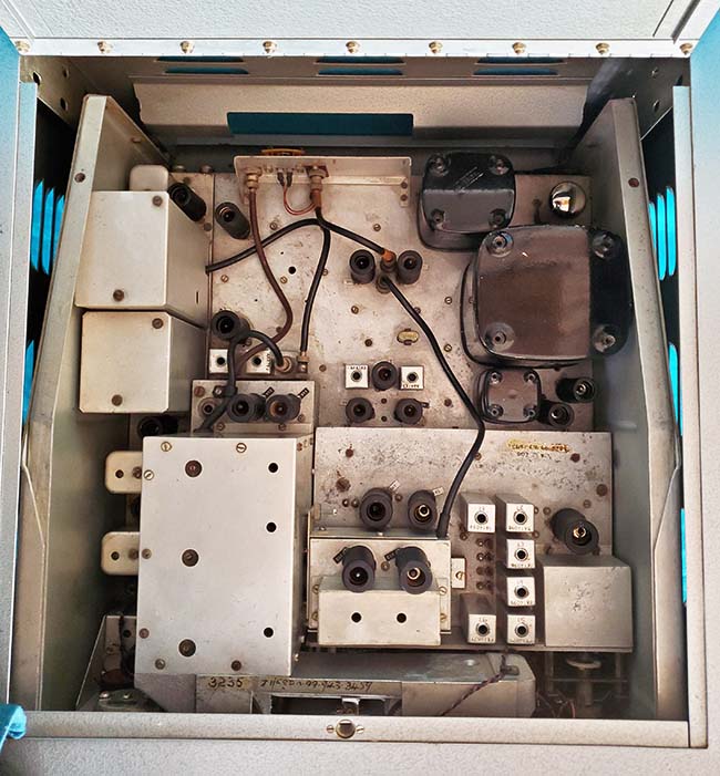
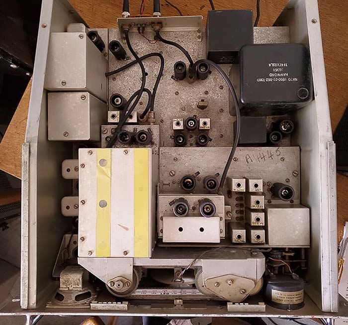
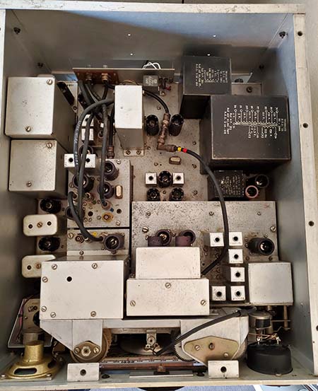
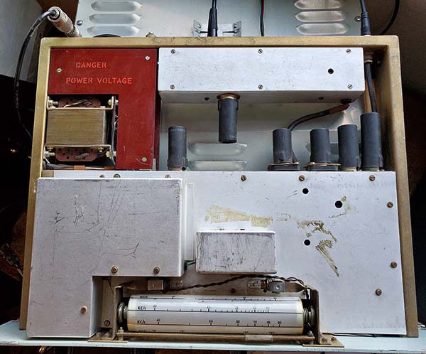
The use of triple-conversion and the drift reduction Wadley Loop provided solid stability. The normal C-12 Series bandwidth was selectable from 13kc down to 100hz in six positions but earlier versions will normally have 8kc as the widest bandwidth available. Last IF operates at 100kc with dual rear chassis outputs available. Selectable fast and slow AVC and a Noise Limiter were provided. A standard diode detector was used but (like the Mark III) the BFO is coupled via a 47pf capacitor which provides sufficient injection to allow easy demodulation of SSB signals. BFO is +/-8kc on the C-12 versions and usually +/-3kc on most earlier versions. The "C" versions had a three-position switch allowing RF level, S-meter and AF level functions. C-12 meters were generally supplied by Stark Electronic Instruments Ltd of Ajax, Canada but earlier C-versions use Ernest Turner meters. Several types of audio outputs are available at the rear connector terminals. C-12 series uses BNC connectors to provide 1MC output and RF input (for the LF converter and other compatible accessories) but the earlier versions use a UK-type connector. 100kc IF out is provided with SO-239 connectors. On all of the C-series, the AC power cable is permanently attached to the receiver chassis unlike the UK receivers that had an AC power cable that was removable and attached to receiver using a military-style connector. The GZ-34 rectifier tube was replaced with a 5Z4G tube in the earliest C-series receivers but by the C-3 version solid-state rectifiers were used reducing the tube count to 22 tubes. The RA-17C Series tunes from 1.0mc up to 30mc in 29, one megacycle wide tuning ranges. Tuning from .5mc to 1.0mc is possible but with noticeably diminishing performance as the frequency is tuned lower within that range. The RA-17C-12 (SN:N4144) shown in the photos has opaque black "scuff protectors" installed. Apparently, this type could be installed if the panel already had "wear-rings" since their installation hid any damage and prevented any further damage. Since these type of protectors aren't transparent the panel nomenclature that's covered is engraved into the black-on-white plastic material. It's quite possible that these opaque black "scuff protectors" were custom made for this particular receiver and really weren't "standard" accessory equipment since I've never seen any other "scuff protectors" like them. Top of the Chassis RA-17C-12 - In the photo view, top left are the Selectivity filters and in front of those two modules is the IF section of the receiver with the BFO in the very front (under the speaker.) Top center is the Harmonic Generator and the 1mc oscillator (note the 1mc crystal on chassis.) Below the 1mc crystal, the cluster of three tubes comprise the Harmonic Mixer and the 37.5mc amplifiers. The left module with the yellow tape is the KC-VFO and conversion mixers and the module just to the right is the calibration module and then the MC-VFO and conversion mixers with the RF amplifier tube to the far right. Front center is the film strip dial drive, speaker to the left and meter to the right. The power transformer and power supply components are located upper right in the photo. Audio transformer is in front of the power transformer. The RA-17L uses Gresham transformers while the RA-17C-12 uses Hammond transformers. |
|
|
RA-17 Versions |
RA-17 - Mark I - First version
was only built for one year. When compared to the Mark III
versions, the Mark I had different
selectivity positions, different antenna-preselection coils,
pentode RF amplifier tube, different meter. RA-17 - Mark II - Improvements to 100kc filtering, also minor improvements to appearance. Different knobs, different meter housing, different speaker bezel when compared to Mark I RA-17L - Mark III - New selectivity positions, double tuned antenna coils, dual triode RF amplifier tube, usually also referred to as the Mark III version. There are at least twelve different types of "L" versions. RA-17C Series - Primarily for North American market with US-type tubes, hardware, BNC connectors, many other minor differences. Over 20 numbered C-versions. Alternately identified as AN/URR-501A by the US military. The following is a detailed list of the many versions of the RA-17 that were produced. This list is from: "Keith's Vintage RACAL Enthusiast's Site" www.recelectronics.co.uk |
RA-17B ~ Only four selectable bandwidths on this version of the RA-17 RA-17C ~ Designation for the early versions built for North America-USA - used 5V4-G tube rectifier - SN: N1654 has date-coded components June 1959 RA-17C-2 ~ Canadian Army Model has modified BFO and MC drive, otherwise like RA-17C-3 RA-17C-3 ~ Standard North American-USA version with solid-state rectifiers and 75Z ohm wideband termination RA-17C-5 ~ Similar to C-3 except +/- 6kc BFO range RA-17C-6 ~ Similar to C-3 except with double-tuned circuits and AVC in the RF amplifier stage RA-17C-7 ~ Similar to C-6 except partially changed over to UNF screw threads RA-17C-8 ~ Similar to C-3 except with time delay compensation IF circuits RA-17C-9 ~ Similar to C-3 but changed for use with RA78B RA-17C-10 ~ Special build? - no details available RA-17C-11 ~ Special Order only RA-17C-3 with time delay compensated IF, Bandwidths 1.2, 3, 8kc and additional IF output with 5kc bandwidth RA-17C-12 ~ Standard North American-USA version of the RA-17 Mark III, UNF screw threads throughout, 1 watt AF output (3Z ohm) US Military designation AN/URR-501A - SN: N4144 has date-coded parts Oct 1960 RA-17C-13 ~ Special Order only C-12 but with pentode RF amplifier and dial brake on the MC control RA-17C-14 ~ Special Order only "Broadcast Version" of the C-12 with bandwidths of 1.2, 3, 5, 7, 9 and 13 kc RA-17C-15 ~ Special Order only C-12 modified for use with MA78B RA-17C-16 ~ C-12 modified for Dutch Army but no other details RA-17C-16/1 ~ Special version for the Netherlands but no other details RA-17C-17 ~ C-12 modified for use with MA257 RA-17C-18 ~ C-12 with time delay compensated IF, bandwidths of 1.2, 3, 6.5 and 13kc, additional IF output with 5-8kc bandwidth RA-17C-19 ~ C-12 modified for use with RA78D and RA66 RA-17C-25 ~ see RA-17L-5 RA-17C- 26 ~ C-12 modified for use with RA66 RA-17D ~ Early version for North America-USA with 13kc bandwidth replacing 3kc bandwidth RA-17E ~ RA-17 with 13kc bandwidth replacing 3kc bandwidth RA-17F/G ~ RA-17 Mark II with 6BA6 compensated IF section RA-17H ~ RA-17 with time compensated delay IF circuits RA-17J ~ RA-17 with double tuning in AVC and RF stages RA-17K ~ RA-17 Mark II modified for use with RA78 RA-17L ~ The standard British version of RA-17 Mark III RA-17L-2 ~ RA-17L with UG-style Antenna receptacle RA-17L-3 ~ RA-17L with Thorn Pigmy connector RA-17L-4 ~ RA-17L modified for use with MA1350A RA-17L-5 ~ RA-17L modified for use with MA1350A and RA66 (aka RA-17C-25) RA-17L-6 ~ RA-17L modified for use with RA66 with addition of MA251(RA-66 buffer module) RA-17N ~ Special version with 1.6mc IF stage and coupling facilities for use with MA143 RA-17P ~ RA-17L Broadcast version with special bandwidths of 1.2, 3, 5, 7, 9 and 13kc RA-17R ~ RA-17L modified for use in RA78 RA-17R-1 ~ RA-17R modified for use with RA66B by addition of MA251 supplementary to mods to operate in MA78 RA-17T ~ RA-17L with time delay compensated IF, no crystal filter, provision for video output using separate onboard amplifier* RA-17U ~ RA-17L modified for use with MA257 RA-17W ~ Same as RA-17L with IF bandwidths of .2/.5/1.2/2/4/13khz also AVC changes - for GCHQ* Notes: RA-78 was a frequency
measuring receiver with nixie tube digital frequency readout and
other auxiliary gear -
all equipment mounted in relay rack Other data from Rinus Jansen's "The Racal Handbook" * = corrections supplied by Neil Clyne |
RA-117 Series, RA-6117 |
|
The RA-117 antenna preselector circuit was slightly changed to provide a "wide band" selection that was an untuned hi-Z input or to "wide band 75" selection that was an untuned 75Z ohms input. The USA-built RA-6117 eliminated the 75Z ohm wide band position. There is a switch position for 75Z WB but it isn't wired and there's no panel nomenclature. The six-step frequency ranges remained unchanged and still allowed tuning for maximum response for the particular frequency and antenna in use. There was also the step-attenuator provided for coping with very strong signals but still being able to retain the tuned selectivity that the R.F. TUNE (was ANT TUNE on the RA-17) provides. The RF amplifier used a cascaded dual triode tube (6ES8.) The major changes in the RA-117 were to the conversion frequencies and building in more capabilities of the receiver to interface with other types of RACAL equipment.
photo left: RA-6117 SN: 193 - built in Silver Spring, Maryland, USA, ca: 1966 |
The Wadley Loop front-end was basically unchanged but the RA-117
did add an extra conversion-IF amplifier stage
after the 2-3mc IF bringing the total conversions to four. The four
conversions consisted of a tunable 40.65-39.35mc, a tunable 2-3mc, a fixed 1.6mc and
a fixed 100kc. The additional conversion used a slightly different type KC-VFO (tuned 3.6mc to
4.6mc rather than the 2.1mc to 3.1mc VFO of the RA-17.) The KC-VFO/Mixer operated into a fixed 1.6kc IF which was then converted (crystal oscillator/mixer) to a fixed 100kc IF. The 3.6-4.6mc KC-VFO also featured an external input and an external output to allow the RA-117 tuning to control (or be controlled) by other devices. The Racal RA-79G exciter when used with the RA-117 could be set up to allow the RA-117 KC-VFO to control the exciter's tuned frequency, allowing a "transceive" operation. VFO selector switch is on the RA-117 front panel next to the Kilocycle tuning knob. IF bandwidths from 13kc to 100hz, Fast and Slow AVC, three position switch allows the meter to act as an RF signal level, AF level or S-meter, standard envelop detector - no product detector are the features provided and all were basically the same as the RA-17C. Several BNC inputs/outputs are provided for External VFO, various Oscillator Outputs, 100kc IF Output along with terminals for several 600Z ohm outputs and a 1W 3.0Z ohm output. There were some versions produced that had modifications to the AVC usually consisting of longer delay times to allow better copy of RTTY signals (British - RATT signals.) A separate audio output (600Z ohm) with an Audio Level control on the front panel that has its own output transformer and operates separate from the standard receiver audio output. This output was for driving a data device, an audio input RTTY converter, for example. The small built-in speaker can be switched off if a larger speaker is desired (connecting to the 1W 3.0Z ohm output works best.) RA-117 receivers use 25 tubes. RA-117 Series tunes 1-30mc in 30 bands. Also, .5-1mc tuning with noticeably diminished performance as one tunes lower in frequency within this range. The UK-built RA-117 front panel was the standard Light Admiralty Grey. Apparently all USA-built versions were cream
color with USA-style knobs. Scuff protectors aren't usually found on
RA-117 receivers because the EXT/INT
VFO front panel switch location interferes with their proper positioning. Although
the RA-17 and RA-117 panels are standard 10.5" x 19.0" the
receiver's chassis is quite deep at 20.5" which, of course,
won't fit into any standard American cabinets. RACAL offered
table cabinets that
were specifically for the RA-17/RA-117 and these types of
cabinets only increase the
overall receiver foot-print an inch or two. Even at that, the
RA-17 and RA-117 are huge receivers that demand a lot of bench
space. Other after-market
general purpose cabinets that have the necessary depth are
usually very large, very heavy and really increase the overall receiver size
and weight
substantially. However, most receivers usually will have their
dust covers and, like the R-390A, look quite nice setting on a
table "sans cabinet" and in that configuration don't seem
to take up all that much bench space. Photo Right - RA-6117 paired with the W6MIT "Big Rig": The RA-6117 is now paired with the W6MIT homebrew transmitter, the Model 45098, aka "The Big Rig" - a 450 watt input AM transmitter that looks like a small AM-BC transmitter. W6MIT built this transmitter in 1998. It has a 4-250A PA modulated by a pair of 572B tubes. The RF exciter is out of a T-368. The Audio Driver is a Bogen CT-100C PA amplifier. 300 watts output power. Go to W6MIT Transmitters - Professionally Engineered Homebrew Rigs. Use Home/Index for navigation. |
|
RA-6117 Top of Chassis - Much of the component layout is very similar to the RA-17 receiver. Note the extra module located next to the Selectivity filters. This is the Crystal Oscillator and Mixer module for the 1.6mc to 100kc conversion used only in the RA-117 or RA-6117 receivers. Note in the MC-VFO that two of the tubes have been oriented to the horizontal position. Many more coaxial cables in the RA-117 to allow for the INT-EXT VFO connections and output connections for the dual 100kc IF outputs. At the rear-center of the chassis, note the small Potter-Brumfield relay. I added this relay to provide the remote standby function that wasn't originally installed on this particular version of the RA-6117 (RA-6117A-1.) NOTE: I later removed this relay mod because of its non-originality. No holes were drilled and no components removed or changed when installing this non-invasive change. However, I found its function to be unnecessary. The same remote standby function can be accomplished using the B+ terminals (as recommended in the RACAL RA-17L manual.) Also, note how the side panels and the rear panel comprise an almost complete enclosure. The top cover is flat with small perforations for venting heat. This is typical of the USA-built receivers. UK-built receivers used the standard RA-17 type of side and sloping top. 1966 date-coded parts in this RA-6117 receiver. |
RA-117 Versions |
RA-117A-1 ~ RA-117A modified to North American version
with US-style plugs and US-type tubes RA-117A-2 ~ RA-117A modified for use with MA282/RA66B RA-117B ~ not used RA-117C ~ Broadcast version with crystal filter bandwidths removed (.1 and .3kc) RA-117C-1 ~ RA-117 modified for use with RA220B RA-117C-2 ~ RA-117 modified for use with RA133A RA-117D ~ Special for RA167. Replaced RA273 RA-117E ~ Royal Navy Version for RA220 - may have had a solid state fast-attack/slow-recovery AGC circuit installed RA-117F ~ Swedish Version of RA-117A RA-117Q ~ Double tuned RF input with 60kc IF bandwidth. North American version RA-117Q-2 ~ British version of RA-117Q RA-117R ~ RA-117Q but with 100kc IF centered on 100kc RA-117S ~ Special for GCHQ Tewkesbury ref TX RA-6117 ~ RA-117 Version built in Silver Spring, MD, USA, built with US components - SN: 193 date-codes from 1966 RA-6117A ~ Same as RA-6117, built in Silver Spring, MD RA-6117A-1 ~ RA-6117 with 100kc to 25kc IF conversion module mounted on outside of the rear panel of receiver Notes:
MA282 was a frequency changing coupler so the RA66
panadaptor would work with the RA-117 |
RACAL's Ham Receiver? |
Racal Communications, Inc., the USA-based company located in
Silver Spring, Maryland (from 1965 to '71,...Rockville, MD '72
to '97) built and offered a "ham receiver"
version of the RA-17,...the RA-71. The receiver was based on the
RA-17 and constructed in a similar fashion, Wadley Loop, cast aluminum
chassis, film-strip dial,...all of the familiar Racal features.
Tuning was from 500kc up to 30mc and used the same MC Tuning and
KC Tuning of the RA-17. Slight changes were made by adding a
Product Detector in the SSB/CW position and a tunable Notch
Filter. Also, the dial escutcheon was changed to a rectangular
set-up and the built-in monitoring speaker eliminated. Audio
output impedance or power is not specified but does indicate a
6AK6 AF Output tube. The knobs used were slightly different from
the standard RA-17 style. The RA-71 was built from 1965 thru
1966.
So,...why don't we see very many RA-71 receivers come up for
sale nowadays? The original advertised selling price was $1200! photo right: RACAL RA-71 |
|
RA-17 and RA-117 Setup and Operation |
Setting the
Power Transformer Primary Voltage on C-Series (USA) Receivers
- All of the RA-17C-Series receivers had their power
transformer primary taps set to 115vac from the factory. 115vac was standard line voltage in the
USA during 1960s. Today, most line voltages are somewhat higher,
usually running between 120vac and 125vac. Changing the power transformer primary
voltage input on USA versions will require moving one or two
soldered wire connections to other terminals.
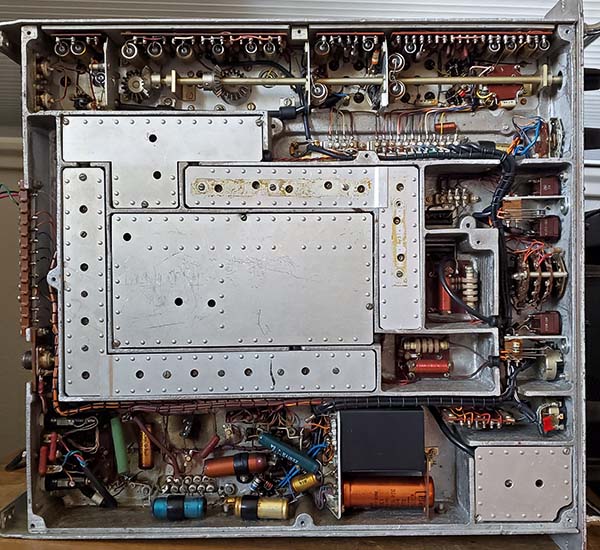
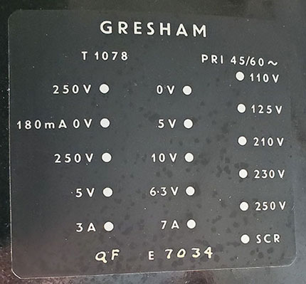
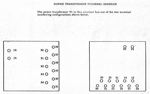
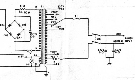
The early RA-17C receivers used a Gresham T-1078 power transformer (UK RA-17L also used the T-1078.) The pin outs are printed on the label on the side of the transformer. The label is shown below because the Gresham pin-outs are somewhat different than later transformers. Later receivers that used solid state rectifiers have the Hammond power transformers that didn't have a 5vac winding or the HV CT. There isn't any terminal to winding information printed on these transformers. Only the terminal numbers are shown on the transformer. The terminal to winding cross-reference is not shown anywhere in the RA-17 UK manual and not even in the RA-17C-12 UK-USA manual. The probable reason is that the standard RA-17 British receivers had two voltage selector switches on the rear chassis for setting the primary voltage, essentially what's shown on the schematics. But, USA version receivers will have soldered wire connections to the power transformer terminals for setting primary voltage requiring access underneath the chassis. As mentioned, the terminals are numbered on the transformer but those numbers and their relationship to the primary winding aren't shown on the schematic. I'm not sure how the writers of the RA-17C Series manuals expected the USA users to set the primary voltage other than measuring the DC resistance of the windings and figuring out what went where. Fortunately, the RA-6117 manual has a power transformer drawing and the numbers are shown on the RA-6117 schematic. The later C-Series used a Hammond transformer. The USA-built RA-6117 receivers did have a slightly different power transformer (BTC Co.) but luckily both transformers are shown in the drawings. The terminal drawing, schematic and listing are shown below. The actual relationship of the terminal numbers to the primary winding is the same for both transformer types. Only the physical location of the terminals is different. Also note that in reference to the Gresham T-1078, if the 5vac winding terminals and the HV CT were eliminated, then the remaining terminals to windings layout is the same as the Hammond transformer. My line voltage runs 122vac so I've set my receivers and accessories to the 120vac setting. This requires soldering one wire to 125vac and soldering the other wire to -5vac resulting in 120vac input. With the terminals provided it's possible to set the primary voltage from a low of 100vac (110vac minus 10vac) up to 125vac (125vac minus 0vac) or 200vac (210 - 10) to 250vac (250 - 0.) |
Terminals Connections to Windings Cross-Reference
Terminal 20 - 0vac Primary Adjust - subtracts 0
from other Pri Term selected Terminal 23 - 6.3vac - connected to T1 shield
(Terminal 31) and to chassis Terminal 26 - 110vac Primary Terminal connections are the same for either TF4TX03LA or TF1RX03YY, only the physical location of the terminals on either transformer are different. |
Gresham T-1078 Transformer Label |
RA-6117 uses a BTC CO. power transformer identified as TF1RX03YY/BX-3944 with terminals as shown in the drawing on the right |
The only schematic showing the terminal numbers as referenced to the actual windings of the transformer is in the RA-6117 manual. Shown above is a portion of the schematic showing the terminal numbers. The terminal number to transformer winding connections are the same for both types of transformers. |
Using HT-1 and HT-2 as Remote Standby - While the RA-117 receiver had an easily accessible remote standby relay to disable the receiver during transmit, the RA-17 only had a front panel standby and didn't supply any specific method to remotely disable the receiver. But, the RA-17L manual does mention that breaking the connection between HT-1 and HT-2 can provide a form of receiver muting when an associated transmitter is keyed. This can only be done if the Low Frequency Converter is not used since its B+ functions use the same HT-1 and HT-2 connection terminals. |
Using Date Codes to Estimate Receiver Build Date - Some components used in the RACAL receivers will have date codes on them for that component's date of manufacture. There are two that are easily found. The best date code was hand-written on the Gresham power transformer when it was built. Unfortunately, it is a true "code" and has to be interpreted since the code consists of two letters. The first letter is the year and the second letter is the month. Note the photograph in the power transformer section above, in particular, the Gresham T-1078 label. Note the handwritten letters "QF." This code is Q=1959 and F=June. Here's the breakdown of the letter code used. |
Q = 1959
A = January R = 1960 B = February S = 1961 C = March T = 1962 D = April U = 1963 E = May V = 1964 F = June W = 1965 G = July X = 1966 H = August Y = 1967 J = September (letter "I" wasn't used) Z = 1968 K = October L = November M = December |
The other date code is on the Plessey electrolytic
filter capacitor. This date code is a month and year.
The month is a three letter abbreviation, e.g. OCT, and
the year is just two digits, e.g. 60. Usually the
mounting of the filter capacitor makes seeing this date
code a little difficult. I've had to use a small dental
mirror to find the code but once you've spotted it,
reading it is easy.
Caveat on Date Codes - On the Plessey capacitor and the Gresham transformer,...these components were dated at their manufacture. Then they were shipped to RACAL, went into RACAL stock, then they had to be drawn out of stock to assemble a receiver. It would be expected that any date code will be a date somewhat earlier than the actual receiver built date. As an example, the RA-17C Mark II receiver has the Gresham power transformer that's dated "QF" or June 1959. However, the Plessey filter cap has the date code of "MAY 59" - at least a month earlier. Probably the earliest this receiver would have been built would be in August of 1959 (and that's just a guess.) Still, date codes can get you fairly close to a build date estimate. |
Meter Details for the RA-17
and RA-(6)117
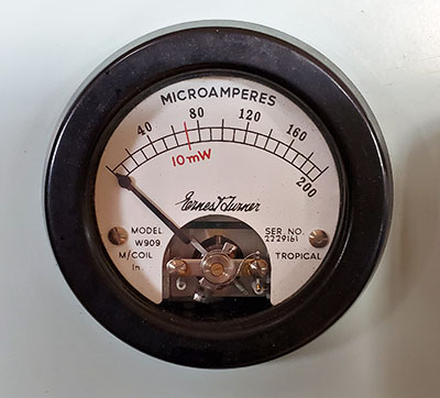
- RA-17 receivers built for the UK were equipped with a 200uA fs meter with
a single scale to indicate RF and AF levels. Some early RA-17
receivers were equipped with a meter that has a "TRA" logo shown
on the scale as the manufacturer. Sometime during Mark II
production the meters were being supplied by Ernest Turner and
identified as a Model W909. Turner meters have a red index line
indicating the 10mw AF level into 600Z on the 200uA scale.
Ernest Turner meters are considered somewhat delicate by
enthusiasts and defective ones were sometimes replaced with
other types of meters. North American RA-17C versions added a
three-position rotary "meter" switch and an S-meter
function-scale (in green) was added to the meter. Ernest Turner supplied this "S-meter" style of meter on
early North American versions but the meter itself is still
identified as Model W909. By the North American C-12 version, the meter
was supplied by
Stark Electronic Instruments Ltd (located in Ajax, Canada) and identified as Model 605HSR.
The UK RA-17L Mark III versions still used Turner meters with
just the 200uA fs with 10mw marked.
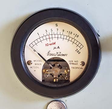
If the S-meter position is used it will show a relative indication of signal strength but the readings will depend on several factors including antenna type, the received frequency, the setting of the RF Attenuator or the tuning of the preselector. The adjustment pot behind the cinch-plug (just below the meter) is for the S-meter function only. Note that the scales are slightly different between the Turner meter and the Stark meter. The Turner shows a little over S-7 at 100uA while the Stark shows a little less than S-5 at 100uA. The Turner meter shown is on a RA-17C Mark II while the Stark meter shown is on a RA-17C-12 Mark III. Stark meters were also used on the UK-built RA-117 receivers. The AF meter indication works only on the 600Z ohm 3mw line which has its own individual output transformer and is controlled by the Audio Level control located next to the AF Gain control on the front panel. If you have the Audio Level control set to minimum you will not see any indication on the meter. If you want to see an audio level then you have to install a load resistor of approximately 680 ohm 1/2W load resistor to the audio line terminals on the rear of the chassis. The other unused audio outputs should also probably have similar load resistors installed. With the meter switch in the RF Level position, if the BFO is turned on, it will show a constant level on the meter. RF Level only shows received signal carrier levels in the AM mode. In CW or SSB, the meter will show the BFO level plus the level that the signal is above the BFO level. Since CW and SSB are not 100% duty cycle modes the meter reading will follow voice or CW peaks that are above the BFO level. The meter used in the RA-6117 is a Honeywell Model HS2Z. It has the same type of scale as the Stark Electronics Instruments 605HSR meter but the housing is somewhat different having a convex glass cover. Four examples of meters used are shown below |
|
|
|
|
Reworking Overview
- The RA-17 or RA-117 are not easy receivers to work on. The
modular construction allows removing individual circuits from
the chassis but almost all modules are a combination of hard-wiring
interconnections to other modules or to component boards along with
some
coaxial cable-BNC interconnections. Module removal will many
times require partial receiver disassembly and always some wire
unsoldering. With good documentation, the process isn't too
difficult but be prepared - none of the modules just "plug-in."
Luckily, most manuals are available online. The RA-17 and RA-117
are comparable to the R-390A or the 51J Series for level of circuit complexity. The components used in RACAL's UK-built receivers are average, consumer-grade parts. Some UK rebuilders actually even consider the British components to be "below average" in quality. Capacitors will probably require replacement since they are now at the half-century mark for age. Resistors should be checked for value-drift. On the other hand, the USA-built receivers seem to have top-quality US manufactured components installed (Sprague capacitors and AB resistors.) However, that's no guarantee that these components will have survived with no degradation over the past fifty years. Many of the component problems can be caused by a poor storage environment that has temperature cycling with huge excursions along with high humidity causing corrosion and moisture ingression. Storage in sheds introduces the possibility of rodent infestation. If the receiver under inspection has signs of having been stored in these worst of conditions expect a multitude of problems to be encountered during the rebuild. There is an old adage about "Racal solder joints" that does seem to be a sort of common problem. These are "cold solder joints" (Brits call them "dry solder joints") that just need to have the solder "re-flowed" to correct. My RA-6117 had a cold solder joint in the 1.6mc Mixer/Oscillator module that caused intermittent operation. As with any "half century old" electronics gear, you will find problems - even on functional units. Besides electronic problems expect mechanical wear, cosmetic problems and corrosion to be encountered. After all, most of these receivers were used by either the military or commercial users, so end-user abuse was fairly common. A source of instabilities and birdies can be poor contact on the shielding under the chassis. There are seven smaller shields that fit into place under the chassis. Six are providing complete shielding of the Wadley Loop circuitry and one shield is over the RF attenuator. These must be present and must be making good contact with the chassis to prevent feedback and oscillations from occurring. Other instabilities can be caused by the components is the KC VFO where the underside is completely sealed with no way to dissipate heat build-up. The heat, especially in military 24-7 operations, seems to have sometimes caused component drift. Unfortunately, getting into the KC VFO requires complete disassembly of the receiver. Alignments need to follow the instructions in the manual as sometimes special equipment is needed. Some of the filters in the MC-VFO Mixer and the 1mc Harmonic Generator might need to be sweep aligned if they've been carelessly tampered with. Check the instructions before "diving in." Alignment adjustments are located almost everywhere on the chassis. Expect to have to receiver on its side for much of the alignment, however the IF bandwidth crystal filter adjustments are accessed on the side of the receiver, requiring the receiver to be "rightside-up." Like any complex receiver, the first one worked on is your learning experience and any that follow become more familiar and easier to get through. If you've successfully reworked R-390A or 51J receivers, then you'll know what to expect in a RA-17 or RA-117 receiver. Paint Touch-up - Matching front panel paint color - I had some minor chips and scratches on the RA-17L that would look better if touched-up. I used Testor's Model Lacquer Paint. It's the paint found in hobby stores in the very, very small glass jars. I used Flat Green - it's a light olive green (~1 part) mixed with Gloss White (~10 parts) and a just very, very small "touch" of Gloss Dark Blue and an even smaller "touch" of Flat Black. The gloss mixed with flat will dull down the gloss to match the panel better. Do your matching in as much natural light as possible. I mix by eye to get the general tint and then get a close match by actually touching up an edge of the panel. Wipe off your mixes until you get it close. Remember, the paint will dry slightly darker so have your "wet" match just a slight shade lighter. Wait for the paint to dry to judge how close of a match you got. If it's good, then proceed with touching up the panel. This procedure is just for small nicks and chips, not to cover up major problem areas. Cleaning Knobs with Collett Grips - If you plan on doing a soak cleaning of these types of knobs be sure to disassemble the collett grip from each knob. There is a spacer in the smaller knobs that is made of garolite which is a fiber board type of material that might be damaged by soaking. The larger tuning knobs have a plastic spacer. The assembly consists of a brass collett, then a spacer and then the tightening nut. When the knobs are apart then the collett can be cleaned as they usually are somewhat oxidized even though they are brass. Use a brass "tooth brush" to clean off the oxidation. After the knob body is clean and dry (after its soak) then reassemble the collett grip in each knob. RF Amplifier Tube CV5531/ECC189/6ES8 - This is the dual triode tube used in the Mark III versions of the RA-17. More than once I've heard about the failure to this tube happening more often than one would expect. The symptoms are weak signals. You can hear the stations a little but the CL meter doesn't move in RF and the Antenna Tune/Preselector won't peak the signal. I my case, the tube tested as triode g-7,p-6,c-8 tested as having a hard short. The second triode was okay. The tube was a Raytheon ECC189/6ES8. I replaced it with a NOS GE 6ES8. The new tube corrected the problem. I wouldn't have mentioned it but I've heard of this same problem from other RACAL enthusiasts. |
|
|
RA-1217, RA-6217 Receivers |
|
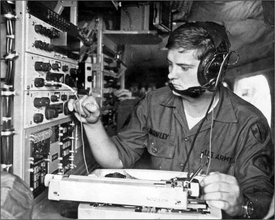
By the late-sixties, the RA-17 and RA-117 were competing with many solid-state communication receivers built by other companies. In 1967, the all solid-state RA1217 (UK) and RA-6217 (North America) were introduced. The same concept of using triple conversion with a Wadley Loop became the basis for these new receivers. Mechanical digital readout and a tuned preselector, along with a very small, light-weight package were the main features of the RA-1217 and the RA-6217. These receivers were comprised of several plug-in modules fitted to a main frame chassis. As with earlier receivers, many Racal accessories were available for these receivers and there are many inputs and outputs on the rear panel to accommodate all of the optional equipment. The receiver operated on 115vac to a power supply module that then supplied the -16vdc to operate the circuits. At only three and a half inches in height, several receivers could be operated within a very small rack space. The RA-1217 and RA-6217 were produced up into the late-seventies.
photo left: A US Army SSA Radio Operator using two
RACAL RA-6217E receivers and the matching panadaptor, the RA-366B
- Vietnam War Era.
Note that there is another RA-6217E dual receiver and panadaptor
setup
behind the foremost operator. This US Army photo is from
their website, army.mil. The caption reads "The Army
Signals Security
Agency provided direct support Signals Intelligence detachments
to tactical units throughout South Vietnam." |
Getting one RA-6217E Working - On the test bench, I checked over the mostly complete RA-6217E and, other than being filled with sand and tree leaves, it looked like it was in pretty good shape. A careful power-up had the receiver working,...sort of. Contact cleaning and manipulation of the controls got the receiver working fairly well, at least on AM, USB and CW. LSB and the tuned BFO were non-functional. The RF meter was pinned to the negative but worked in the Audio mode (these problems ended up being corrected with adjustments that were on the IF module and the meter driver board.) The audio was taken off of the Phone jack (600Z) and used to operate an eight inch 600Z loudspeaker. Audio was impressive. Luckily, the 75% complete, "parts set" receiver had the RF module shield so that was removed and installed on the RF module of the operational receiver. The mechanical digital readout on the working receiver was in really rough condition but the two "parts sets" had excellent digital readouts. Replacing the mechanical digital readout is no easy task but I removed the readout set from the "75% receiver" to formulate a removal procedure. It requires moderate disassembly of the receiver's front-end along with maintaining a mechanical alignment during the readout swap. Before starting, tune the receiver to 00-000 and slowly tune further negative in MC and KC until the mechanical stops are contacted. In my case, the MC stopped at -00 and the KC stopped at -938. When removing the readouts, the MC readout is one unit and the KC is another unit. They are removed individually. To access the MC/KC readout requires front panel removal. Then dismount the meter, the meter switch, both dial lamp mounts, the fine tuning pot, the VFO switch and the harness clamp. The MC rotary switch has to be dismounted and the cover removed off of the VFO. Access to and removal of the MC readout is now very easy. >>> |
I used binder head screws. These should be 4-40FH undercut screws. Will change soon |
|
>>> Not so though for the KC readout. The KC readout is mounted with
four screws, two screws are easy to access but the other two require a
low profile, offset blade screwdriver to remove. Once these two
difficult to remove screws are out then the KC readout can be
removed. Installation of the good condition readout set was essentially
the reverse of the removal procedure. The mechanical alignment of the
various gears has to be checked during reassembly because it is possible to have the mesh
too tight resulting in difficult tuning. When the mechanics are correct
the tuning is very light. If accurate mechanical settings were
maintained during reassembly then the receiver should power-up and
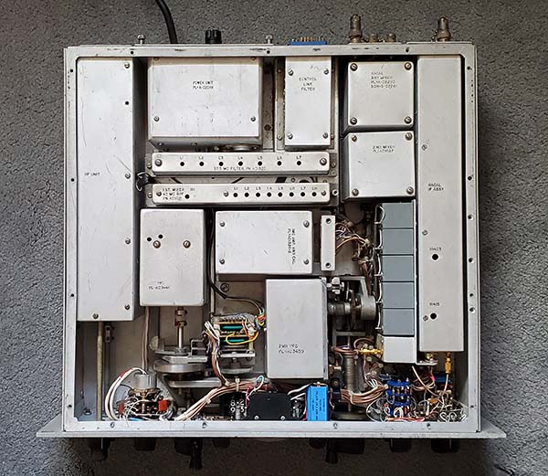
receive signals at the proper frequency readout (,...and it did.) Two problems remained,...LSB still didn't function (I'm suspecting the "soldered-in-place" crystal) but I can use the variable BFO to receive LSB, so that wasn't a crucial problem. Then there was the missing top cover. I made the top cover out of .060 aluminum. Luckily, there's no venting of any type - just a flat piece of metal. Once the aluminum piece was cut the mounting holes were measured, marked and drilled. Then the aluminum was sprayed with Easy Off Oven Cleaner (NaOH Sodium Hydroxide.) NaOH will produce a matte finish on the aluminum surface. Just spray on, let it set for a few minutes and then rinse with cold water. Don't rub, let it air dry or use a heat gun to dry. The finish will be flat or matte aluminum which is like the original. There's no need to coat the finish with any sort of "clear coat spray." The cover can be mounted as soon as it's dry - and it was. The 1 watt 15Z ohm audio output is accessed from the rear multi-pin connector/socket. Also, remote standby is on the same connector. I will have to make individual pin connections using push-on terminals. Photo left shows the top of the RA-6217E with the top cover removed. The left-most module is the RF module. Upper left next to the RF module is the Power Unit and next to the right is the Control Line Filter unit. The long narrow modules are VFO and Mixer filters. Below them and left is the 1st VFO (MC,) to the right-upper is the 1MC Osc and below it is the 2nd VFO (KC.) The long module to the right is the IF module. To its left upper are two Mixer modules. Though it's difficult to see, the chassis is a complete aluminum tub with welded corners and an almost complete bottom. There's a small access cover on the bottom side of the chassis. Most modules plug into sockets though most do have other wiring also. The front of the receiver has most of the components mounted to the chassis and the front panel then mounts to the front of the chassis. The meter mounts using its bezel through the front panel and secured at the backside of the front of the chassis which complicates front panel dismounting. |
Other Early Solid-State RACAL Receivers - The RA-217 was an all solid-state version of the RA-117. It featured a mechanical digital readout for KC tuning, Wadley Loop, product detector and crystal controlled, fixed USB and LSB BFOs. The RA-329B was a militarized RA-217 paired with a MA-323 FSK unit in one square packaged military case. The RA-1218 was essentially the RA-1217 with a Nixie-tube digital display built-in. The RA-1219 was the same as the RA-1218 but with a Wadley Loop control of the KC VFO. |
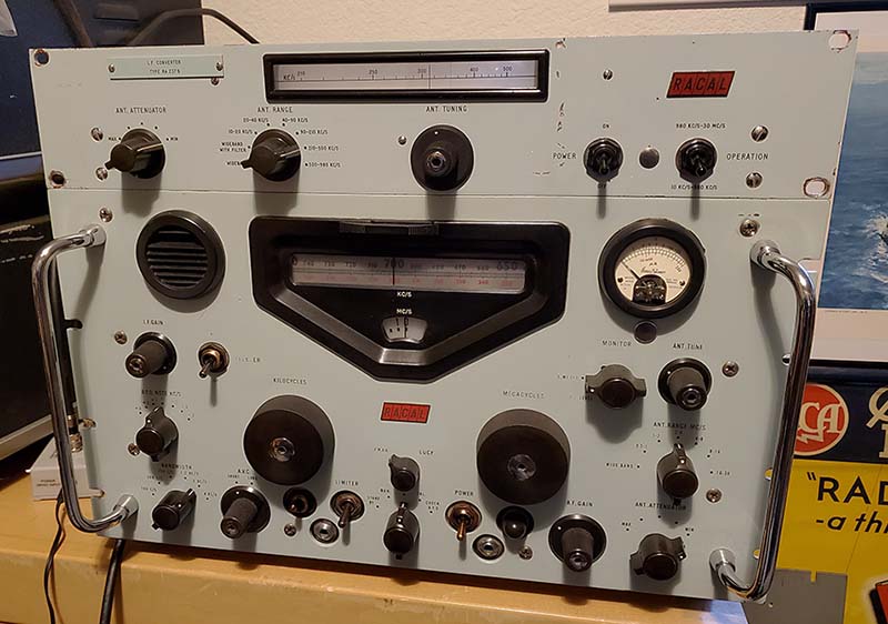
Using the Racal RA-237-B L.F. Converter with the RA-17C-12 Receiver on MW, LF & VLF |
|
>>> The RA-237-B up-converts the incoming RF signal into the 2-3mc range by mixing the 1mc Xtal Oscillator from the RA-17 with the incoming LF RF signal from the RA-237-B. The RF input is routed through a low pass filter system and the 1mc Xtal Oscillator is routed through a harmonic generator and a band pass filter. Both signals combine in the Mixer stage. The RA-237-B Mixer output is connected a cathode follower buffer and then to the RA-17's 2nd IF input (2-3mc.) From there the remaining RA-17 circuitry functions can be utilized. The RA-237-B provides a tuning range of 10kc up to 980kc. The RA-237-B has its own antenna and RF input preselector tuning system that is similar to the RA-17's. Wideband and Wideband with a 500kc low pass filter can be selected which bypasses the preselector. Using the preselector allows precise tuning of the incoming RF signal before its routed to the RF amplifier grid. The attenuator allows signal reduction if extremely strong adjacent frequency signals are present, such as on the AM BC band. The ANT. TUNING control tunes the RF signal input within each selected range and the approximate resonant frequency is readout on the illuminated slide rule dial. The drum dial rotates with each range selected and displays "band in use." The POWER ON toggle turns the tube filaments and dial lamps on only. The OPERATION toggle selects whether the LF converter controls RA-17 tuning or bypasses the converter allowing HF operation of the RA-17. >>> |
|
There are two coaxial cable interconnections to the RA-17, RF and 1mc and
then three wire connections, HT1, HT2 and AVC. HT1 and HT2
provide the +250vdc B+ voltage supplied from the RA-17 and is controlled with the
OPERATION switch. AVC allows the RA-17 AVC to control the
RA-237-B RF gain or manual gain can be selected if desired. The
LF antenna input is via a SO-239 connector. The converter has shielding to the various modules but full shielding of the chassis was not provided. Racal indicated that a special cabinet could be provided to house both a RA-17 and a RA-237-B (14" x 19" opening.)
RA-237-B SN: 371 - Servicing - This RA-237-B (SN:
371) was in very
good condition but it did need a little adjustment for good
performance. Of the six tubes, four had to be replaced. I ended
up replacing
both dial lamps because one was open. I replaced both lamps with #40
lamps, threaded base 6-8v 150mA. The ANT. TUNING readout was
mechanically off by about 30%. This required loosening the set
screws on the fiber tuning condenser drive gear, setting the
condenser to full mesh and then adjusting the readout to
slightly below the low end of the scale. This really isn't
"calibrating" or alignment, it just mechanically has the dial
readout agree with the mechanical position of the tuning
condenser. I also changed the AC input voltage primary on the
power transformer from 115vac to 120vac since our line voltage
here runs around 122vac. A few sheet metal dents and bends required minor body
work. Minor cleaning, mostly dust. The dial drum was sluggish in
changing position with band switching. A small drop of 10W
machine oil on the bearing got the dial drum rotating properly.
|
Testing
- I made up a three-wire harness for the HT1, HT2 and AVC
connections and found a couple of RG-58 test cables with BNC
connectors for the 1mc and RF connections. With the RA-17 and
the RA-237 powered, I first set the RA-17 to 530kc reading the
"red scale" on the dial. I then selected 500kc-980kc ANT RANGE
on the RA-237-B and tuned the ANT TUNING for maximum background
noise. The "nvroads" station was heard quite well (public service
type of BC.) I then tuned both units to 350kc and peaked the
RA-237-B. I heard the Canadian NDB NY 350kc in British Columbia
coming in and this was at about 3:30PM - the sun was still up! I
tuned WWVB 60kc and it was about 40db over S-9. USN VLF MSK
stations NLK 24.8kc and NAA 24.0kc were also received easily.
The operation is very easy with just tuning in signals on the
RA-17, reading the "red scale" using the Kilocycle tuner. The
Megacycle tuner is non-operational when the LF Converter is
being used so its setting isn't important. Peaking the RA-237-B
for best signal response will be necessary every few kilocycles
if weak signals are being searched for. For really weak signals,
the AVC should be turned off and the RF gain reduced along with
increasing the AF Gain. This will prevent the AVC from acting on
the noise and reducing the LF Converter and the RA-17 gain. Operation - With the RA-17 turned on and the RA-237-B power on, select "10kc to 980kc" with the OPERATION toggle switch. Using the Kilocycle tuning and observing the red scale on the RA-17 dial select a frequency, e.g. 350kc. On the RA-237-B, using the ANT RANGE switch, select 210kc to 500kc range. Using the RA-237-B ANT TUNING, adjust the dial to read approximately 350kc. As you near 350kc, the background noise in the RA-17 will increase and will peak somewhere near 350kc as read on the RA-237-B dial. As you search for a NDB station with the RA-17, peak the RA-237-B every 5kc or so. The converter's preselector circuit has a very high Q and the tuning is very sharp. The frequency is read directly on the red scale of the RA-17 and the approximate antenna peaking frequency is read on the RA-237-B dial. When searching for very weak signals, switch off the AVC and control the front end gain manually. This will prevent the noise level from controlling the AVC and reducing the front end gain. Manual control also is necessary during very noisy conditions. The Hi-Q ANT TUNING is narrow enough to reduce a lot of the LF reception noise in most cases and AVC can be used during good conditions and moderate signal levels. If you want to return to HF just switch the OPERATE toggle switch to 980kc to 30mc position and the RA-17 front end takes over and allows HF reception. Below are reception logs for the RA-17/RA-237-B combo from Nov 10 to Dec 12, 2019 (and reception updates out to Feb 20, 2020.) |
|
Reception Log for November 10, 2019 - 2150-2215hrs PST - Ant 135' "T" 1. YTL 328kc - Big Trout Lake, ON, CAN
|
|
UPDATE Nov 30, 2019
- I've started using a Pixel Technologies Shielded-Magnetic Loop
antenna with the Racal LF combo. So far, the performance of the
loop has allowed receiving NDBs east out to Quebec and west to
Hawaii. More details shown in the reception logs below. UPDATE Dec 6, 2019 - Below are reception logs using the RACAL RA17/RA237B with the Pixel Loop. The loop was indoors (second floor) and pointed NE most of the time. Conditions were great. 28 NDBs logged in a 25 minute session on Dec 5 and 27 NDBs logged on Dec 8. One newly heard station, YFM 332kc LaGrande, Quebec, #347 on the 5th of December. I also logged another newly heard station with the Pixel Loop/RACAL setup a few days earlier, PMV 329kc Plattsmouth, NE, #346. The numbers, e.g. #346, indicate total number of NDBs I've logged and this number increments up with each newly heard NDB. |
Reception Log for Dec 5, 2019, 1905hrs-1930hrs PST using Pixel Loop (*indicates not listed in previous logs) |
Reception Log for Dec 9, 2019, 1910hrs-1940hrs PST using Pixel Loop - 27 stations received (only stations not listed in previous logs are shown) |
1. YWB 389kc - West Bank, BC,CAN 2. PNA 392kc - Pinedale, WY 3. TW 389kc - Twin Falls, ID * 4. JW 388kc - Pigeon Lake, AB, CAN * 5. HAU 386kc - Helena, MT * 6. QV 385kc - Yorkton, SK, CAN * 7. PI 383kc - Tyhee, ID * 8. MR 385kc - Monterey, CA * 9. GC 380kc - Gillette, WY * 10. YE 382kc - Fort Nelson, BC, CAN * 11. EX 374kc - Kelowna, BC, CAN 12. YBV 370kc - Berens River AP, MB, CAN * 13. AA 365kc - Fargo, ND 14. SX 367kc - Cranbrook, BC, CAN |
15. ZP 368kc - Sandspit, Queen Charlott Is., BC,
CAN 16. DPY 365kc - Deer Park, WA 17. RPX 362kc - Roundup, MT 18. YQZ 359kc - Quesnel, BC, CAN 19. ODX 355kc - Ord, NE 20. IN 353kc - International Falls, MN 21. PG 353kc - Portage, MB, CAN * 22. NY 350kc - Enderby, BC, CAN 23. YXL 346kc - Sioux Lookout, ON, CAN 24. YZH 343kc - Slave Lake, AB, CAN 25. YY 340kc - Mont Joli, QC, CAN 26. RYN 338kc - Tuscon, AZ 27. ZU 338kc - Whitecourt, BC, CAN * 28. YFM 332kc - La Grande 4, QC, CAN * < newly heard station #347 |
1. ZZD 308kc - Edmonton IAP, AB, CAN 2. YIV 300kc - Island Lake, MB, CAN 3. Z1 305kc - Three Hills, AB, CAN 25W < newly heard station #348 4. UNT 312kc - Penticton, BC, CAN 5. YQF 320kc - Red Deer, AB, CAN 6. LGD 296kc - LaGrande, OR 25W 7. YER 334kc - Fort Severn, ON, CAN 195W < newly heard station #349 8. YLD 335kc - Chapleau, ON, CAN 9. MEF 356kc - Medford, OR |
Reception Log for Dec 10, 2019, 1905hrs-1935hrs PST using Pixel Loop - 22 stations received (only stations not listed in previous logs are shown) |
Reception Log for Dec 12, 2019, 2015hrs-2045hrs PST using Pixel Loop - 38 stations received (only stations not listed in previous logs are shown) |
1. YNE 207kc - Norway House, MB, CAN 1KW < newly heard station #350 2. IB 209kc - Atikokan, ON, CAN 3. RL 218kc - Red Lake, ON, CAN 4. YKA 223kc - Kamloops, BC, CAN 5. CG 227kc - Castlegar, BC, CAN 6. BR 233kc - Brandon, MB, CAN 7. XE 257kc - Saskatoon, SK, CAN 8. ZSJ 258kc - Sandy Lake, ON, CAN 9. GEY 275 - Greybull, WY 10. NM 278kc - Matagami, QC, CAN 11. CEP 278kc - Ruidoso, NM 12. QR 290kc - Regina IAP, SK, CAN |
1. VC 317kc - La Ronge, SK, CAN 2. YEK 329kc - Arviat, NU, CAN 500W < newly heard station #351 3. ZXE 356kc - Saskatoon, SK, CAN 4. HQG 365kc - Hugoton, KS 25W 5. YPL 382kc - Pickle Lake, ON, CAN 6. MM 388kc - Fort McMurray, AB, CAN 7. ML 392kc - Charlevoix, QC, CAN 8. DQ 394kc - Dawson Creek, BC, CAN
Total NDBs logged with RACAL setup - 102 (from Nov 10 to Dec 12) |
Medium Wave Performance -
The RA-17 and RA-237-B combination works amazing well for MW/LF
reception. The first four reception logs (shown above) list the NDB stations received with a
wire antenna which usually presents a fairly high noise level.
However, the very Hi-Q of the preselector in the RA-237-B helps
to reduce noise as does the double conversion scheme. The last
four logs are results using a Pixel Technologies Shielded-Magnetic Loop
antenna located indoors (2nd floor.) These last four logs show that
there is an definite advantage to using a loop antenna on MW, even in a
quite, rural area. NOTE:
The Pixel Loop doesn't provide stronger signals than the outdoor wire.
However, the signal to noise ratio is improved using the loop and this
usually provides the ability to copy weaker signals, that is, those
signals that are "right in" or "just slightly above" the now lower noise
level. None of the listening sessions were longer than 30 minutes and the total number of NDB stations tuned in was 102 NDBs, six of which were newly heard stations. The manual specs the sensitivity for the combo at 1uv for A1 and 3uv for A2 which is certainly believable, although noise levels in the MW, LF and VLF regions usually don't allow reception of signals at that level of sensitivity. Noise levels are lowest at night during the winter hours. That is one consideration when looking at these logs,...all reception was performed during the peak "low noise" time and best DX propagation time of the "longwave season" which is between October and February with the "peak time" being December and January. More reception reports in the updates below. UPDATE: Dec 11, 2019 - After using the RA-17 and RA-237-B combination for a little over one month and logging over 100 NDBs (with six newly heard stations,) I'd have to rate this setup as one of the best performers for MW and LF reception. Overall, the MW/LF reception is relatively quiet, even when using an large wire antenna. Since the received noise is low, very weak NDBs are easy to copy. The tuning dial is amazingly accurate, one of the best, usually holding 1kc accuracy (taking into account the BFO offset.) When the shielded-magnetic loop was added to the combo even better weak station copy was the result. The RA-17/RA-237-B's ability to extract very weak MCW signals out of a normally noisy reception environment is comparable to the Hammarlund SP-600VLF-31's similar ability. But, the low noise and dial accuracy advantages go to the RACAL set up.
UPDATE: Dec 20, 2019 - A listening session that began at
2155 hrs and lasted until 2225 hrs PST produced 37 stations logged. Both
POA 332kc and
LLD 353kc in Hawaii and
DDP 391kc in Puerto Rico were
easily copied. Three newly heard stations were logged,
ZPA 372kc Prince Albert,
SK #352, HY 374kc Hays, KS #353
and DL 379kc Duluth, MN
#354. 15 other NDBs were new for the RACAL setup bringing total logged
to 117 stations. Pixel Loop for antenna. Great conditions. |
Using Another RA-237-B with the RA-17C Mark II Receiver |
RA-237-B SN: 308 - Feb 2, 2022 - A second RA-237-B LF Converter has made it here. It was on eBay from a seller in NYC. It wasn't in the greatest condition and the seller didn't know its operational status, so the ending bid price was pretty low (for a RA-237-B anyway,...$116.) It's interesting that it's just 63 units earlier than my other LF Converter (sn: 371 versus sn: 308.) As received, not unexpectedly, it didn't function. Cosmetically, it wasn't too bad except that the dial window bezel was missing. The transparent plastic dial window was there but not the surrounding bezel. I doubted an original bezel would ever show up separated from another LF Converter so I carefully scraped the dried amber-colored glue off the panel and cleaned the area with Isopropyl Alcohol and 0000 steel wool (lightly) to even out the paint where the bezel had been mounted. The RA-237-B almost looked like it never had a bezel (those nicks around the dial opening were already there - probably from someone prying off the original bezel.) I plan on setting this LF Converter up with my RA-17C Mark II receiver but, for testing purposes, I have to use the RA-17C-12 because it has standard BNC connectors while the Mark II is an early version (1959) so it still has the "unobtainium" RACAL-type of coaxial connectors throughout. I tested all of the tubes in the LF converter and they all tested "as new." So, with the RA-237-B connected to the RA-17C-12, I connected up a 160ft end fed wire antenna to the LF Converter and powered up the combo. Both dial lamps were out. New #40s were installed and while I was at it, I changed the AC input from 115vac to 120vac (soldering wires to different taps on the power transformer.) When the RA-237-B was powered-up I had the receiver tuned to 630kc AM-BC and set up the LF converter to work the same frequency. I could hear KPLY and a little fine tuning got the signal where it could be heard at a low-to-medium audio level. Tried KKOH on 780kc with same results. RF LEVEL meter showed about 1/4 scale. Basically the RA-237-B was somewhat functional although nothing was heard on any other tuning ranges. >>> |
>>> Cosmetics - Feb 15, 2022 - I did
a "clean up" on the RA-237-B that involved dismounting the front panel.
It seems that the plastic window was originally glued to the back of the
panel and the glue had deteriorated and the window was now just held in
place by the dial pointer. I cleaned off the old dried glue from the
plastic window and from the back of the panel. I used epoxy to reglue
the window in place. The bottom of the window has to be very near to the
bottom panel opening. I mounted the window with about .125" overlap at
the bottom. This was actually excessive and the tuning dial assembly
couldn't be mounted to the back of the front panel without interference from the
plastic window. I had to trim about .060" of the plastic and slightly
enlarge the assembly mounting holes to get everything to mount
correctly. I remounted the front panel only to find out that the tuning
shaft gear now didn't mesh with the variable condenser shaft gear. The
correct order of assembly should be the front panel is mounted first,
then the dial drum drive mounted to the back of the panel and then its
position adjusted for proper gear mesh. Only then can the plastic window
can be glued to the back panel. There's only about .25" of clearance to
fit the window into place (which is why all plastic windows in RA-237Bs
have glue residue smeared around.) I had already cleaned the old epoxy
off of the window and back of the panel, so I carefully applied a small
amount of epoxy to just the two side edges and then, using tweezers to
hold the plastic window, I guided it in between the dial assembly and
the back of the front panel. I used two small cardboard wedges to hold
the window in place until the epoxy set up. What a pain,...but it worked
and looks fine. NOTE: I've ordered some .25" half-round plastic rod and will try to fabricate a decent-looking bezel. Update when it happens. NOTE #2: I checked SN:371 to see how that plastic window was installed and it is different. That window fits into the dial opening in the front panel and glues to the back of the bezel. I suspect that when the original bezel was removed on SN:308, so was the original plastic. The unglued plastic I found was probably an earlier repair attempt. With the plastic window recessed in the panel cut-out none of these interference problems would have resulted. I guess I should have checked SN:371 first! Luckily, correcting this is pretty easy. Making a Replacement Bezel - Mar 4, 2022 (out of chronological order, but fits in here for text order) - The .25" half-round plastic can be cut with a X-acto knife. I first made a tracing of the panel dial opening for a size reference. I marked off the 45º angles for the corners. I made these angled cuts slightly long so I could trim them to size. Once the four pieces were cut, I used blue masking tape as a "sticky" base to check the fit of the angles. The tape holds the pieces in position while each corner is trimmed to fit. Once the fit was correct, I checked to make sure the overall size was correct for the dial bezel opening, which it was. I used 5-minute epoxy to glue the corners. This was accomplished while leaving the blue masking tape as a "sticky" base to hold the four pieces together and with the proper "fit." Once the epoxy set-up, then the outside corners could be rounded using an emery board as a file. With the correct shape achieved, then the bezel had to be painted gloss black (the plastic half-rounds were white.) When the paint was dry, the bezel was glued in place using 5-minute epoxy. The end-results, while not exactly like an original, are excellent and it definitely improves the look of that "untrimmed" dial opening. |
Problem and Repair -
Feb 17, 2022
-
I moved the RA-17C-12 onto the workbench so I could start an alignment
on the RA-237-B. One of the first steps requires connecting the VTVM to
V3. When removing V3 from its socket, the movement caused the audio
output level in the RA-17C-12 to "skyrocket." It was intermittent
though, as soon as V3 was not pushed to one side, the audio level
dropped back to where it had been. I removed the bottom cover and a
quick visual check of V3 revealed a broken wire that should have
connected to pin 5 of V3 (plate.) To access the broken wire required
removal of the top cover which is a little more involved but not
difficult. Once I had access, the broken wire was an easy fix. I checked
all of the other wires on the two Balanced Mixer tubes V3 and V4 since they
both had
"vibration proof" sockets that allowed for extreme flexibility (probably
what caused the wire break in the first place) and all other tube socket connections
were okay. Reassembled the LF Converter and reconnected it to the
RA-17C-12. With 162ft EFW antenna connected, I first had KKOH 780kc
tuned. I was so strong it overloaded the receiver requiring the
LF Cnvtr Attenuator to be switched in. KPLY 630kc also was strong and pushed the
CL meter up to about 60% with the Attenuator switched out. WWVB 60kc was
tuned in very strong and the USN MSK stations NLK 24.8kc, NAA 24.0kc and NPM
21.8kc all were
strong. More testing this evening to see how well NDBs are received. Testing with the RA-17C-12 - The first listening at 2200hrs used the wire antenna. I had everything tuned to 60kc and, of course, WWVB came in strong as soon as the tubes warmed up. I tuned to 77kc and could just barely hear the PM Time station in Germany, DFC77. At 162kc, ALS162, another PM Time station in France, was moderately strong (they run 800KW so that's not unusual.) I tuned around the NDB part of the spectrum and heard a few stations but the noise level prevented weak signal detection although stations like MOG 404kc were incredibly strong. I switched over to the Pixel Loop and continued tuning. I tuned in about 10 or 12 NDBs between ATS 414kc (Artesia, NM) down to MA 326kc (Midland, TX.) Best DX was QT 332kc in Thunder Bay, Ontario, Canada. Noise level was fairly high but not terrible. Mid-February is a little past optimum MW conditions but still lots of DX was received. I think this RA-237-B is working pretty well now and can be paired with the RA-17C Mark II as soon as I come up with a way to connect RG-58/U coaxial cables to the 1MC and RF Brit coaxial fittings. Testing RA-237-B SN: 308 with RA-17C SN: N1654 - Since N1654 has the RACAL coaxial connectors throughout the receiver I think it would be a bad move to change the 1MC and the RF OUT to BNCs since the actual internal connecting cables would have to also be modified for BNCs and the chassis mounted coaxial connectors also replaced. I think that's way too many changes to receiver's originality. The best solution is to make adaptors that connect to the RA-17C output connectors with 24" long RG-58/U coaxial cables and then have BNCs on the cable ends to connect to the RA-237-B. That way no equipment modifications would be necessary and only the two interconnecting cables would be modified. Solution - The 1MC connector is shield insulated from the chassis at the output but the RF OUT is shield connected to chassis. I used .375" diameter ring lugs that I mounted under the mounting nuts of the two Brit connectors. That provided good shield connections with the 1MC still "floating." I searched through my box of various types of sockets and found one that had the perfect size receptor pins to push onto the center pin of the Brit connectors. By providing solder connections that aren't permanent, the cables can be removed at any time,...it's a little more involved than just twisting a BNC but the original Brit coax connectors are preserved (just in case I ever come across two of the proper Brit connectors.) The RG-58/U cables were 22" long and connect to the RA-237-B BNC connectors. Also, a three conductor cable is needed for the HT1, HT2 and AVC interconnecting wiring. Spade lugs are installed on the wire ends for easy connection to the terminal blocks. That got the RA-237-B connected to the RA-17C and all that was needed was to connect the antenna to the LF converter. A quick test on the AM-BC band confirmed that both pieces of equipment were functioning together correctly (Feb 21, 2022.) In the morning (22nd,) I tested the reception on WWVB 60kc, JJY 40kc, NPM 21.8kc and NAA 24.0kc and all stations were on frequency and easily heard. I tested MOG 404kc but it was too late in the morning for MW NDB reception, even close ones (well, 150 miles away,...closest we have nowadays.) The next test will use the Pixel Loop antenna rather than the wire antenna. Reception log below,... |
|
|
Bond Bonus |
|
|
1962 Bond Movie "Dr. No" RACAL receivers at MI-6 - This is the famous scene (for radio enthusiasts) near the beginning of the 1962 James Bond movie "Dr. No" where MI-6 has lost contact with their Jamaica operative. Are those RA-17C version receivers?...note the meter switch isn't a toggle but a rotary switch as used on the RA-17C versions. The close-up above right shows the rotary meter switch knob very well. Also, lack of the EXT-INT VFO switch located next to the Kilocycle tuning knob indicates that these aren't UK-type RA-117 receivers. Neither photo shows the panel area to the left of the KC tuning knob very well but the RA-117's EXT-INT VFO switch is located "centered" between the KC tuning knob and the BFO knob and should be visible, but isn't. Interestingly, all of the receivers in this scene were not powered up (no dial illumination.) The movie scene (above left) can be found many places on the Internet. The close-up (above right) is from harrysportscar.blogspot.com website. Even in the close-up, the receivers aren't powered up. Note that the "POWER" switch is down on the receiver in front of the operator. I guess the receivers really didn't have to be turned on,...after all,...these guys were actors and it is just a movie. |
Mr. Kisch, the "guard in the white lab coat and a tie," was played by Michael Mellinger (he's in several scenes throughout the movie including the raid on Ft. Knox, though he has an US Army uniform on then.) |
1964 Bond Movie "Goldfinger" RACAL Equipment in Goldfinger's Industrial Laser Control Room - This shot is from the famous Laser-cutting scene with the great lines between Bond and Goldfinger,... Bond: "You don't expect me to talk, do you?" Goldfinger: "No, Mr. Bond. I expect you to die!" The room behind Goldfinger (Gert Frobe) is loaded with RACAL gear being used as props depicting the control gear for the Industrial Laser that figures prominently in the scene. In the photo to the left, the RACAL RA-17 receivers are well-shown. The upper-most setup is the RA-129 RTTY Receiver with the RA-17 receiver and above it the RA-70 and the Plessey PV78B. The lower setup is the RA-81 Panoramic Receiver using the RA-66 Panadaptor and the RA-17 Receiver. There is another RA-17 setup further to the left (with the actor/op in front of it.) It is shown in other parts of the entire "laser" scene. Interesting Trivia - Gert Frobe had a very limited ability to speak his lines in English. For the English language version of the movie, Goldfinger's voice was expertly dubbed by actor Michael Collins. However, Gert Frobe dubbed himself for the German language version of the movie. |
Other Interesting RACAL Related Photos |
photo left: This is the 1944 Douglas C-47B Dakota (WWII DC-3) owned by Air Atlantique and registered as G-ANAF. During the 1990s, RACAL and Thales were developing a radar system called Nimrod and G-ANAF had the radar gear installed onboard. There was a rotating parabolic antenna in the radome which was the large spherical dome located under the front of the fuselage (not very visible in this photo.) The projecting rod out the nose of the airplane was later modified because it interfered with the radar. Most of the photos of G-ANAF taken while doing duty for RACAL (loaned by Air Atlantique) date from the late-1990s. G-ANAF has been repainted and is currently sporting orange and black colors. Lots of photos of G-ANAF all over the Internet. This photo is from: eBay photo right: This photo of G-ANAF shows the spherical radome that was under the front of the fuselage. Also shows the modified rod out the nose. Photo dates from the late-1990s. Photo is a DIY-converted slide. |
Conclusion
- The RACAL RA-17 and RA-117 receivers were built for world-wide commercial and
military users. This meant the receivers were much more expensive than
the typical ham receiver would have been at the time. It also means that
these receivers had many more features that aren't found on most ham
receivers. Specifications and tolerances were much better and
performance was at the zenith of tube technology from the time period.
Today, a well-cared-for RACAL receiver will out-perform almost any of its contemporary competition. After all, they were originally designed to have the same performance capabilities as the Collins 51J receivers. The fact that the RACAL receivers are not seen very often in the USA probably accounts for the scant general knowledge of how these receivers worked and how well they received just about anything on the air. But,...then there were the ergonomics,...granted the left-handed operation of the kilocycle tuning takes some getting used to (if you're right-handed, that is,) but the tuning is so easy to operate and the film-strip dial is so easy to read (not to mention just ultra-cool) all is forgiven - once you've become the owner of a RACAL. Sure,...the overall front panel appearance pays homage to the Collins 51J, but without that initial Royal Navy interest, perhaps the RA-17 would have never even come about. We're lucky that Collins Radio Company refused to license RACAL to build 51Js and forced the small British company to seek another avenue to supply the Royal Navy with a competitive design that achieved top performance with drift-free reception in a totally original method. The RACAL RA-17 and the RA-117 were the results. Built from 1957 up well-into the 1970s, many of these high performance British receivers are still around doing their jobs, mostly in ham stations, serious SWL stations or enthusiasts' collections around the world. These "half-century +" old receivers are either well-cared-for originals that are meticulously and diligently maintained or they are the less-fortunate examples that have required a complete rebuild in order to attain their legendary performance. In either case, RACAL receivers are still being used and appreciated world-wide. |
|
References - Hardcopy: 1. "The RACAL Handbook" by Rinus Jansen - A review of Racal Communication Equipment, 1956-1975 - This book has most of the classic RACAL gear with lots of artwork-type pictures and good descriptions. Jansen has the best description of how the Wadley Loop "self-corrects" for frequency drift and he shows it mathematically. First published in 1990 by Radio Bygones (Dorset, England,) many subsequent printings, up to 2000. Rinus Jansen/Kent Electronics first copyright 1990 in the Netherlands. 2. Manuals for the RA-17/UK, RA-17C-12/UK-USA, RA-17L/UK, RA-117/UK, RA-6117/USA, RA-1217/UK, RA-6217/USA - most manuals are available online. 3. RA-71 information and photo from "Shortwave Receivers Past & Present" by Fred Osterman - Four editions with the fourth edition being a huge book with just about every post-WWII receiver ever made listed in detail. References - Online: 1. Keith's Vintage RACAL Enthusiast's Site - lots of information and photos of many of the RACAL receivers and accessories. Excellent source of detailed information. www.recelectronics.co.uk 2. G3YNH hosts several RACAL websites (or has links to them.) www.g3ynh.info/Racal/ra17.html 3. Wikipedia has information on the various mergers and other companies that Racal owned. 4. Keith's Vintage RACAL Enthusiast's Site has a photo in the "Brief Company History" section showing the demolition of one of RACAL's Bracknell buildings after the Thalen purchase. 5. Thanks to Neil Clyne who has supplied a lot of details on the RA-17 and RA-117 from the perspective of the collector and the contemporary owner and rebuilder. Neil also supplied the date code (letters) info. Photo Credits: 1. Photo of Raymond Brown from Getty Images. It's difficult to find many photos of Raymond Brown. Getty Images has the only two I could find. 2. Photo of Geo. "Jock" Calder Cunningham from the Imperial War Museum - iwm.org.uk. Interestingly there are three photos of Cunningham and they are all titled "Jock of Racal." 3. Photo of Dr. Trevor Wadley from South Africa Military History site - www.samilitaryhistory.org Go to "miscellaneous" section and "Wadley Ionosonde" - Wikipedia also has some information on Dr. Wadley 4. Photo of Ernest Harrison from picclick.fr - There are many photos of Ernest Harrison on the Internet. 5. Photo of Crowsley Park from bbc.eng.info - This site has three good photos of the BBC-Crowsley Park Control Room with lots of RACAL receivers in each photo. 6. Photo of RA-17 Mark I supplied by its owner, Anthony Howard |
|
Radio
Boulevard
Western Historic Radio Museum
Vintage Radio Communication Equipment Rebuilding & Restoration Articles,
Vintage Radio History and WHRM Radio Photo Galleries
1909 - 1969
- 60 years of Radio Technology -
This website created and maintained by: Henry Rogers - Radio Boulevard, Western Historic Radio Museum © 1997/2025