Radio Boulevard RCA's
Legendary AR-60 Receiver History,
Circuit and Construction, Under Chassis Details,
by: Henry Rogers WHRM, WA7YBS |
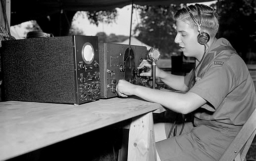
photo: Boy Scout "operating" an AR-60-T with gray panel, Output Limiter control and pilot lamp. This photo actually has the Boy Scout using the AR-60-T, the oscilloscope and the mike as "props" for this staged photograph. |
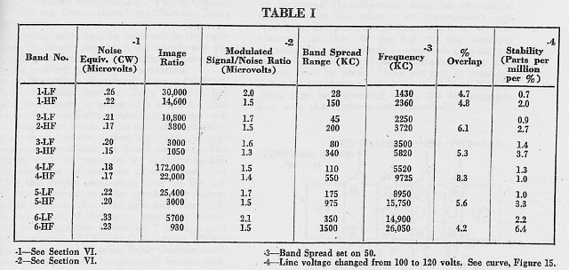
Was RCA's commercial-military receiver, the AR-60, an over-priced, over-built behemoth that produced enough internal noise that it masked all of the weak signals it was tuned to? Or, was it a "cost-no-object" design that was "built-to-order" and was so expensive no one could afford it except for the commercial-military purchasers? Not much knowledge was ever gleaned by hams from first-hand experience and many based their knowledge on a flawed review from "RADIO" magazine. Ultimately, the operational characteristics of the AR-60 remained a mystery to most. The AR-60 was available from 1935 up to 1940, an impressive five years of albeit limited production during which time a few hundred AR-60 receivers were built. This article will show the incredibly robust construction of the AR-60 and will provide performance details (including an alignment procedure) along with confirming (or debunking) all of the myths and rumors about RCA's fabulous AR-60. - H. Rogers, January 2013 |
RCA AR-60 Series |
Brief History
-
In 1935, RCA offered what must have seemed like the ultimate
communications receiver.
So over-built and so expensive that it was obviously not for any
Depression-era Ham. The AR-60 was priced at an astounding $495 at a time
when that amount of cash could easily buy a new car. However, the AR-60
was intended for commercial and military use which required a level of
design and construction that would provide the end user with a receiver
that would be able to survive harsh environments and operate reliably
over long periods of time. RCA knew the market would have to include
shipboard use that meant even more robust construction would be
necessary.
Certainly RCA had years of experience in building maritime radio equipment with their operation of Radiomarine Corporation of America which had its origins in RCA's 1923 acquisition of Wireless Specialty Apparatus. RMCA continued to build the WSA versions of the IP-501 and IP-501A shipboard receivers throughout the 1920s. These were robust receivers that were "state-of-the-art" and literally out-performed and out-survived all other commercial maritime receivers with active duty throughout the 1930s. In 1927, the U.S. Coast Guard wanted a special version of the SE-1420 shipboard receiver (the SE-1420 was the Navy version of the IP-501 receiver.) These receivers were designated as CGR-5A and were built on a contract dated June 6, 1927. These were all medium-wave receivers that were necessary for ship communications that mostly was in the 100kc to 500kc frequency range. High frequency communications was developing through the mid-twenties and shortwave broadcasting was becoming very popular by 1930. Airways communications was developing in the early thirties and required both medium wave for navigation and high frequency for communications. The commercial market included shortwave relay stations that transmitted programs for rebroadcast at lower frequencies (AM BC Band) in distant areas of the country. |
|
The need for a robustly built, commercial level of performance, high
frequency receiver was becoming obvious and by 1934, RCA was in the
design stages for a modern commercial receiver designated AR-60. Cost
wouldn't be a factor and performance was going to be at the limits of
engineering design for the technology of the time. Final design was
probably finished by late 1934. It's thought that Leland Thompson was in
charge of the electrical design and John Terrell was in charge of the
mechanical design. All production and test for the AR-60 receivers was
under Engineer H. A. Robinson. The building of the AR-60 receivers was
under RCA Manufacturing Company, Inc., a subsidiary of RCA that handled
commercial and military equipment manufacturing. The fact that some wealthy amateurs might be interested in a commercial high frequency receiver was explored by placing an ad in QST. RCA did advertise the AR-60 in a few ham radio magazines, with ads like the one from the back cover of the November 1935 issue of QST shown above, but that was the only time in the five years that the AR-60 was available that it was advertised in the ham magazines. No discount dealers, like Leeds, ever offered the AR-60. Apparently, if a wealthy ham wanted the AR-60 he had to order it through an RCA dealer and the receiver would have been found listed in RCA's Broadcast Equipment catalog. The amateur market was quite different from the commercial-military market and the hams were certainly more affected by the Depression. They were much more likely to buy a National HRO from a dealer, like Leeds, where the purchase could be made with some money down followed with time payments. |
|
Early AR-60 receivers went into RCA facilities like some of their Coastal Stations. The U.S. Coast Guard was also equipped some of their Cutters with AR-60 (CGR-32-1 and CGR-32-2) receivers. Pan American Airlines used some AR-60 receiver in their direction finders. Since the final selling price was so high, very few AR-60 receivers were built. Less than 300 is the commonly accepted limited production quantity built during the period 1935 up to 1940. However, based on serial number reported that estimate might be low. If serial numbers for Coast Guard receivers indicate actual quantity by starting at 1 and ending at some higher number upon the same contract then over 300 receivers were produced just for the Coast Guard. Adding the Signal Corps and commercial users accounts for probably around 150 receivers and perhaps 50 others produced for various end users. This would total about 500 receivers produced but this is just based on reported serial numbers so the actual quantity produced could be more, perhaps a lot more. RCA built the AR-60 receivers "to order." This could be one receiver for a single order or perhaps several receivers for a commercial or military contract. One thing is obvious, the AR-60 was never a "production" receiver, it was never built on an assembly line with production run quantities in the hundreds of receivers. It seems likely that the largest quantity of the AR-60 receivers went to the U.S. Coast Guard with perhaps as many as 300 receivers built on at least three contracts between 1935 and 1940. The second largest quantity probably went to various commercial users, including RCA installations, with this accounting for probably another 50 to 100 receivers. The U.S. Army Signal Corps also ordered AR-60-G receivers and this quantity was probably around 30 to 100 receivers (three were needed for each triple diversity set-up.) This leaves the amateur market but it seems unlikely that anymore than 50 to 100 AR-60s would have made it to the hams. This totals between 380 up to 600 receivers built between 1935 and 1940 with the greatest number going to the Coast Guard.
photo left: The U.S. Coast Guard CGR-32-1 version of the AR-60R |
The Amelia Earhart - AR-60 Connection |
The July 2, 1937 disappearance of Amelia
Earhart and her navigator, Frank Noonan, near Howland Island while
Earhart was attempting a "around the world" flight is well known. How
the AR-60 receiver figured in the monitoring and post-disappearance
search has become fairly well-known due to the continued attempts by
many organizations to
unravel exactly what happened to Earhart in the last moments of her
flight.
The USGC "Lake Class" Cutter ITASCA was stationed near Howland Island on July 2, 1937 and was attempting to provide a radio bearing for Earhart. However, the ITASCA didn't "just happen to be in the area." When the USCGC ITASCA left Honolulu they were transporting some government people and some supplies for Baker Island and for Howland Island. The fact that they were going to be in the Howland Island area at the proper time was part of the plan for support that had the USCGC ITASCA providing radio beacon, communications and other navigational aid for Earhart's flight. |
Though the plan seemed like it would be especially helpful to
Earhart's flight, apparently confusion and lack of communications
protocol foiled the attempts to provide successful navigational aid.
Though some Earhart messages were copied by the USCGC ITASCA no
"two-way" communications were ever established. Earhart's
aircraft radio callsign was KHAQQ. Neither Earhart or Noonan had
proficient CW ability and
relied on voice communications only.
Besides the few radio transmissions, a "smoke screen" was also laid down as a visual marker. Apparently the smoke screen was not seen by Earhart or Noonan and it is suspected that they were already too far off course by the time it was laid down. Other speculation is that the Sun's glare off of the water prevented Earhart or Noonan from sighting the smoke screen. Earhart had earlier removed the trailing-wire antenna for 500kc transmission which would have allowed the USCGC ITASCA to use a direction finder to establish her exact bearing. In reading the USCGC ITASCA radio logs, it appears that confusing radio attempts on different transmit and receive frequencies had both Earhart and the USCGC ITASCA radiomen unable to establish any two-way communications. The last confirmed Earhart transmission received by the USCGC ITASCA indicated that her plane had about ten minutes of fuel left but that Earhart would listen for a beacon signal to be sent 30 minutes later. This contradictory transmission seems to be indicative of the confusion that was being experienced by both Earhart and the USCGC ITASCA radiomen. The AR-60 Receivers on the USCGC ITASCA - The USCGC ITASCA was equipped with two AR-60 receivers although the receivers were certainly the CGR-32-1 types, the Coast Guard version of the AR-60-R. Some of the speculation on Earhart's position has been based on USCGC ITASCA radioman's signal strength reports. The AR-60 doesn't have a Carrier Level meter and therefore the QSA reports were estimations by the radioman. The QSA system uses levels 1 (weak) to 5 (strong) to report signal strength and the USCGC ITASCA was using signal strength to estimate Earhart's distance. In the case of the last Earhart transmission received on the USCGC ITASCA, the signal was so loud one of the radiomen had to check visually that Earhart's plane was not flying directly over the Cutter. |
|
photo above: USCG Radio Op with CGR-32-1 receiver |
Post-disappearance there were several tests performed in trying to
determine where Earhart had actually went down. Some of these tests
involved PanAm High Frequency Direction Finding stations that were
located at four points in the Pacific and provided bearings for
the PanAm Transpacific Clippers. These stations were also equipped with AR-60
receivers. Today, there are several organizations that are still researching the mystery of Amelia Earhart's disappearance. In fact, Collins-Rockwell assisted in one project that involved using a "loaned from the AWA" and functional AR-60 receiver to determine the possible distance of Earhart from the USCGC ITASCA by using the estimated signal strength reports from the USCGC ITASCA's radio logs. One of the performance comparisons drawn by Collins-Rockwell was between the RCA AR-60 and its contemporary, the Hammarlund Super Pro SP-100. In mid-1937, the RCA AR-60 was considered the "state-of-the-art" commercial receiver with the Hammarlund Super Pro also being a top quality professional communication receiver. The Super Pro featured double pre-selection on all bands with direct frequency readout that was accurate to half a percent, bandwidth controlled with variable-coupled IF amplifiers, tuned-amplified AVC and high fidelity audio. The Super Pro was an advanced and thoroughly modern receiver while, in reality, the AR-60 was seriously beginning to show its age by 1937. However, the AR-60 was a highly reliable and durable receiver, especially at sea. Something that couldn't be said for the Super Pro. The photo left is from KN4R who found it in a video that is available on You Tube. This short video shows a lot of late-thirties equipment (and some later gear, too) with some info on the hypothesis that AE landed on a reef and was able to transmit signals from that location. Click for link here: AE VIDEO |
Circuit and Construction |
The AR-60 was built on a heavy-duty nickel-plated brass chassis with
nickel-plated brass bottom covers. In fact, most of the receiver is
built with non-ferrous metal to reduce salt-air corrosion when on board
ship. All ferrous metal components were heavily cadmium plated to
prevent corrosion. The front panel is .190" aluminum. Underneath, the chassis is sectioned off with shielded
compartments and when the three bottom panels are installed, each
section is completely shielded. The receiver tunes from 1.5mc up to 25mc
in six tuning ranges. The bandspread range gives high resolution vernier effect
because its span was limited to an average of about 100kc for the entire bandspread range (although its exact span depends on the tuning range
selected and where you are tuned with the main dial in that range.) The
AR-60 front-end uses double pre-selection or two TRF
amplifier stages, on the three highest tuning ranges, or from 5.6mc up
to 25mc. On the three lower frequency ranges, a single RF amplifier
stage is utilized, or from 1.5mc up to 5.6mc. Most radio engineers at that time generally thought that double preselection was only for image rejection and not really necessary below
around 7 mc where the receiver performance was more efficient. The AR-60 receiver featured an elaborate antenna input
system with selectable links for doublets or end-fed wire antennas and
then variable antenna primary coupling allowed the operator to adjust
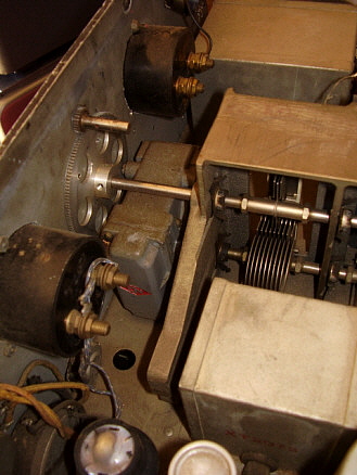
how much signal level was going to be needed for low-noise reception. All of the RF coils were wound on ceramic forms, however all of the front-end coils are tapped for the six tuning ranges (rather than using separate coils for each range.) The tuning condenser is a massive unit that was built by Hammarlund Mfg. Co. Inc. for RCA. The cast bronze frame allows for mounting both the main tuning condenser and the bandspread condenser. The audio output is from the single 41 tube that uses a 600 Z ohm output transformer. |
|
|
The B+ levels are fairly low in the AR-60 so only
about 1/2 watt of audio power is available and since the receiver was
designed for commercial use, headsets were the intended
audio reproducers. Most of the capacitors used in the circuit are Faradon/RCA types or
capacitor blocks mounted in metal cans. The AR-60 receivers were all
equipped with covers over the IF transformer adjustments to deter any
tampering with the alignment. Three IF amplifier stages are used with a
Crystal Filter provided. The intermediate frequency is 750kc. All IF
transformers are wound on ceramic forms. Two of the
tubes used are multifunction types with the 6B7 providing 3rd IF amp, AVC and detector functions and
the 6F7 providing 1st AF amp and BFO functions. The other tubes used are
6D6 and 6C6 in the front-end and IF section with a 41 audio output tube
and an 84 rectifier tube. Ten tubes are used in the AR-60 and a 991 neon
regulator is also provided for the LO. Due to the massive tuning
condenser and the regulation used on the LO (along with the fairly low
B+ levels,) the AR-60 is a very stable receiver with very little drift.
The AR-60 can be operated on batteries although it requires accessing the terminal boards in the power supply section of the receiver to move some wires and add the battery cable. An access hole for the battery cable is located next to the AC input socket. Once battery operation is set-up the receiver cannot be operated on AC unless the wiring is changed back. Some AR-60 receivers were equipped with an Output Limiter circuit. The five step OL control is mounted just to the left of the tuning dials. Output Limiters were used to allow headset listening to a signal at a desired level and to prevent the audio from being driven higher by static discharges or other noise pulses. The Output Limiter generally saved the radio operator's hearing and also helped reduce "listener fatigue." Some AR-60 versions will also be found with a pilot lamp (with green jewel) installed to the left of the tuning dials. Prior to a pilot lamp installation there wasn't a visual indication that the receiver was powered up. All pilot lamps appear to be "end user" installations but all are almost identical which implies that instructions or kits were available from RCA. The AR-60 was available as a black finished table model (suffix T), as a rack mounted unit with full dust cover (suffix R) or in a deluxe two-tone gray table cabinet (suffix S.) It appears that late in production the rack mount receivers (and the table versions) were available with gray painted panels. Note the header photo showing a Boy Scout posing with an AR-60-T version in gray with OL control and pilot lamp. Also, late in production some AR-60 receivers may have come equipped with later octal tube equivalents of the normally used large six and seven pin tubes, e.g., 6K7 for 6D6, etc. |
Under Chassis Details |
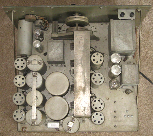
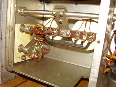
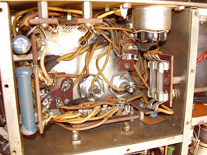
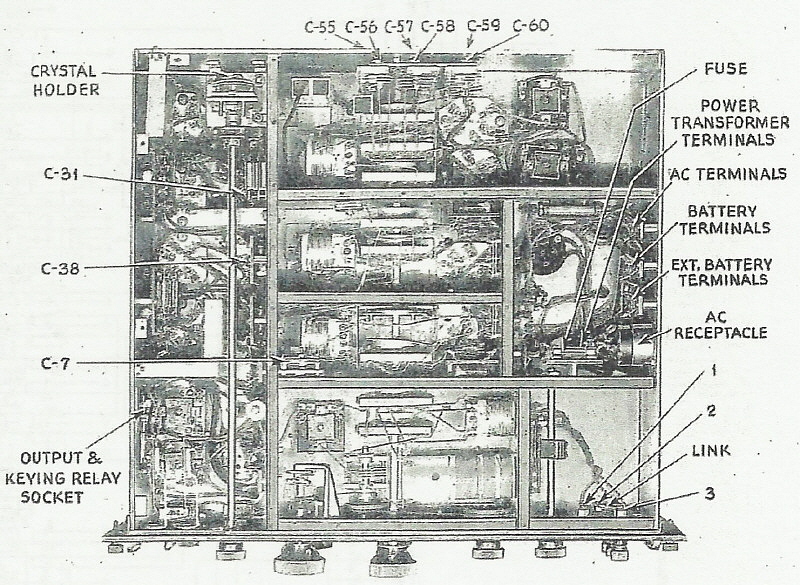
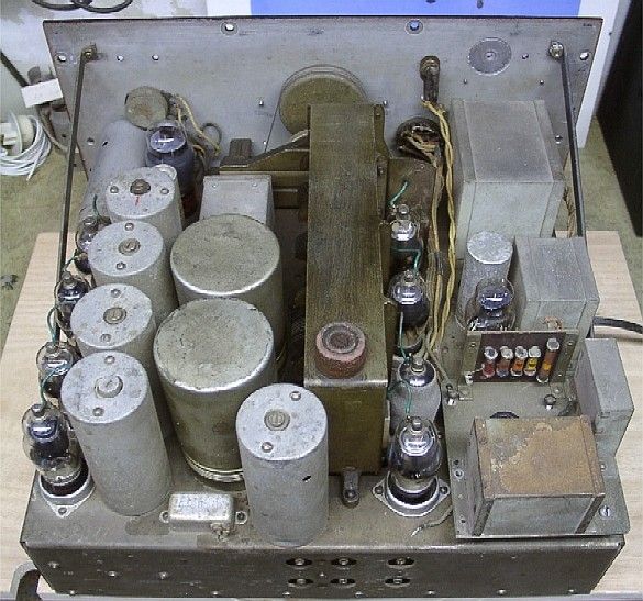
One look under the AR-60 chassis and you can tell that the receiver couldn't have been built on a production schedule. These receivers literally had to be "built to order" with all construction being accomplished "by hand." In the photograph to the right, which is of the CGR-32-1 version of the AR-60, the receiver is oriented on its side with the antenna input terminals to the lower left. Starting at the lower left, this is the antenna input terminal board location. Note the thumbscrews that allow moving a link to select either balanced or unbalanced antenna inputs. Just visible in this section is the shaft that is the variable coupling control which carries the two antenna coils. Note the cut-out in the side of the chassis in this section - on all types of the AR-60 receivers other than the CGR-32-1 this area is an access cut out for the three side-mounted antenna jacks. Just above the antenna input section is the antenna coils and antenna trimmer section. Note that the two antenna coils are mounted with a silk-insulated copper screen between them and the coupling coils. This copper screen prevents electrical coupling but allows magnetic coupling. This tends to keep the input impedance constant and results in lower noise inputs. The Antenna Trim condenser is driven with two fiber pulleys. Also note the drive for the Band Spread tuning uses a cast mount for the rear of the shaft. Behind the antenna coils/trimmer section is the 2nd RF Amplifer section. Note the two trimmer capacitors. The upper one is C7 and the lower one facing down is C9. The Mixer section is next and note the trimmer facing down. This is C16. Behind the Mixer is the Local Oscillator section. The section that is bottom center contains the AC power input, power transformer wiring and filter wiring. Usually the fuse holder is mounted in this section but on some receivers it will be found on top of the chassis for easier access. The accessory socket behind the power supply section is an end-user addition to provide battery operation and remote standby of the receiver. The top section far right is the Crystal Filter assembly. The crystal is actually mounted inside the ceramic base of the Phasing condenser. The crystal is secured with a screw mounted metal plate on the back side of the condenser mount. Just visible above and behind the Crystal Filter shaft are two of the adjustments for the IF transformers. The audio section is to the left with the two phone jacks. The audio output is also accessible from a socket and a terminal board from the side of the chassis (note the cut-outs for the socket and terminals on the side of the chassis.) Note that all capacitors are either Faradon square-open types or wax-potted paper caps mounted in metal housings. All adjustment trimmer capacitors are air-variables. When the bottom covers are installed each section if fully shielded. Note too that the chassis is NOT steel but is nickel-plated brass as are the three separate bottom covers. |
photo above: Underneath the CGR-32-1, USCG version of the AR-60-R receiver |
|
|
|
|
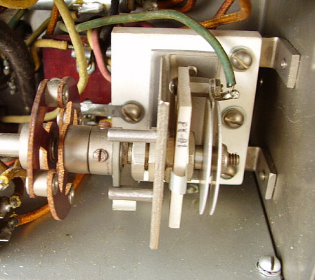
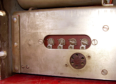
photo leftt: Part of the ceramic band switch sections. These
ceramic stators are held in place with adjustable set screws that are
mounted to the center bottom plate. The adjustments are to limit the
movement of the ceramic stators to prevent shaft binding due to
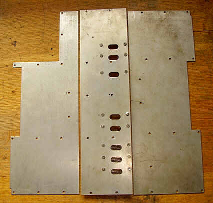
misalignment. (CGR-32-1) photo right: These are the three nickel-plated brass bottom covers. Note that the center cover has the adjustable set screws and locking nuts for setting the proper clearance between the screws and the ceramic stator of the band switch sections. These covers are from a CGR-32 receiver which has a slightly different cover for the antenna input and power supply section. Note that the large cutout upper left of the cover. This leaves the antenna input terminal board accessible when the cover is installed. |
|
|
|
AR-60 Model Types |
AR-60-S - This was the Deluxe version with two-tone gray finish. The
top cover-cabinet was aluminum metal painted smooth gray. The receiver sat on a wooden base to
that was also painted smooth gray. The panel was a slightly different shade of
gray and was "ripple finish" (RCA's advertising name for
wrinkle finish - which is the name used in the RCA AR-60 manual.) Dials and control escutcheons were light
silver color with black nomenclature. This is the version generally seen
in all advertising from RCA and consequently is the most often seen
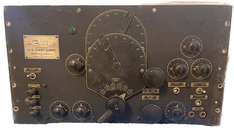
photo version of the AR-60. Selling price was $495. AR-60-T - This was a Table top version that had a black "ripple finish" panel with black dials and escutcheons on the early versions. Later versions had gray "ripple finish" panels. The panel is the same width as the aluminum cabinet which was "ripple finish" painted the same color as the panel. Selling price was $485. Some "T" receivers may have been supplied with a painted wooden cabinet (see K4RAR Collector's Gallery.) AR-60-R - This is the Rack mounted version that had a black "ripple finish" panel with black dials and escutcheons on early versions. Later versions had gray "ripple finish" panels. The 19" wide panel had rack mounting holes not the usual slotted openings. The aluminum dust cover was painted smooth finish black and secured with two rear thumb screws that are on the rear of the cover. The dust cover entirely encloses the receiver chassis (top, bottom, back and both sides.) Selling price was $475 AR-60-G - This was the U.S. Army Signal Corps version. Unfortunately the only known Signal Corps' photo shows two different types of AR-60 receivers. Specifics are not known at this time but receiver was certainly an AR-60-R version with some changes for Signal Corps use. It appears from the Signal Corps' photo (shown below) that both black and gray panels were used. CGR-32-1 & CGR-32-2 - Special U.S. Coast Guard versions with black "ripple finish" panel, black dials and escutcheons. Receivers are basically the AR-60-R with some minor changes. The first contract for AR-60-R receivers used by the USCG could have been designated as CGR-32 with no specified "dash number," although this hasn't been confirmed. It might be possible that the earliest AR-60-R receivers used by the USCG didn't even have the special CGR designation at all and were merely AR-60-R receivers. Certainly by 1937, the Coast Guard designation of CGR-32-2 was in use (CGR-32-2 SN: 103, contract Tcg-26741, dated March 12, 1937 resides in the Hammond Museum in Ontario) which implies that perhaps a CGR-32-1 contract existed before 1937. So far, the only confirmed USCG models are CGR-32-2 and CGR-32-1. Our (Western Historic Radio Museum) Coast Guard receiver is CGR-32-1 SN:25, contract Tcg-31939 dated November 16, 1939. USCG CGR-32-2 from Tcg-27470, 24 June, 1937 sn: 138 (KN4R - 2023) Andy KD6TKX owns a CGR-32-2 with a different set of numbers. It has an "order number" rather than a "contract number." The info is: CGR-32-2 SN:101, order TIPB 1651, date May 1, 1937. As RCA Manufacturing Company, Inc. supplied the USCG with receivers, it's probable that the initial batch of receivers were built under a specific contract number with later receivers being built with the same CGR-32-1 or 32-2 designation but under different contract numbers. This would be the same situation as the more modern R-390A receivers that always have the same designation (R-390A/URR) but were built over a period of several years under many different contracts. I would expect that only a few CGR-32-1 and -2 contracts were issued between 1935 and 1939. Each of these contracts were probably for small quantities of the receivers. One has to remember that this time period was long before WWII and the demands of the military in the 1930s were minimal. Contracts from that time period are generally for 100 (or more often less) units per contract. According to Chief Radioman Leo G. Bellarts, in an article titled "KHAQQ Calling ITASCA", the receivers used on the ITASCA in July, 1937 were CGR-32-1 types. Although this designation is outside of Bellarts' quote and was added by the authors (David Bellarts and David Bowman) the information must have come from Leo G. Bellarts. Other sources also identify the USCG ITASCA receivers as CGR-32-1. A "new contract" for the CGR-32-1 was issued for the Coast Guard on contract Tcg-31939 dated November 16, 1939. This was probably the last contract for CGR-32-1 receivers. Some of the variations noted on the 1939 CGR-32-1 included removal of the side antenna input jacks, possible relocation of the AC fuse board from under the chassis to top of chassis, modification of left side bottom cover with cutout portion to allow access to antenna links. Whether all CGR-32-1 receivers have these variations is not known at this time. These last "contract" CGR-32-1 receivers were supposedly to be installed on the newly rebuilt "Lake Class" Cutters (ca. 1940.) It is generally thought that about 30 "last contract" CGR-32-1 receivers were built but perhaps this was the typical quantity of any of the CGR-32 contracts. At present, we don't have enough information to report on what the exact differences are between the CGR-32-1 and the CGR-32-2 versions. |
AR-60 Details and Variations |
Data Plate
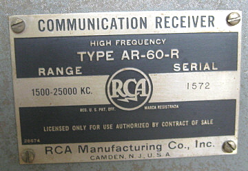
Versions - The earliest Data Plate featured the
RCA-Victor emblem, which is the RCA "meatball" logo to the left and "His
Master's Voice" or "Nipper" logo to the right. This type of data plate
appears in most of the advertisement artwork used for the AR-60 and is
shown in photo 1 right. Later receivers will have a modernized data
plate that is shown in
photo 2. It is interesting to note that these two tags state "licensing
only for use authorized by contract of sale." This implies that some
sort of agreement was necessary to purchase the AR-60 receivers and
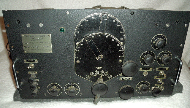
implies commercial use. Photo 3 shows the data plate used on the USCG version CGR-32-1
Tcg-31939
receivers. Photo 4 shows the data plate from USCG CGR-32-2 from
Tcg-27470, 24 June, 1937. Note the different layouts and different fonts
used in the two USCG tags
|
1 |
2 |
3 |
4 |
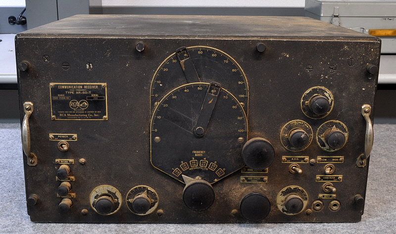
Panel Colors - The panels used on the AR-60 series were .190" aluminum. The rack mounted panels have properly spaced holes for mounting rather than the typical "rack slots." Early AR-60-R and AR-60-T versions use "Black Ripple" finish paint which was a very heavy wrinkle finish. The deluxe AR-60-S used a gray ripple finish panel upon introduction. Late in production, probably around 1939, the AR-60-T and AR-60-R panels were also finished in gray ripple but whether this was optional is not specifically known. The 1939 RCA Broadcast Catalog doesn't mention optional panel colors for the AR-60. The AR-60 manual calls the paint black or gray "wrinkle" finish. | Pilot Lamp - It will be noted that the early advertising shows the AR-60 versions without any visual indicator that the receiver is actually powered-up. Many (most?)examples of the AR-60 have a green jeweled pilot lamp installed to the left of the tuning dials. Note that the vintage photo of the Boy Scout/AR-60 shows a pilot lamp installation on a gray panel receiver. Then compare that to the contemporary photo of the gray panel receiver SN 1572, which doesn't have a pilot lamp. It's unlikely that RCA built the AR-60 with the pilot lamps installed, so why are many examples equipped with a "green jeweled" pilot lamp? Possibly there was some direction from RCA on pilot lamp installation that was available for commercial-military users. The pilot lamp installation is always in the same location and the work always appears to be first class, dealer level work. | Output Limiter Control - Three examples of AR-60 are known to have this control. One is shown in the header photo with the Boy Scout, one is owned by PE1NGZ in the Netherlands and one is owned by KD6TKX. The Output Limiter required an additional small chassis with several components mounted in the left rear top of the chassis. An Output Limiter would provide the user with an settable limit to the audio output level of the receiver. Below the set level, the audio is unaffected but any higher automatically "limits" the audio from increasing further. Output Limiters are for severe static conditions, especially lightning pulses or "popping" from switches turning on or off and are specifically necessary when the operator is using a headset for reception. Output Limiters were popular on shipboard equipment, especially for the Navy. It's unlikely that the Output Limiter was standard equipment on late AR-60 receivers. More probable is that this option could be installed by returning the receiver to RCA for upgrading. It's also possible that RCA sold the Output Limiter as an end-user installed kit. |
CGR-32-1 Antenna Terminal Board Bottom Cover - This bottom plate on the AR-60 completely covers the Antenna Input section and the AC power input section of the chassis. On the CGR-32-1 receivers the front section of this cover is cut out in order to allow access to the Antenna Input Terminal Board without removing the cover. This was probably done at the request of the U. S. Coast Guard for the specific contract of the CGR-32-1 receivers (Tcg-31919) to allow changing the antenna input from doublet to end-fed wire without having to remove the bottom cover of the receiver. | Power Supply and Fuses - The power transformer has dual primaries for operation of either 115vac or 230vac. As wired from the factory, the AR-60 is wired with the primaries in parallel for 115vac operation. There are two separate 6.3vac heater windings. One is for the 84 rectifier and the other winding is for the other tubes in the receiver. The AC input is fused on both lines and the fuse terminal board is located in the power supply section. This required removing the bottom cover to replace blown fuses. Some receivers will have the fuse board mounted on top of the chassis but this was certainly an "end user" modification. The exception could be the CGR-32-1 which may have had the fuses mounted on top of the chassis for easier access. | Grab Handles - These were installed all versions of on the AR-60 except for the AR-60-R. There are at least three different types of handles that were used. The original 1935 artwork shows the AR-60-S with a rounded handle that may have been the first version. The handles shown on the AR-60-R "Gray Panel" receiver and on the Boy Scout AR-60-T (header photo) are the second type. These handles appear to be thinner metal and have a decorative mounting flange. The third type are on the USCG CGR-32-1. These handles appear to be the same design as the BC-348 handles except that they are nickel plated rather than painted. The same type of grab handles are mounted on the back of the dust cover of the CGR-32-1 but these are painted black. The grab handles were never intended for lifting the receiver but are for pulling the receiver out of its cabinet. | 80 Meter Band "Split Coverage" - At first glance, the frequency coverage of Band 2 and Band 3 seem to split the 80 meter ham band. However, the AR-60 has a generous "over lap" of the tuned frequency at the upper and lower ends of each tuning range. The 80 meter band can be tuned in its entirety using Band 3 since its lower end tunes to 3.54mc with the band spread set at 50. The very bottom 40kc of the 80 meter band can be tuned by reducing the band spread below 50. |
Remote Standby Capability - The AR-60 doesn't provide the user with a specific "from the factory" method of placing the receiver into a standby mode during transmit. This is a common absence on most RCA receivers and on many commercial receivers, in general. The normal application was assumed to be a "receive only" facility. Many times, on coastal stations, the transmitting site was actually many miles from the receiving site. This make sense if there are multiple stations engaged in multiple communications where a nearby transmitting signal could interfere with reception by other operators. As a result, many commercial receivers require special modification for remote standby function. RCA did anticipate the need for remote standby and the AR-60 manual describes how the user can wire a small voltage from within the receiver that applies that voltage to the AVC line thus muting the receiver. The description advises using the Accessory Terminals or the Accessory Plug Receptacle for connection of a sending relay to accomplish receiver muting. A simple method of receiver muting was also mentioned that involved using a relay to short the speaker terminals together to silence the receiver. | Side Access
Antenna Terminals and User Accessory Terminals - Most AR-60 receivers will have three
jacks located on the left side of the chassis. The jacks will accept the
typical "banana" style plug. These jacks are directly connected to the
front antenna terminals so the position of the link on the antenna
terminal board will also affect this input. The CGR-32-1 versions do not
have these side access jacks. On the right side of the chassis there is a four screw terminal strip. Two of the terminals connect to the audio output and were for 600 Z ohm loads such as speakers, monitors or data devices. The other two terminals are not connected to anything and were there for end user applications, if necessary. The manual suggests that the two unused terminals be used for keying relay connections that would mute the receiver during transmit. It was also suggested that these terminals could be used to access the AVC line for diversity receiving applications. Below the four screw terminal strip is a plug receptacle which also was connected to the audio output and provided another way to access the receiver output. Unused pins on this plug could also be used for keying relay or diversity applications. On most AR-60 receivers the audio output transformer secondary is center tapped to chassis with the two ends of the winding providing the audio output. The CGR-32-1 did away with the center tap connection. |
End-User Installed Accessory Socket - This has been seen on two AR-60 receivers and is almost certainly an "end user" modification. The accessory sockets on both examples were on the left side of the chassis toward the rear behind the power supply section of the receiver. However, the quality of work seems to be factory or perhaps dealer level, so this might have been an option that could be added after purchase. Most likely these sockets were to allow operation of the receiver on batteries. In the CGR-32-1 receiver shown in this article, the B+, A+ and Chassis Ground are available on a five pin ceramic socket. By removing the jumpers in the plug across the B+ and A+ pins, DC can be applied to the filaments and to the B+ input (downstream of the PS filters.) Normal AC operation can be returned by removing the battery cable and reinstalling the jumpers to the plug. This made switching between AC and DC operation fairly easy. Much easier than accessing the terminal boards in the power supply section to move wires around and install a cable for DC operation and then having to undo this installation if AC operation was required. An additional possibility could be a "remote stand-by" option that would be installed by running the B+ terminals to a set of NC relay contacts that opened when the transmitter was keyed. It would also be necessary to either use a separate receive antenna or to use an antenna relay that also switched to the transmitter when keyed. Normally, the antenna switching and remote stand-by are accomplished with a single relay with multiple contacts. |
The Tuning Dials - Band
Spread Calibration - Why was the AR-60 equipped with two
dials that are only calibrated with scales that read from zero to one
hundred? At the time, direct readout frequency calibration was not all
that accurate - vague was about as good as it got. The resolution of
tuning dials at the time was also a limitation when each tuning range generally
covered several megacycles. So, how did the professional radio operators
know where they were tuned to in the spectrum? Most commercial and
nearly all military installations would have a heterodyne frequency
meter for determining accurately where their receivers and transmitters
were tuned. You, as a professional radio operator didn't care what the
receiver dial indicated since it wasn't very accurate anyway. You
verified the tuned frequency with an accurate frequency meter. Most
shipboard and military radio room set-ups will have a frequency meter
nearby. Another interesting quirk of the AR-60 is the band spread dial. Judging by the vintage photographs all users had the band spread set to 50, or half scale. This allowed the user to either tune above or below the tuned signal for various purposes. Even the alignment procedure in the manual requires that the band spread be set to 50. Additionally, the frequency versus dial readout graph shown in the manual (and shown to the right) indicates that the "Band Spread" is set to 50 for the curves to be accurate. Eventually, the standard became to have the band spread only to allow tuning below the tuned signal and for correct frequency readout calibration of the main dial the band spread had to be tuned to minimum capacitance. |
|
End-User Modifications - The modifications that show up most often are the pilot lamp addition, the Output Limiter control and the auxiliary socket. In looking at photographs and examining receivers, it appears that almost always the mods are installed in the same location and accomplished in the same manner. The quality of workmanship is almost always very good. This leads me to believe that these modifications may have been installed at RCA as part of an upgrade package for commercial or military users. This is especially true on the Output Limiter control addition since this required an additional chassis and components. This servicing and upgrading of the receivers may have been part of the purchase package and as such would not have been advertised directly in magazines. It's also possible that the commercial users had skilled technicians that were also capable of installing upgrades in a professional manner and that RCA provided parts and instructions. | Fixed-Frequency Option - The AR-60 manual mentions that a crystal-controlled LO option could be installed in the AR-60 if "fixed-frequency" operation was desired. This feature was becoming popular in receivers used at airport communication facilities and where all operations for the particular set up was on one frequency. Since Pan American Airlines was an end-user of the AR-60, perhaps some of those receivers were equipped with this option. But, it seems likely that this was an option offered but seldom, if ever, ordered. |
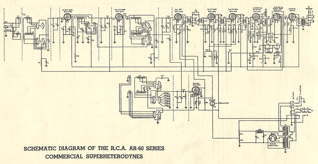
"R/9" & "RADIO" Magazine Review - Nov. 1935 & Jan. 1936 |
The AR-60 receiver was reviewed by "RADIO" magazine in the November
1935 issue and the same review was reprinted in the January 1936 issue
of the "re-vamped" magazine that was a combination of "RADIO" and "R/9"
magazines. For years, this review has affected how the AR-60 has been
written about by those whom never used an example of the receiver. The
review is generally interpreted by readers as a negative opinion of the
AR-60's ability to detect weak signals due to its high internal noise.
It is difficult to understand the review because the "RADIO" author
(he's not identified by the magazine) digresses about a third of the way
into the article into methods of IRE noise measurements and also
complains about the receiver noise specifications that were provided by
RCA. The first impression is that the author is writing about the
AR-60's inability to detect weak signals through its own internally
generated noise but he actually seems to be dissatisfied with the data
supplied in the RCA manual. If the review is read carefully (at least a
couple of times,) one can see that the author is actually peeved about
RCA's method of specifying the receiver's sensitivity in which he
believes RCA is obfuscating the AR-60's true specifications. The reader
is further confused by the author's continuing digression from the AR-60 performance into
the promotion of the Tobe-Browning method of noise versus sensitivity
specification. The complaining and comparisons continue on for about
three paragraphs after which the reader is sure the author is talking
about the AR-60's performance. When the writer's grousing and opinions
are finally finished, the review continues on and is reluctantly
somewhat complimentary. The AR-60 "RADIO" article does manage to cover
the receiver's main features and included a one graph that seems to support the author's negative opinion
of RCA's measurements. A schematic is also included. After reading several of the
"RADIO" reviews, I've come to the conclusion that the
magazine's authors were rarely complimentary towards any equipment
reviewed. I think it was just their style.
|
|
Where the AR-60 was Used |
|
|
The photo above shows an Army Sergeant operating a Triple Diversity set-up using three AR-60 rack mount receivers in each Triple Diversity Receiver. Auxiliary equipment in each rack would consist of Combiners, a Tone Keyer, Power Supplies and Control Panels. The Signal Corps used these set-ups for high-speed, mechanically sent CW (Brome.) photo from: 1943 "Training for Victory" book "RADIO-I" - the photo is identified as an "International News Photo." |
The photo above shows the Radio Room of the US Coast Guard Cutter TANEY. Unfortunately the "old coasty" website dates the photo as 1954 which is simply not possible. A more believable date would be in the late-thirties. The receivers are CGR-32-1 or CGR-32 -2 versions of the AR-60-R. USCGC TANEY wasn't a Lake Class Cutter. USCGC TANEY was of the larger and newer "Treasury Class" Cutter - note how large this radio room is when compared to the ITASCA radio room (shown in a section above.) The receivers mounted below the CGR-32s are most likely Long Wave receivers (they aren't the RCA LW Receiver designated AR-62.) The transmitters appear to be two Western Electric types for HF and a larger emergency 500kc transmitter in the center. photo from: http://oldcoasty.info/photolab |
|
|
Since the AR-60 was such an expensive receiver its use was
almost exclusively commercial or military. Other than the Boy Scout
photo shown as the header photo, I've never seen any other photos of the AR-60 being
used in a ham station. Commercial users can be seen in the following
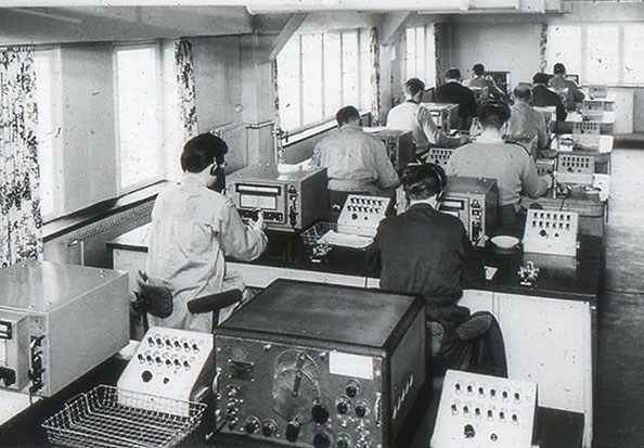
photos sent to me by KN4R. Photo left is of a Coastal Station located in Bergen, Norway
in the 1950s. The receiver in the foreground is the AR-60S version. Note
that in the very back of the room there's another AR-60S being used
(back op on the left.) Certainly the robust construction and resulting
reliability allowed the AR-60S receivers to still be in use two decades
after their introduction. The other receivers in this photo appear to
Marconi Mercury or Electra marine receivers.
More contemporary to the AR-60 manufacture is the photo right of a PanAm air station that was part of a search for a British airplane that was forced down in the Atlantic between Bermuda and New York in January 1939. The op on the left has at least two AR-60T receivers in front of him while the op on the right has an AR-60S that he is tuning. Since the op on the right has a bug on his desk, the equipment on top of the receiver might be an VFO-Exciter for a larger transmitter that's not in the shot. Also note what appears to be a very tall loudspeaker to the right of the AR-60S. |
The AR-60 Competition |
In 1935, when the AR-60 was released, there were no
receivers available that were as expensive or offered such impressive
performance. That changed rapidly when in March, 1935, National
Company began deliveries of their new HRO receiver. The HRO was designed
for performance and with its double preselection it was probably the most
sensitive receiver available. It had its drawbacks though. It used
plug-in coil sets that had to be changed for the various tuning ranges.
It used a separate power supply. Storage of the unused coil sets could
present a problem. Tuned frequency had to be determined by comparing a
micrometer dial readout to a graph-chart located on each coil set panel.
Performance was at the design level of the day but the hassle of dealing
with the accessories relegated the HRO to mostly ham service until WWII.
The receiver that truly was "the competition" to the AR-60 was officially released in March 1936 (although the SPA version was supplied to the Signal Corps in June 1935.) The Hammarlund Manufacturing Company had been developing their new Super Pro receiver since 1933 and Hammarlund was determined to offer the absolute, "no-compromise" and "cost no object" commercial receiver. The Super Pro became the second receiver to offer double pre-selection on all tuned frequencies (the National HRO was first.) Each tuning range had its own complete set of coils and condensers for precise alignment. With its practically sealed RF box and precision parts, the Super Pro was guaranteed to have a direct frequency readout dial accuracy of half a percent. Add to that the infinitely adjustable bandwidth in its variable coupled IF transformers and its 14 watts of high fidelity audio output. The SP-10 versions allowed the users to adjust RF, IF and AF gains independently and to also vary the coupling on the fourth IF amp and on the Amplified AVC for precise control of the signal. The performance was incredible and the audio reproduction breathtaking. When compared to the AR-60, the first thing noticed is that the front-end of the Super Pro is a "precision machine" with all individual coils for every function. The AR-60 makes use of tapped coils in its front-end. The front-end calibration on the Super Pro was at the design limits of the time while the AR-60 uses non-calibrated dials and the only calibration adjustments provided are trimmer condensers or "pushing turns." The IF of the AR-60 is conventional while the Super Pro's variable coupled IF was an advanced design. The Amplified AVC of the Super Pro provides superior control compared to the Delayed AVC of the AR-60. Finally there's the audio output. Since the AR-60 was designed primarily for earphone operation it's really not fair to compare its "half watt" single-ended audio to the Super Pro's 14 watt, Push-Pull, high fidelity audio. When one of the Earhart Research Organizations compared the AR-60 of 1937 to the 1937 SP-100X Super Pro, it was only because there was nothing else out there to use as a "yard stick." Actually, the Super Pro was years ahead of the AR-60 in design and performance. >>> |
>>> If there was a disadvantage to the Super Pro
when compared to the AR-60, it was in durability and reliability.
Certainly the AR-60 was built endure almost any environment and still
function. The fact that many AR-60 receivers still function on all
original parts is testament to their indestructibility. Unfortunately,
the same can't be said for the Super Pro with it's inferior Cornell-Dubilier
"TIGER"
paper capacitors and delicate fiber board parts. NO pre-WWII Super Pro
will function on all original parts and most have been repaired and
rebuilt several times over the years to keep them operational. The
Super Pro was rarely, if ever, used at sea. Like many fabulous
performers, it was a delicate instrument that had to be treated like the
Prima Donna it was.
|
AR-60 Serial Number Log |
RCA rarely used serial numbers as a chronological, sequential
identifier of a product. There always seems to be more information
embedded in the serial number. For instance, the AR-60's successor, the
AR-88, used serial numbers that contain a code for which
RCA plant built the receiver and a code for the model type that the serial
number was assigned to. However, one thing RCA wasn't, was strictly consistent.
With the AR-88, the code is adhered to during WWII but, by 1947, the
code is for the most part
discarded and only a four digit "actual" serial number used.
I've found that different serial number sequences are used for the different types of AR-88 receivers so it's likely that the different versions of AR-60 probably also use different serial number sequences. With the AR-88, the serial number is stamped into the chassis - pretty difficult to lose a serial number with that method. Unfortunately, the AR-60 is serialized on a data plate that is easy to take off and lose or discard. This, of course, leaves some compromised receivers unidentifiable. Here's what I expect to find with the AR-60 serial numbers. The first digit (from the left) will probably not be part of the actual serial number. More likely, it will identify where the receiver was built. If it is the same method that was used with the AR-88, then "1" will indicate Camden, New Jersey. It is also possible that the second number will not be part of the serial number and may actually identify the model type. For example, note the two known AR-60-S serial numbers. Both use "1" and "2" as the first two digits. I'd expect "1" to indicate "built at Camden" and "2" to indicate "S" version. Note the AR-60-R serial number. Here we have "1" and "5" as the first two digits. "1" would be Camden and "5" would indicate "R" version. The same is true of the AR-60-T receiver with "13" as the first two digits with the "13" denoting Camden-built and the AR-60-T version. The second "T" serial number has "14" which may indicate the difference between the two receivers. That is, 1304 is gray finish while 1499 is black. We will have to see several serial numbers tied to specific receivers to see if this subtle difference tied to serial numbers is ultimately true. It does seem that the few AR-60 serial numbers available at this time are four digit numbers. If the AR-60 used the same encoding that the later AR-88 did then we can expect that the first two digits are codes and only the last two digits are the serial number. >>> |
>>> Any military AR-60s are likely to be serialized
differently. My CGR-32-1 (SN: 25, contract Tcg-31939 dated November 16,
1939) receiver has its original U.S. Coast Guard data plate with the
serial number of 25. This is likely a sequential
numbering of the approximately 30 (?) CGR-32-1 receivers built on that
contract. The
CGR-32-2 receiver that resides at the Hammond Museum in Ontario is
serial number 103 on contract Tcg-26741 dated March 12, 1937. This
confirms that there was more than one contract of CGR-32 receivers built
for the USCG with different designations and different contract numbers.
Whether the SN of 103 on the Hammond CGR-32-2 is a sequentially assigned
number is not known. While it is possible that over 100 receivers were
supplied on this contract, it seems highly unlikely given the low
demands of the military in the thirties. It is possible that the initial
"1" indicates "built at Camden" as would be typical for RCA's code and
then the SN would be "03" although that would be just speculation at this
time. Serial number 132 has been found, a CGR-32-2 receiver in complete
condition. The Signal Corps AR-60-G versions have their own specific data plate specifying that the receiver is for the "Signal Corps U.S. Army." The order number is 10865-NY-35 on the one reported AR-60-G and its serial number is 14. This seems to follow the Coast Guard versions closely. Date on SN 14 is 6-20-35. AR-60 SN LOG: The serial number log is the best way to find out all of this information. It has worked very well indeed for the AR-88 where we have collected nearly 100 examples of serial numbers (in concert with Alan Ford who operates an AR-88 SN log out of Australia) for all of the different versions. Although it is generally thought that very few AR-60 receivers have survived, I'm always surprised at how much gear is really out there. If we don't ask, we'll never know. So, if you're an owner of one of the versions of the AR-60, send us the serial number and we'll add it to the log. Our serial number logs have been extremely helpful in dating receivers and estimating production levels. We will consider (for now) that the S version had its number sequence, the T had another and the R another. The military versions will have to be listed by their data plate numbers including the Contract or Order Number. Please when sending in your AR-60 serial number be sure to include what specific type receiver it is, S, T, R or military.
Send your serial number to: WESTERN HISTORIC RADIO MUSEUM AR-60 LOG |
AR-60- S:
1213, 1226, 1268
AR-60-T: 1304, 1499
AR-60-R: 1304, 1572, |
AR-60-G (Signal Corps):
14,
CGR-32-2 - Tcg-26741 (Mar
1937), TIPB1651 (MAY 1,
1937)
and Tcg-27470 (June 1937) - (Coast Guard):
CGR-32-1 - Tcg-31939 - Nov 1939 (Coast Guard): 25,
|
AR-60 Maintenance, Alignment and Restoration Hints |
IF and RF Alignment of the AR-60 Receivers Thanks to Jon Wiener, Brian Harrison and Peter Greene, I was able to obtain a copy of the original AR-60 manual. This has allowed me to provide some details on how RCA intended their receiver to be aligned. To attain the best performance, the receiver must be aligned exactly as described in the RF tracking procedure below - it is just like the one in the manual. The IF alignment from the manual is adequate but the procedure I use, as shown in "IF Alignment," will result in a more accurately set IF and a better performing Crystal Filter. NOTE: WA6OPE donated an original AR-60 manual in 2023 - Thanks Tom! |
IF Alignment
- The Intermediate Frequency is 750kc but since the AR-60 has a Crystal
Filter, the IF must be aligned exactly to the particular resonance of
the crystal in the filter. I find it best to align the IF of receivers
that have Crystal Filters, with the Crystal Filter on. That way you are
sure to end up with a working filter that is an asset to reception. There are five transformers that require alignment. Two are tuned input and tuned output with trimmer adjustments on the bottom of the transformer. This will require removing the bottom plate for IF alignment. Although it is pretty tight quarters these trimmers are easy to access. The remaining transformers have one trimmer adjustment on top. Alignment protectors must be removed prior to beginning the alignment. These merely require that the mounting screws be removed. It might be a good idea to reinstall at least one screw to secure the trimmer condenser. Connect a signal generator with 1000Hz modulation to the Mixer input. Connect to the receiver tuning condenser through a .01uf cap. Connect an Audio Output meter to the receiver output. Set the receiver to AVC off, AM reception with the Audio Gain about half advanced and the Sensitivity half advanced. With the receiver set on the lowest tuning range, tune the signal generator through the 750kc range. You will hear a 1000hz tone which you will center in the receiver IF passband. Check your signal generator's digital frequency counter to see where the IF is currently adjusted to. It will probably be around 750kc. Now turn on the Crystal Filter and set the "phasing" control half advanced. Now sweep through the IF passband with the signal generator. You will find one narrow frequency that "peaks" as you tune through. This is the crystal's resonant frequency. With the signal generator set a the crystal frequency, adjust all of the IF trimmers for maximum output indication on the Audio Output meter. It doesn't matter what order they are adjusted. You'll probably have to reduce the signal generator output level as each transformer is peaked. Now, adjust the Crystal Filter for minimum bandwidth with the "phasing" and repeat the IF trimmer adjustments. This completes the IF alignment. When you connect the receiver to an antenna you'll find that when the Crystal Filter is turned on there will be just a "slight" decrease in signal strength but it will be very apparent that the bandwidth has narrowed significantly. By adjusting to opposite side of minimum bandwidth with the "phasing" you will be able to reduce heterodynes. By aligning the IF with the Crystal Filter on you'll get the very most out of any receiver equipped with this type of selectivity device. |
|
BFO Alignment - Once the IF section is in alignment the BFO can be aligned. You'll probably find that the BFO can also has an alignment protector installed that will have to be removed. In order to gain access to remove the alignment protector, you'll have to remove the 6F7 tube and the 6B7 tube. Once the alignment protector is removed, reinstall one screw to secure the BFO trimmer condenser. Reinstall the 6F7 and 6B7 tubes and power up the receiver. After a warm-up of about 10 minutes you can proceed with the BFO alignment. With the signal generator connected to the Mixer section of the tuning condenser, input an unmodulated sine wave at the Intermediate Frequency. The BFO of the receiver should be turned on and with the BFO control tune the BFO slowly through its range. What you are looking for is the point where the pitch of the heterodyne is highest and then immediately begins to go lower in frequency. This is minimum capacitance on the BFO control. Now rotate the control 90º counter-clockwise. This will have the BFO control in the middle of its range with it decreasing capacitance as its rotated clockwise. Now adjust the trimmer at the rear of the BFO can for zero-beat. If necessary, remount the BFO knob so that it is set for zero. Check the BFO control operation by rotating each side of zero and noting the the heterodyne frequency increases on each side of zero. Power-down the receiver, remove the 6F7 and 6B7 tubes to reinstall the alignment protector and then reinstall the tubes. This completes the BFO alignment. |
RF Tracking Alignment
- Set
Band Spread dial at 50 when aligning RF Tracking. Set the Main Tuning dial to 100. It doesn't matter where the Antenna Trimmer
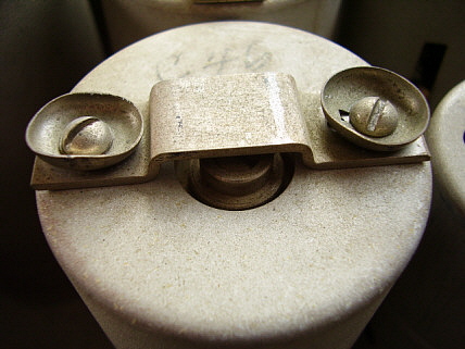
is set since there are no adjustments to the 1st RF amplifier. Check C16 - This is the Mixer trimmer that sets the grid load. This was adjusted at the factory and shouldn't be changed. There should be a red mark on both the rotor and stator plates. These two red dots should be coincident. It's possible that the adjustment has been moved but these two red dots show the correct setting for the proper grid load on the mixer. This adjustment must be performed first before the RF Tracking. C16 is the only trimmer located in the mixer compartment. It is not marked on the component location drawing. My CGR-32-1 didn't have the red dots on the rotor or stator plates but there was a red paint that was on the slotted adjustment part of the trimmer instead. I adjusted C16 to "line up" the red paint. Local Oscillator Adjustments - All trimmers except C60 are adjusted with the Main Tuning dial at 100 and the Band Spread at 50. Don't adjust the receiver dials, instead tune the signal generator to the receiver's set frequency. You can also just use receiver noise. Use an audio level meter connected to the 600Z audio output to monitor for correct peak level output. Here are the LO trimmers. C55 = Band 1 C56 = Band 2 C57 = Band 3 C58 = Band 4 C59 = Band 5 C60 = Band 6 Trimmers are located on rear of chassis, accessible thru holes in chassis rear apron. Below is the location of the LO trimmers as viewed from the rear of the chassis. -------Top of Chas. ----- C-55 C-57 C-59 C-56 C-58 C-60 -------Bottom of Chas.-----
After aligning Bands 1, 2 & 3, remove bottom covers before aligning Bands 5 and 6. You will do Band 4 after completing Bands 5 and 6. Adjust Band 6 first. Trimmer C60 is adjusted with the Main Tuning set to 20. Also adjust C9 on Band 6 with MT at 20. C9 is not shown on the component location drawing but the location of C7 is. Since C7's location is marked then the other trimmer in the 2nd RF compartment is C9. See component location drawing below. The peak level adjustment on C9 is difficult to hear so use an audio level meter to indicate proper peak level. Set receiver to Band 5 and MT to 100. Adjust C59 for maximum indication. Then adjust C7 for maximum. C7 adjustment is similar to C9 and requires an audio level meter to set properly. Reinstall bottom covers. Return to Band 6 with MT at 20 and readjust C60 for maximum. Change to Band 5 with MT at 100 and adjust C59 for maximum. Switch to Band 4 and adjust C58 for maximum. All RF Tracking adjustments must be performed in the order described above for proper alignment of the receiver front end. These are the only adjustments to the front end alignment. Inductance adjustments were made at the factory by "pushing turns" and other methods that today are not really "adjustable." By accurately adjusting the trimmers provided at the high end of the dial on each band good tracking should result. This method is very similar to that used in the BC-348 aircraft receivers. |
Component Location Drawing
Shown to the right is the component location drawing from the RCA AR-60 manual. Of course, it's not very complete but provides enough information for alignment purposes. It's fortunate the the manual also provides a very detailed wiring drawing that does locate all components and how they are wired into the circuit. In the drawing shown for alignment purposes the upper most compartment is the LO. Following the band switch shaft,... The second compartment from the top is the Mixer. The third compartment from the top is the 2nd RF The fourth compartment from the top is the 1st RF/ANT
Also, reference the photo of the underneath of the CGR-32-1 that's in a section further above in this article "Under Chassis Details." The trimmers C16, C9 and C7 are shown in this photo and their location described in the text. |
|
|
Band Switch Ceramic Stator
Adjustment - The eight sections of the band switch
assembly are made up of ceramic stators and shaft-driven rotors. The
position of the stators is somewhat maintained by the heavy TC wire used
in the circuitry. However, RCA provided adjustable "stops" to prevent
excessive movement of each of the stators while the band switching is
taking place. Excessive movement could cause binding and misalignment
between the rotor (arm) and the stator. The stator is the ceramic mount
for all of the silver contact disks that make up the stationary portion
of the switch. The adjustments consist of 6-32 threaded rods that are slotted on one end. These thread into the center bottom cover and are secured after adjustment with a 6-32 locking nut. The proper adjustment is approximately .005" clearance between the stop (the end of the threaded rod) and the edge of the ceramic stator. The procedure is to loosen all of the adjustment screw nuts. Then, one by one, adjust each screw until it just touches the ceramic stator and then just slightly back out the screw leaving approximately .005" clearance. Then tighten the lock nut and proceed to the next adjustment screw until all 16 adjustments have been made. Cycle the bandswitch through its positions and then recheck the settings. If your AR-60 is missing the bottom covers or is missing the center cover with the adjustment screws then a replacement bottom should be made and installed. The replacement must have the 6-32 threaded rods so the bottom cover has to be thick enough to allow for tapped holes. The original cover was .060" brass that was nickel-plated. If you don't have the bottom center cover then repeated use of the band switch without this cover installed will eventually cause mis-alignment of the switch stator which will cause intermittent operation on some bands. It's also possible that long-term use with the bottom plate not installed could cause breakage of the solder joints due to movement of the switch stators and relative stiffness of the buss wiring. |
Dial Pointer
Index Repair - The dial pointers have an opening at the
top that has an wire mounted on the back side of the pointer to act as
an index. The wire is very fine and any sort of mishandling of the
pointer will damage the wire index. Fortunately, it's fairly easy to
repair the wire index or make new ones if they happen to be missing.
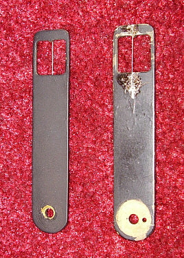
To remove the pointers, first unscrew the pointer mounting screw. The pointer has a locating pin so it can only mount to the hub one way. If you have to remove the band spread pointer then remove the main tuning dial. It's mounted with three screws that are threaded into the panel and utilize spacers to maintain the correct clearance between the main dial and the band spread dial. Now you have access to the band spread pointer which is mounted to its hub the same way the main dial pointer was mounted to its hub. Turn the pointer over and you'll notice that the index wire is held in place with a small amount of solder. The wire actually mounts in an incise and is secured with solder. If your index wire has come lose all that is required is to place the lose end back in the incise and apply a small amount of solder. After the solder is set up, file the solder as flat as possible and then paint the area with black paint. If the index wire is missing, use very fine tinned copper wire, like a single strand from a piece of 22 or 24 gauge stranded wire. This is usually about the right size but compare to a good index wire if you have one. The wire should be silver in color. Your incises can be cut by using an Exacto knife. Since it's solder, it will be easy to cut out the old solder and have the incises open. Now lay the new wire into the incises and hold with the Exacto knife blade while flowing the solder across the incise. Once one end is secure pull the wire tight and lay it into the other incise and solder it in place. Using a file, remove as much solder as possible to get the back of the pointer flat. Paint the soldered area black Install pointers and the main dial and check to make sure the new solder doesn't rub the dials. In the photo to the right, the repaired index wire is on the right. It hasn't been painted (yet) to show what the repair looks like. |
|
|
AR-60 Receiver Profiles - Collector's Gallery If you own an AR-60 receiver, how about sending in a photo? Tell us a little about your receiver and I'll add it to this gallery. Full credit for your photos and write-up. Send your AR-60 photos to this e-mail address: WHRM - AR-60 PHOTO |
|
CRG-32-1/Tcg-31939 SN:25 - U.S. Coast Guard AR-60R WA7YBS The CGR-32-1 Tcg-31939 versions are the last of the U.S. Coast Guard versions
of the AR-60-R receivers that were built on a contract dated November 16, 1939. At
the time, the USCG was rebuilding and refitting their ten Lake Class
Cutters, the new receivers to be installed were these CGR-32-1 types.
Since there were only ten Lake Class Cutters only a handful of these
"last contract" CGR-32-1
receivers were built.. Estimates are a total quantity of
thirty or so receivers were built under that contract. In 1941, the ten Lake Class Cutters
were "loaned" to England as part of the Lend-Lease Act. According to the USCG
website much of the gear, accessories, tools and other "sensitive" items
were removed from the Cutters before the transfer to England.
Apparently, the British installed their own equipment upon receipt of
the Cutters. If the receivers were removed, then it's likely they were
used elsewhere, perhaps for USCG use or maybe they were utilized in
other areas for the war needs. At any rate, this particular CGR-32-1
ended up in one of the shipyards in Richmond, California sometime after
WWII. It was at this point it was removed from shipboard use and became
the property of an individual who worked at one of the Richmond shipyards and
collected electronic gear. Fast-forward to 1968, when the receiver was
sold by the "gear collector" to a young teenager who was an aspiring ham. Although a ham-ticket was never
attained, the receiver was kept in original condition and used as a
shortwave receiver now and again. After owning this CGR-32-1 for over
forty years, this longtime owner sold his CGR-32-1 to me in December 2012. |
Normal Problems
- This receiver is very original with the exception that, as with many
older pieces of electronic gear, the two power supply filter capacitors
are replacements. Otherwise, this CGR-32-1 is functional on all original
parts. When I got the receiver it did have two modifications that did no
damage and were easy to remove. The first mod seemed to have been a
"quick fix" that had a 6.3vdc filament transformer mounted on a
butch-plate on the rear left top of the chassis. This transformer
provided the heater voltage for the tubes in the receiver. I thought it
was highly unlikely that anything was wrong with the original power
transformer and a check found that indeed the proper filament voltage
was present. I traced the wiring and found that the auxiliary socket,
which apparently was for operating the receiver on batteries, required
jumpers in the plug and, although the B+ was jumped, the A+ wasn't. All
that was required was to install the A+ jump in the plug and remove the
mod transformer to have the receiver operating on its own power
transformer again. The other mod was the addition of a frequency chart
to the front panel. The chart was nicely done but it was obvious that it
was from a BC-375 Tuning Unit. To correct this mod required removal of
the chart frame, plugging the mounting holes and touching up the paint.
Then the data plate was moved back to its original mounting holes to
complete the mod removal.
|
|
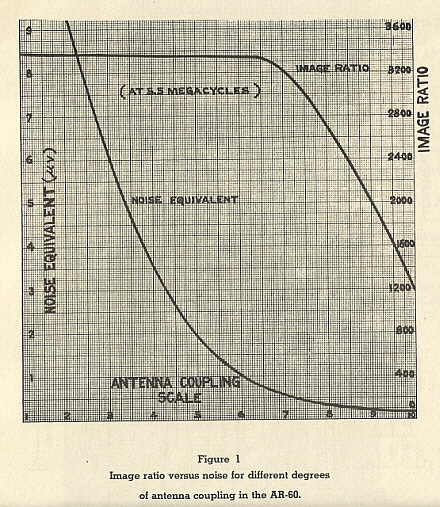
The CGR-32-1 performance is impressive and can in some ways be compared to the Hammarlund Super-Pro SP-100 in overall front end noise and sensitivity. It's similar to the 1940 Navy RBB and RBC in its audio output capabilities since these receivers were designed for headset operation. Signals are easy to tune with the Band Spread control since its vernier effect results in about a 100kc spread from 100 to 0. Using the combination of the Antenna Trimmer and the Antenna Coupling allows maximum signal to noise ratio to be set with very good "low noise" reception resulting with the proper setup. Although the output was primarily for a headset, I use an LS-112 wall mounted loudspeaker that has an internal 600 Z ohm transformer. This wall speaker uses an eight inch diameter speaker. The audio is very strong and for loud speaker operation is generally is set around "5" for AM reception and FS for CW/SSB (Sensitivity is adjusted to about "7" for CW/SSB although it depends on signal strength and the antenna coupling.) >>> | >>> The photo above shows a vintage military radio station I had setup a while back. From left to right - the Dyna-Sim homebrew power supply for the T-47/ART-13. This is a SS supply built into a derelict BC-348 case. On top of the Dyna-Sim is a BC-221 Heterodyne Frequency Meter that I use to determine where the CGR-32 is tuned (if necessary.) The transmitter is a Collins-built T-47/ART-13 from 1943. Atop the ART-13 is a 1942 Belmont Radio contract BC-348-R receiver. The BC-348 drives the LS-3 speaker. On the right is the RCA CGR-32-1 receiver. The speaker for the CGR-32-1 is mounted on the wall. Also on the bench is a Lionel J-36 bug and a Lionel J-47 hand key. The mike is a Shure Bros. 102-C carbon mike. The desk lamp is also a vintage piece. At present, the station operates on a 135' center fed inverted vee antenna that uses open feed line. The CGR-32 performs admirably and seldom misses any parts of transmissions received. I keep the antenna coupling on 7 or less and this works quite well for low noise and good selectivity while still retaining good sensitivity. |
AR-60-R with Audio Output Limiter - PE1NGZ Shown in the photos below is an AR-60-T that is owned by PE1NGZ who operates a military radio based website out of the Netherlands. This AR-60-T has the optional (kit?) five step Output Limiter circuit installed. The actual circuit is installed on the chassis top back-left area that had no components there on the standard versions of the receiver. It's obvious that the components used are from RCA and that the installation was of an "assembly" or an already built chassis. The control for the Output Limiter is mounted adjacent to the tuning dials on the left side. Note in the photograph that the knob is matching as is the escutcheon. Also note in the header photograph of the Boy Scout with the AR-60 that this receiver also has the later Output Limiter control. Another interesting point on the PE1NGZ AR-60 receiver is that most (all?) of the tubes are octal replacements for the original tubes and this appears to be "from the factory" work. However, it is possible that the receiver was re-worked at RCA and the tube changes were part of an up-grade that was performed on this AR-60-T. |
|
|
|
CGR-32-1 - U.S. Coast Guard AR-60R - KØDAS Shown to the right is the CGR-32-1 that was restored by KN4R. It now belongs to Ron KØDAS. The CGR-32-1 was missing it's original data plate so the actual serial number of the receiver is not known. The data plate installed is an accurate reproduction that is virtually identical to the original data plate except that the serial number used was an arbitrarily chosen - "26"- to correspond with the receiver's probable manufacture date.
photo by: KN4R |
CGR-32-2 - U.S. Coast Guard AR-60R - KN4R Brian, KN4R, just found this CGR-32-2 receiver. It's serial number is 138 and it's from contract Tcg-27470 dated 24 June 1937. More details as work progresses on this receiver. |
|
AR-60-T SN: 1499 - K4RAR
Robert found this great example of the black finish AR-60-T in a garage in Texas. It is complete and does function on all original parts. Some of the tags are a little rough but this shows the receiver just as Robert found it. No cleaning or restoration has been performed as yet. Robert did apply power and brought the receiver up slowly using a variac. To his surprise, it started pulling in stations at about 95vac input. Note that the cabinet appears to be wooden. |
|
CGR-32-2 ORDER TIPB1651 SN:101 - KD6TKX
Andy found this CGR-32-2 shown in a Facebook posting about a large estate acquisition by the son of the owner of Apex Surplus in Southern California. Andy made a "day trip" down to the LA area to take a look at the impressive amount of gear that was involved in this estate acquisition. On the top of one of the shelving units was this CGR-32-2. It was in fairly good shape but missing a few knobs and had some minor cosmetic issues. Andy cleaned up the receiver and replaced the missing or non-original knobs. The circuit had the filter capacitors replaced but no other significant rework had been performed. The receiver powered-up with no problems and it now operates very well from Andy's QTH. Of note on this CGR-32-2 is the "order" TIPB1651 with SN: 101 and a date of May 1, 1937, indicating that just over 100 receivers were built on that order. Just a little over one month later, June 27, 1937, Contract Number Tcg-27470 was issued for more CGR-32-2 receivers with the example SN:138 (owned by KN4R) showing that over 100 receivers were built on that contract. |
AR-60-R "Butcher Job" - WA7YBS As collector-historians, sometimes we run across a piece of gear that has been so modified that we don't even recognize it for what it is. Such was the case when, during a trade with a collector who was also quite an audiophile, the relic shown to the photos below was "thrown in" as a "filler." The "Butcher Job" AR-60-R is hardly recognizable as an AR-60. I'm sure that some former owner was quite proud of their "hacking" ability when they removed the original dial system and installed a National N-PW Gear Box and a National PW-D micrometer dial. The addition of a couple of meters and additional controls further obfuscates the receiver's true identity. The hacking so changed the appearance of the AR-60, I at first thought it was a homemade receiver. Then, as I looked at the cast bronze frame on the tuning condenser and the nickel-plated chassis, it all "clicked." This was an AR-60! But "butchered" by the most blatant disregard for the AR-60's rarity and performance potential. Fortunately, almost everything behind the front panel is still all original. The only circuit changes were to add the meters and two of the control functions with none of the original circuit removed. These are minor problems that are easy to correct, However, the front panel damage is beyond repair and it must be replicated. Since I now own the CGR-32-1 receiver shown elsewhere in this article, it will be possible to duplicate its dials for this AR-60-R's tuning system and, with a new front panel, this receiver can be restored to its original appearance. This project will take a lot of time since replicating the dials is going to be a major job that probably will require an expert's knowledge. In addition to the dials, the pulleys must be replicated along with replacing all of the minor missing parts that will be discovered as the project progresses. UPDATE: There's so much destroyed on this receiver it has ended up donating parts to make my CGR-32-1 receiver complete. |
|
photo left: This is an AR-60-R? Note the hand engraved
nomenclature on the upper left of the panel indicating that the receiver
is an "AR-60-A" with some sort of official looking serial number.
Judging by the vacant holes, two data plates were originally on this AR-60-R
photo right: Who says you can't fit a National N-PW Gear Box into tight quarters and still have it work? Note the elaborate gear drive that was fit in to work the Band Spread condenser. |
|
Continuing
Research - The AR-60 is a very rare receiver that is
seldom seen. Most of what is presented here is based on observation of
the two examples I have plus looking at as many photographs as possible.
There isn't very much written data about the AR-60 and copies of the
original manuals seem to be impossible to find. So it's very likely that
some incorrect conclusions were arrived at by me and very likely
mistakes are going to be found by other AR-60 owners or knowledgeable
historians and collectors. So, let me know if you find anything in this
article that
contradicts what you know about the AR-60 or its history. We always try to provide to most
complete, detailed and accurate information in our web-articles and much
of that information comes from our readers and other collectors. Here's some specific
AR-60 info we're looking for. 1. Copy of the CGR-32-1 or CGR-32-2 manual. We have a copy of the RCA AR-60 manual but would like to see if the Coast Guard had any other information. 2. Any information on the Signal Corps version, the AR-60-G 3. Vintage photographs showing the AR-60 being used, especially any ham photos. 4. Any other commercial or military users that haven't been mentioned in this article. |
References: 1. R/9 - RADIO magazine, January 1936 issue - review of the AR-60 - this article provided the schematic and some graphs in addition to the "controversial" review. This review is only presented here because at one time this was the only information available about the AR-60 performance. It is now proven to be a very biased, anti-RCA write-up that was more interested in its own agenda rather than providing the reader with accurate and useful information. 2. Electric Radio, December 2002, AR-60-S article by Jon Pevner N1LIS 3. Training for Victory - RADIO-1, published 1943 - has photo of AR-60 triple diversity receiver photo. 4. RCA Broadcast Equipment Catalog 1939 - Has AR-60 listed with description and artwork 5. Amelia Earhart - many websites provide articles, some of the better ones have the ITASCA radio logs. Brian KN4R has found a "You Tube" video about AE that has lots of vintage photos of radio gear from the era. The photo of the USCG radioman operating the CGR-32-1 shown in the AE section at the beginning of this web-article is from that video. Link to video is next to the photo. 6. "KHAQQ Calling ITASCA" by David Bellarts & David Bowman. Contains quotes from Chief Radioman Leo G. Bellarts who was on the ITASCA and received the Earhart transmissions. www.wingsoverkansas.com/earhart 7. U.S. Coast Guard website - Lake Class Cutters history 8. "Old Coasty" http://oldcoasty.info has lots of photos of USCG interest. 9. Thanks to Mike Everett WA4DLF for info on AR-60 and ITASCA. Thanks to Jerry Fuller W6JRY for the copy of the ER article. Thanks to AB8VM for photos of the AR-60-R Gray Panel. 10. Thanks to the Hammond Museum in Guelph, Ontario, specifically Curator Noreen Irwin-Hann VE3AQZ, for providing details on their CGR-32-2 receiver. 11. Thanks to Jon Wiener, Brian Harrison and Peter Greene for their contributions that provided a copy of the original manual. This document has revealed a great deal of information that has been incorporated into various additions to this article. Additional thanks to WA6OPE Tom Horsfall for the donation of an original AR-60 manual. |
Henry Rogers, Radio Boulevard, Western Historic Radio Museum © JAN 2013, edits FEB 2013, more info added APR 2013, re-edit with additional info MAR 2015, manual info JAN. 2016, |
Radio Boulevard
Western Historic Radio Museum
Vintage Radio Communication Equipment Rebuilding & Restoration Articles,
Vintage Radio History and WHRM Radio Photo Galleries
1909 - 1969
- 60 years of Radio Technology -
This website created and maintained by: Henry Rogers - Radio Boulevard, Western Historic Radio Museum © 1997/2025