Radio Boulevard
Western Historic Radio Museum

Real Machine RTTY - Radioteletype
 

Brief History of RTTY, Brief History of Teletype Corp., Kleinschmidt, Morkrum and others

Teleprinter Machines, Teleprinter Machine Parts and Accessories

 Vintage Tube-type and Solid State RTTY Converters/Terminal Units

WA7YBS RTTY Station in Virginia City 2007 to 2010

Current RTTY Projects,  Using Internet-TTY

WA7YBS RTTY Station in Dayton, Nevada 2021


by: Henry Rogers WA7YBS/WHRM


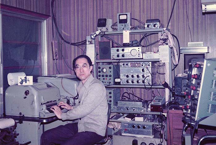
JA1DI - Isao Yamaguchi, Tokyo, Japan - RTTY QSL CARD & PHOTO - 1 MAR,1975
The good old days of Real Machine RTTY with shelves of homebrew gear, Kleinschimdt TTY machines, a Tektronix 535 oscilloscope in the foreground (and on a cart too) and, behind the 'scope, a USN RAO-7 receiver. JA1DI's actual QSL card is setting on top of the TTY machine. At the time, in 1975, Nevada was a rare state for DX stations and Nevada on RTTY was really rare.


Brief History of Radioteletype

In August of 1922, the U.S. Navy sent Radioteletype from an airplane setup to a ground receiving station. A couple of years later, RCA used RTTY to send messages from Chatham, Massachusetts to a ship at sea, the RMS Majestic. There was an early commercial RTTY station that sent traffic between San Francisco, California and Honolulu, Hawaii starting in April 1932. By 1934, San Francisco to New York City, NY was added. There was a tremendous growth in the use of RTTY during WWII because of its somewhat cryptic nature, even though the Baudot code was well-known (after all, it had been around since 1874.) However that didn't keep the messages themselves from being encrypted. Diversity RTTY was used by the military extensively after WWII to assure solid copy when propagation conditions were causing signals to fade in and out. The GRC-26 mobile hut contained all of the equipment necessary for mobile diversity RTTY communications at level of 350 watts of RF output power. In the GRC-26, the T-368 transmitter used one antenna while the dual R-390 receivers and the CV-116 diversity RTTY TU provided diversity reception using two other antennas. RTTY-type of communications used by the military today is quite different and is computer driven.

Amateur RTTY really got started after WWII when many of the hams were exposed to RTTY while in the military. As civilians, they found that the machines were pretty easy to find. Early amateur RTTY used mostly homebrew TUs and FSK modified ham transmitters. Some early ham setups employed the polar relay that was usually still installed in the machine when it was purchased at that time. Soon, amateur TUs were operating the selector magnets directly and the polar relay bypassed or removed. When good quality SSB transmitters became available, then AFSK signals could be fed into the audio input and FSK signals were easily produced. This made multi-band operational much easier than it had been when FSKing the transmitter VFO. By the late-seventies, simple computers and even simpler programs began to replace the actual machine driven RTTY. Within another decade or so, at least by the 1990s, it was difficult to find any ham on RTTY and those few that were operating RTTY used computers to emulate Baudot for both sending and receiving. Today, amateur RTTY contests are about the only time that moderate activity might be encountered.

Other info,...TTY is an abbreviation for Teletype. RATT was used in England and by the US Navy. It was an acronym for RAdioTeleType. The US Army Signal Corps used the term SCRT, an acronym for Single-Channel Radio Teletype.


Teletype Corporation, Kleinschmidt Laboratories, Morkrum Company and others - Brief History

Teleprinters go back to 1849 when a loop circuit between Philadelphia and New York City was started. The machines were crude and had many problems that seemed to delay any significant developments until about 1902. At that time, engineer Frank Pearne approached Joy Morton (Morton Salt Co.) with the idea of financing a mechanical reading and writing telegraph machine. Morton did supply the money and also brought in Charles Krum to assist in the development. Shortly after that (about one year) Frank Pearne left for a university teaching position, which left Krum working with Joy Morton's son, Sterling Morton.

By 1906, Morton and Krum formed the Morkrum Company to develop various types of teleprinter machines but any serious interest in large-scale usage by major companies wasn't happening. About this time, Charles Krum's son, Howard Krum, joined his father in the teleprinter business. In 1915, the Associated Press decided to try out a Morkrum machine and that seemed to be the turning point for the business. However, competition was now coming from Edward Kleinschmidt who had also been producing various types of teleprinters concurrent with Morkrum. Both companies had added a "start and stop" pulse to the code to actually have the teleprinters function correctly and, rather than spend endless time and money over courts and lawyers, Morkrum company merged with Kleinschmidt Corporation in 1925 becoming the Morkrum-Kleinschmidt Corporation. In 1928, that company name was shortened to Teletype Corporation. In 1930, AT&T bought Teletype Corp. for $30 million dollars in stock and placed Teletype Corporation as a division of AT&T's manufacturing subsidiary, Western Electric.

After the AT&T purchase, Kleinschmidt's agreements with Teletype Corporation expired (1931) and Kleinschmidt went back into the business of building their own teleprinters as Kleinschmidt Laboratories, Inc. During WWII, Kleinschmidt demonstrated a portable, 100wpm teleprinter machine to the Navy. The Navy ended up purchasing the machines which became a standard for the Navy (along with several varieties of Kleinschmidt and Teletype Corporation machines.) Kleinschmidt is still in business as Kleinschmidt Inc., doing business in electronic data exchange equipment.

Teletype Corporation operated with a slightly different business model in that they could sell directly to other companies outside of the Bell System, which eventually included sales to all branches of the military. From pre-WWII up into the late-1970s, Teletype machines were used in almost all business communications for most companies. Most business product ordering was by TELEX.

Teletype machines evolved over the years with several different codes tried but Baudot and then later ASCII were the main successful codes used. The most popular speed was 60wpm but 75wpm and 100wpm were also popular and, after about 1950, most Teletype machines had a three speed selector switch. Early machines were generally robust, heavy and usually fairly large. All early machines required routine maintenance to keep them running reliably. All wire TTY setups employed polar relays to assure low noise on the line and reduce printing and sending errors. Later machines, from the 1960s on, though smaller and lighter weight, used plastic gears and levers, and were generally not the indestructible behemoths of the 1940s (in many cases, the plastic hasn't aged well either, becoming brittle and breaking easily.) As computers became more and more powerful they were also being installed into much smaller, light weight packaging. The computers required almost no maintenance since they were virtually all electronic. By the 1980s, a Teletype machine for company communications was becoming unnecessary and ultimately undesirable. By 1990, Teletype Corporation was no longer in business.

There were three companies in the USA that built teleprinters,...Teletype Corporation, Kleinschmidt Laboratories and Mite Corporation. Overseas in England, Creed built teleprinters. In Germany, Seimens & Halske along with Lorenz built teleprinters. In Italy, Olivetti built teleprinters.


Teleprinter Machines

Teletype Corporation

Model 19 ASR - USN AN/FGC-9


I purchased this Model 19 machine from a company called RTTY Electronics in the California SF Bay Area back on May 14, 1974 - over 45 years ago. RTTY Electronics is still in business in El Sobrante, CA and its owner, Paul Cembura, has been rebuilding TTY machines since 1966. In 1974, Paul was rebuilding teleprinters in the basement of his house. What a basement,... full of different kinds of TTY machines and parts. He had a washing system that used solvent (kerosine) to degrease the printers and a metal wash tub basin to capture the run-off. It was an experience just to go there and see all of the machines in various states of assembly and disassembly.

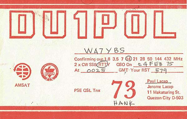
Needless to say, this Model 19 has always been in great condition - almost like new inside, probably because 45+ years ago, new parts were still easily available. I paid $125 for it and hauled it back up to Nevada in the bed of a 1969 Datsun pick-up (pulling Luther Summit was quite a load for the little 1200cc engine.) I used the machine actively on 20 meters from 1974 up to about 1980, working several DX RTTYers like DU1POL, Paul Lacap, who was the Chief of Police in Quezon City in the Philippine Islands (QSL card shown below,) or JA1DI, Isao Yamaguchi in Tokyo, Japan (see header photo above.) Up to about early-1975, I used a tri-band three element yagi for the antenna. An April heavy snow storm followed by high winds resulted in the complete collapse of the antenna and tower. After that, I used an extended (one and a quarter wave) inverted-vee wire antenna for 20M and my DX RTTY capabilities pretty much came to an end. Mid-1975 to 1980, many stateside RTTYers were worked with the Model 19 on the extended wire antenna.

At first I was using a homebrew vacuum tube type of TU. It was an updated W2PAT style that used miniature tubes but still used the TV width coils for the Mark and Space filters. After a while, I changed the filters to actually use the standard 88mH telephone toroid coils and the TU worked much better. Eventually, in 1977, I designed and built a new TU that used op-amp based active bandpass filters and an AGC op-amp input circuit. I used this all solid state homebrew TU from 1977 up to 1980.

In 1980, I moved from Gardnerville, Nevada to Minden, Nevada and didn't have any room for the RTTY station at the new QTH, so I stored the TTY from 1980 until 1993, when we moved to Virginia City, Nevada to open a "radio museum." In 1995, I serviced the machine, lubing and adjusting, in order to have it as a working exhibit in our radio museum. The only problem was I couldn't find any RTTY signals on 20 meters at that time,....at least 45.5 baud Baudot* signals (except for one lone XE1 station that was copied.) I assumed that real machine RTTY was dead.

In 2007, I again resurrected this Model 19. I had to replace the 323B grid-controlled thyratrons in the REC-30 loop supply in order to get the tape perforator working but otherwise the machine was still in fine operational condition. This time some 45.5 baud Baudot signals were copied but contests seemed to the only time there was RTTY activity. Although it was great to again RTTY being sent "on the air" I was pretty sure that the majority of contest ops were NOT on real TTY machines. I concluded that the ease of duplicating the Baudot code with a computer program for both sending and receiving was just too tempting for most hams when they were faced with the alternative of old, heavy, smelly, noisy, mechanically complex machines that did require routine maintenance and used a lot of paper (and even typewriter ribbons were getting harder to find.) For "Real Machine" enthusiasts, the incredible cacophony that accompanies the electro-mechanical operation of a TTY machine running "at speed" is a joy to hear. In fact, in the 1960s, the closing credits for the CBS evening news was accompanied by the sound of Teletype machines running in the background. Many radio news broadcasts still use the Teletype machine "sound effect" since it really was aurally synonymous with "THE NEWS" (although I guess that really depends on how old you are.)

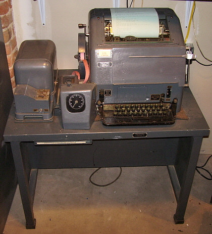
This Model 19 is the later version with the tape perforator counter mounted to the left of the keyboard inside the perforator housing. This mounting made the mechanism less likely to sustain damage compared to the earlier right side mount. The machine is military in origin and has holding magnets in the printer (connected in parallel for 60ma operation.) The USN designation was AN/FGC-9. The gray color is a later addition courtesy of RTTY Electronics.  The "ASR" indicates Automatic Send-Receive but all Model 19s are in this configuration so "Model 19" seems to cover it.   


photo above
: DU1POL, Paul Lacap, was the Chief of Police in Quezon City
 

Model 19 ASR with right side-mounted Tape Perforator Counter

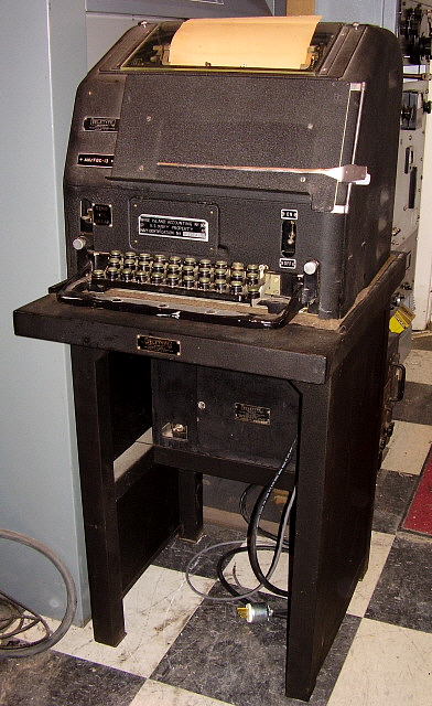
Shown in the photo Model 19 in black wrinkle finish. The machine was given to me by KB6SCO so that I could have an early style Model 19 for demonstration in the museum. The earlier style Model 19 machines have the perforator counter located on the right side of the machine.  This machine was functional and was operated on local loop. I'd put on a punched tape that demonstrated the machine for those museum visitors that were interested.

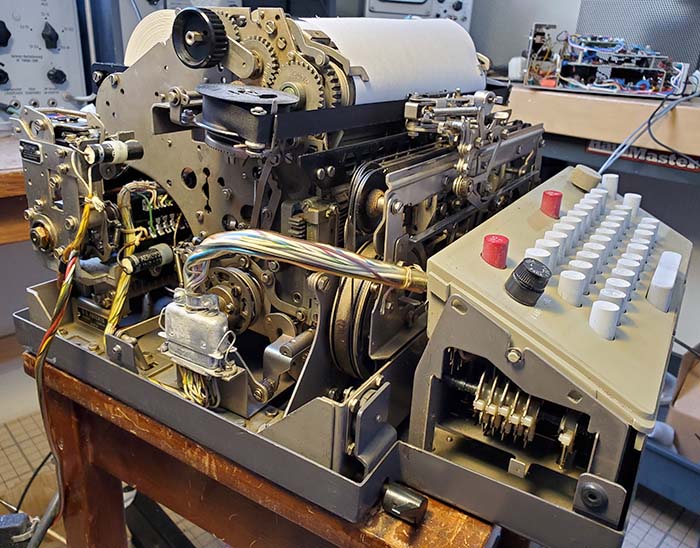
The Model 19 was introduced in 1940 and is essentially a Model 15 printer and keyboard in combination with a tape perforator set-up and a Model 14 Transmitter-Distributor for reading and sending the punched tape. The enormous and heavy loop power supply is mounted on a back shelf in the lower rear part of the table. There's a spring-loaded catch drawer for the punched tape chads located under the perforator. When set-up with separate KB/TD line and separate MAG line, it's possible to be receiving and printing a message while punching tape at the same time.

This Model 19 was by no means a perfect machine. It had several small problems. The tape reader didn't have the interlock pin that only allows operation when a tape is locked in the reader mechanism. I made a pin so the TD would work. The machine had been a Bell Systems machine that was originally sort of a greenish-grey wrinkle finish. It had been painted black over that original paint. This machine had pulling magnets, making it slightly different from my gray Model 19 that had holding magnets. The difference, though both were 60mA loop set-ups, was the DCR of the solenoids with the holding magnets being a much lower DCR and that did affect how the machine would operate depending on which TU was used. Since I was operating this Model 19 just on local loop, it didn't really matter but, if I had wanted to use it for "on the air" RTTY, I would've had to double-check which military TU I used. Some military TUs were intended for 20mA loops, some were intended just for holding magnets and were designed for the higher DCR of those types of solenoids. Anyway, since this Model 19 was just for demonstrations and ran on local loop, it didn't matter and it performed that function fine. I eventually gave the machine to an ham-enthusiast in Carson City around 2010. In 2021, KB6SCO bought this same machine back from the estate of the fellow I had given it to. John then gave this machine to fellow ham WA1ICI in Yerington, Nevada.
 

*Baudot is the name for the five level code used in earlier TTY machines (before about 1970.) It consists of a 33ms "start" pulse, five 22ms "code" pulses and a 22ms "stop" pulse. The code consists of a Mark or a Space, which generally is 1 for Mark or a high or a complete circuit and 0 for Space or a low or open circuit. Baudot was replaced by an eight level code called ASCII that allowed more characters to be generated for greater versatility. ASCII was developed in the early 1960s, published in 1963 and revised in the late-sixties, so most machines using ASCII are from 1970 or later.


Teletype Corporation

Model 28 KSR "Compact" - USN UGC-20

The Model 28 "Compact" is a M28 style printer combined with a M32 style keyboard all contained in a "skin tight" cover that reduces the size of this KSR machine to an absolute minimum. KSR is Keyboard Send-Receive and there were RO versions - Receive Only with no keyboard - the USN UGC-25, for example.

With a "footprint" of only 16" x 16" and a height of 10.5" it's pretty hard to get a much smaller "real machine TTY." Weight is also reduced substantially,...only 59 pounds. The printer has a speed selector lever on the lower left side next to the left side of the keyboard for 60WPM (45.5 baud,) 75WPM (50 baud) and 100WPM (75 baud.) The keys on this example are in very poor condition being extremely faded to almost white (they were gray originally.) This makes seeing the white key letter ID very difficult in normal room lighting. Some of the keys are cracked also,...but the KB does work, although at first its heavy action made it particularly difficult to get the "feel" and maintain the "rhythm" when typing (but this was later fixed with a thorough cleaning and adjustment of the keyboard.)

Of course, the extreme reduction in size didn't do anything to alleviate the noise generated by this little machine,...it still sounds like a full-size TTY machine when running and that's because there's no room for any sound-proofing in the ultra-tight fit cabinet. Additionally, there aren't any filters on any of the inputs or outputs. Two internal lamps (that run on a 6vac transformer in the housing) illuminate the paper for easy reading.
 

When used by the Navy, the M28 KSR Compact was given the designation of UGC-20. The Navy machines had a data plate mounted on the back of the cabinet. The turquoise color paint job on this machine, although looking almost convincingly original for quality, was probably left-over paint from someone's '57 Chevy restoration. Most of the M28 Compact machines seen in color photos seem to have been originally painted a business-like gray from Teletype Corporation. The TT Corp logo would have been located in the upper left corner of the front panel of the machine. From the date codes found inside, this machine looks like it was built in 1953.

Got the M28 Compact in January 2021. For a "blow by blow" account of getting this M28 Compact fully operational, go to "RTTY Projects" at the bottom of this page.
 

photo left: Showing the type box with protruding pins and the type hammer


photo above: The Model 28 KSR Compact isn't much larger than an IBM Selectric Typewriter. This M28 Compact sports a very non-original turquoise paint job. Machines were gray from Teletype. The front of the keyboard originally had a brushed-chrome decorative cover with "TELETYPE" embossed on it. The metalized sticker on the upper left of the panel was a former ham-owner's address label. It's been removed. The red rectangle at the right side is the "72 character" line end illuminated indicator. This machine was built in 1953.

photo above: The left side of the M28 Compact showing the knob in the base plate at the 90 degree bend is the "speed" control for setting 60wpm, 75wpm or 100wpm or 45.5 baud, 50 baud and 75 baud respectively. The plug hanging down towards the back goes into a receptacle in the cabinet for lights and other functions. The keyboard plug and receptacle connects the code bar information from the keyboard via wires (in the cable) to the Distributor at the left rear of the printer. The wired information allows the Distributor to energize the proper sequence of contacts in the Baudot code to transmit the selected letter. The Distributor runs off of the motor-driven gear box in the center of the printer. Yes, the chassis on the bench in the background (upper right) with the three levels of circuit boards is my old (1977) homebrew TU (it is connected up to the M28 Compact.) photo above: The right side of the M28 Compact showing the selector magnets (wires exiting the top.) In front of the selector magnet solenoids is the range finder/selector mechanism and below that the selector bars that place the type box in the correct position for the type hammer to strike the correct letter pin in the type box. In early Teletype machines, like the M19, the entire letter basket moves along with the setting of the selector bars allowing only one (the correct one) letter arm to move up and type. In a M28, the type hammer always strikes in the same place but the type box that contains all of the letters and figures moves its position (up or down, right or left) so the correct pin is hit which then prints the letter through the ink ribbon onto the paper. The metal cables pull the type box/type hammer mechanism along with the proper spacing between characters provided by the "toothed" spacing drum.
 

Teletype Corporation

M
odel 15 KSR - USN Mare Island Naval Shipyard

This Model 15 KSR machine, shown to the left, was owned by well-known Reno ham, Al Chin. Al worked on most of the radio gear for the Reno PD. He became an SK in the mid-1970s. I removed this Model 15 from Chin's backyard metal storage shed around 2003. It is in very good condition considering how it was stored. The metal tag on the front is a property asset tag and indicates that this machine was used at USN Mare Island Naval Shipyard located in the San Francisco Bay Area by Vallejo, California. This particular M15 uses a series-governed motor with strobe wheel.

The Model 15 is a KSR machine, that is, Keyboard Send-Receive. The indestructible Model 15 was introduced in 1930 and was ultimately found everywhere including radio stations, weather stations, police departments, newspapers.  Many times the keyboards were not needed in a "receive only" installation and there was blanking plate installed to cover the opening. Unbelievably, the Model 15 was produced up until 1963.    (Traded off in 7/2020)

Model 28 KSR - U.S. Navy

This Model 28 KSR TTY, shown to the right, was discovered by KB6SCO in a warehouse in Carson City, Nevada where it had been stored since 1997. It had apparently been purchased as part of a military surplus lot since the warehouse was literally filled with various kinds of equipment that had come from these kinds of "lot" purchases over several decades. When KB6SCO spotted the 28KSR, it had "TRASH" written in grease pencil on the lid and had various types of garbage inside. KB6SCO, knowing that I'm an avid TTY fan, obtained the TTY from the warehouse specifically for our museum. As can be seen in the photo, this 28KSR is now cleaned up and is in mint condition internally since it was never been put into service since it was rebuilt by San Diego Navelex in 1987. The Model 28 was introduced in 1951.

Now owned by KB6SCO who tells me this machine was set on 75wpm operation.

Model 28KSR


Teleprinter Machine Parts and Accessories

Polar Relays

Nearly all TTY machines that were actually operated on the wire telephone lines would be equipped with a polar relay. If the keyboard was connected directly to the line, then multiple problems would develop when the machine keyboard went to a Space which was usually an "open circuit." With nothing riding on the line, it was subject to many types of switching noise interference or various types of induced currents. The switching noise and induced currents caused many problems in accurate copy on the receiving end. The polar relay isolated the TTY machine from the line and allowed multiple operations and accurate copy.

The polar relay with the black cover is a Western Electric 215A polar relay and it is also shown in the photo to the right with its cover removed.

The polar relay with the gray cover is a Type 255A polar relay, manufacturer is probably Western Electric. It is also shown to the right with its cover removed.

For RTTY operations, most of the time, the polar relay is either removed or it is bypassed since the terminal unit is designed for a direct connection to the TTY selector magnets and the TTY keyboard.


Tuning Forks for Series-Governed Motors

Teletype machines that were used within the USA, and communicated with other USA-based machines, were equipped with synchronous AC motors that were designed to operate on 60hz line frequency which then had all of the motor-driven parts of the machine "timed" for this motor speed operation which worked out to be 368 operations per minute (45.45 baud.) During WWII, communications between the USA and England required some machine adjustment since England used 404 operations per minute as their standard (50 baud.) To have compatibility, TTY machines that were sent overseas (or were in the USA but setup to communicate with England) were equipped with series-governed AC motors. The series-governed motors could have their speed adjusted so that, when in mutual communications, the machines would run at 404 o.p.m. This was called "Military-Allied Interoperation" and had the machines running at 67.33wpm or 50 baud. These series-governed motors had a strobe wheel mounted to the back of the motor shaft. When adjusting the motor speed for Military Allied Interoperation, the technician would turn on the machine and let it run for several minutes. Then he would strike the tuning fork against something to start it vibrating. Then the strobe wheel would be observed through the slit at the end of the fork. The motor speed adjustment was moved until the strobe pattern was stationary. This would have the machine set for 50 baud. The fork actually used for 404 o.p.m. was marked "British Speed 404.0 O.P.M." and the fork vibrated at 96.19 v.p.s. The fork shown in the photo is for setting a series-governed motor to 368.0 o.p.m or 60wpm (45.45 baud) for communications with other 60wpm machines or returning a machine to 60wpm after performing communication duty at 50 baud. This fork vibrates at 87.6 v.p.s. (vibrations per second).

The smaller fork is a Kleinschmidt Labs, Inc. fork for the same purpose but it vibrates at 180 v.p.s. This fork was for the higher speed machines that Kleinschmidt made for the Navy that operated at 100 wpm.


RTTY FSK Converters/Terminal Units


Vacuum Tube RTTY FSK Converters/Terminal Units


the Hallicrafters Inc.

U.S. Army Signal Corps  -  CV-31D/TRA-7

The CV-31 Series of RTTY Converters were for dual diversity set-ups to assure the most accurate copy for military RTTY uses. Diversity reception compensates for fading radio signals and provides a constant level signal to a data converting device such as a RTTY Converter and TTY machine. Many different types of receivers were used with the CV-31 Converters. There are photos showing the CV-31 used in the early GRC-26 Mobile RTTY set-up using modified BC-342 (designated as R-336) receivers. Other applications used Hammarlund BC-794 (R-270/FRR designation) receivers as the dual diversity FRR-12 which was used with a rack mount version of the CV-31. There were several other configurations using other types of receivers. The IF output from the two receivers is used as the signal source to the two channels of the CV-31 (Ch. A and Ch. B.) The front panel vernier tuning on the CV-31 allows some adjustment for the various IFs encountered.

A typical commercial-military dual diversity set-up usually required two widely spaced antennas with 1000 feet of separation usually specified. However, the GRC-26 specified 600 to 900 feet and many times a useable diversity effect can be obtained with antenna separation that is as little as one wavelength at the received frequency. In some dual diversity receiver set-ups, the receivers are tied together at the AVC and at the Diode Load to provide diversity action within the receiver circuitry. Usually, for military RTTY installations, the IF outputs from the receivers are fed directly to a RTTY converter and the diversity combining is accomplished within the RTTY converter circuitry. The diversity combining is done in the CV-31.

The CV-31 series was introduced at the end of WWII and was in active use well into the 1950s. This CV-31D/TRA-7 is from a 1951 contract. 25 tubes are employed and the weight is in excess of 100 lbs.   (Traded off 7/2020)


Hoffman Laboratories, Inc.

U.S. Army Signal Corps  -  CV-116/URR

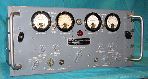
The CV-116 is a dual diversity RTTY FSK TU that was designed for the Signal Corps to be used with two R-390 receivers for space or frequency diversity RTTY primarily within the GRC-26 mobile communications hut. Using 45 tubes and weighing in at nearly 70 lbs., the CV-116 uses the 455kc IF output from two R-390 receivers for its signal input to each channel. The input stages are similar to a receiver's input in that an RF amplifier, oscillator and mixer are used in each channel. Channel A operates at 50kc and Channel B operates at 29.3kc into their respective discriminators. Although crystal control can be used, AFC is also available to compensate for receiver (or signal) drifting. There are two, motor driven AFC controls that use amplifier circuits in feedback loops to drive motors that gear drive a tuning condenser that keeps the oscillator tuned for each channel. The red lamp is an addition that provides a visual alarm indication that the driven AFC condensers are near the end of travel. Normally, the internal bell gave a warning alarm but if several CV-116s were in use with several TTY machines, it would have been difficult to find which CV-116 was giving the bell alarm, thus this addition which provides both alarms. The second from the left meter (M4) can be switched to monitor several areas of the circuit including the built-in, adjustable loop supply. The CV-116 is designed to drive the TTY printer magnets directly (cable interface required) and will drive resistive loads from 125 to 500 ohms. This Cadillac of military TUs was built in 1953. It was fully functional and used with a R-390A receiver to copy RTTY on the Model 19 TTY. I actually had two of these monster TUs.   (Traded off both units 7/2020)


U.S. Navy  -  CV-57/URR

The CV-57/URR was a component of the dual diversity RTTY system designated AN/URA-6. Two CV-57s and a Comparator designated as DM-14 comprised the system. The CV-57 used the IF output from compatible receivers, such as the RBB, RBC or RDM. However, the actual range of IF inputs was from 395kc up to 470kc, so it was possible to use a 455kc IF rather than the 400kc IF of the RBB/RBC receivers. The circuit uses a series of selectable filter center frequencies and the incoming FSK signal is tuned to allow the mark and space frequencies to straddle the center filter frequency. The system could operate up to 100wpm RTTY. From the early 1950s.  (Traded off 7/2020)


Hoffman Laboratories, Inc.

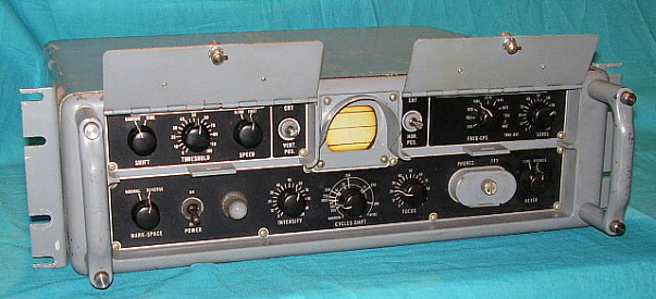
U.S. Navy  -   CV-89A/URA-8A

The CV-89A was part of the AN/URA-8 diversity RTTY system that was built for the Navy by Hoffman Laboratories, Inc. Two CV-89A units were used with a combiner unit to achieve space diversity and reduce fading signals to improve RTTY copy accuracy. Using 15 tubes, the CV-89A is modular in construction. Five modules make up the unit - four are mounted in the chassis and one is mounted in the back of the case. Being an audio discriminator device, the operator has to tune the RTTY signal so the mark and space frequencies straddle the center frequency of the filter selected. Narrow shift center frequency is 1000hz and wide shift is 2000hz. The CV-89A features a built-in oscilloscope display to aid in tuning and determining FSK shift. The oscilloscope display will shift vertical positions with mark and space frequencies and by adjusting the shift knob so the display spreads between the three graduations on the display scale, frequency shift can be measured.

The CV-89A requires a separate loop supply in series with the printer magnets, or the TTY machine can be wired KB, MAG and LOOP in series then the CV-89A will "key" the entire loop and operate the printer. The MAG line and loop supply can be connected to the rear A/N MIL connector (14S-9P) or if the TTY/loop is set-up with a single .25" phone plug, it can be inserted into the jack on the front panel behind the small door in the lower right panel. An excellent, easy to use military TU. Built in 1953, this CV-89A was fully functional and provided great copy with any receiver that had a 600 audio line out.

One note,...internally the CV-89A keying circuit assumes that the selector magnets are going to be connected for a 60mA loop for pulling magnets. My Model 19 selector magnets were holding magnets connected for a 60mA loop resulting in a lower DCR. The CV-89A circuit uses a 30K 2W CC resistor in the circuit. In order to get the keying circuit to work with my Model 19 holding magnets and a 60mA loop, I had to change the 30K to a 10K 2W CC resistor. The CV-116 TU also required this change to operate with parallel connected holding magnets.

I traded off the CV-89A shown above in July 2020 - BUT, I've now acquired another CV-89A SN: 5449, shown in the photo to the right. I know, it looks just about the same as the one I formerly owned. But, I did take this photo with the two lift-up covers closed showing typically how the CV-89A looked when in operation. In 2007, I went though this very same CV-89A for KØDWC to get it operating correctly and that's who I've gotten it from (in a trade.) This one will be used for testing and experimenting on how to convert ITTY's standard Mark and Space tones to different frequencies that will work with other types of audio frequency TUs, especially military TUs,...CV-89A or the Northern Electric Type 153 Model 2, for example. More details as the experimenting gets going.   Mar 2021.


CV-89A SN: 5449 from 1953


I may be getting another one of these soon,...it seems nobody can figure out what to do with them but they are just too nice to junk! I'm supposed to also get complete documentation with this next Type 153 which may help in determining the ultimate usability of these TUs.

Northern Radio Company

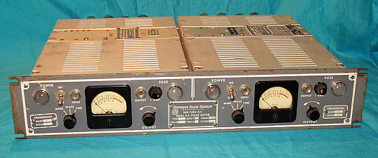
Type 153 Model 2

This is an Audio Tone Frequency Shift Keyer built by Northern Radio Company. It's a dual channel unit and both units are completely independent of each other. Fixed tuned filters are used and are set for 85 Hz shift. Generally, the 85hz shift is used in stations that were operating on LF or VLF. This was due to the increased affect that the shift frequency had in relation to the general operating frequency at those lower frequencies. For example, at 100kc, a shift of 850hz will require a 100.00kc and 100.85kc RF frequencies for Mark and Space, which is almost a 1% frequency change at 100kc. At lower frequencies, the affect increases dramatically. This can cause problems in transmitter tuning and in antenna resonance at LF and VLF operating frequencies. The Type 153 also employs non-standard tones filters with a Mark frequency that is higher than the Space frequency. It has been reported that the government State Department used the Type 153 in their RTTY feeds to the VOA stations. 12 tubes total are used, six in each unit. I've never used this TU since it is such an odd, apparently special function unit. Mid-fifties vintage. Unbelievably, another one of these Type 153 Model 2 TUs made it into the collection in 2019.    (Traded off both units 7/2020)  Note: June 17, 2021 -  I found an original NE Type 153 Model 2 manual and it indicates that the use of the TU was for VHF operations,...oh,...and I never did get that donation of the Type 153 mentioned about half a year ago. 


Solid State RTTY FSK Converters/Terminal Units


Dovetron

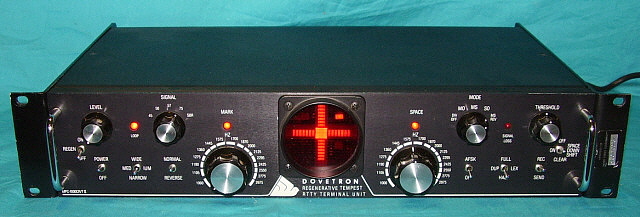
MPC-1000CR/T  "Regenerative Tempest"  MIL-SPEC RTTY TU

Possibly the most electronically elaborate RTTY TU ever built for use with real machines. Though the Dovetron "Tempest" looks very similar to the civilian MPC-1000RC (below), it is the military/government version of the TU and MIL-SPEC is used throughout the unit. The Tempest units will have BNC connectors for inputs and outputs on the rear and a 14S-7P power input connector. Speed conversion, diversity capability, duplex afsk and tunable mark and space filters are the standard features but the Tempest versions do not have an auto-start feature or the keyed TTY loop supply of the civilian models. FSK polar outputs are provided to drive a loop keyer for machine RTTY or whatever else you might want to use. Both +/-6vdc and +/-12vdc FSK polar outputs are provided. The MPC-1000CR/T shown is in the "self-test" mode to show the SSD "Cross-fire" LED display operating. The horizontal line indicates mark and the vertical line indicates space. A fantastic TU that really has the great performance to go along with its great looks. Built in the early 1980s.     (Traded off 7/2020)

At the N7RCA Minden Swap Meet on June 5, 2021, KB6SCO and WA1ICI had two Model 15 TTY machines running printing out ITTY as a demo. KB6SCO was using this same MPC-1000CR/T Tempest to interface ITTY with the two TTY machines. The Tempest worked flawlessly. A really nice demo that had more than the usual level of interest. One M15 had the cover off to show the printer in action.


Dovetron

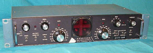
 MPC-1000RC - Multipath Diversity RTTY TU

The MPC-1000RC is a commercial/civilian RTTY TU that can do speed conversion, multipath correction, auto-start, AFSK and has a multitude of other abilities depending on the users requirements and the TU's options. The MPC-1000RC features front panel tunable filters for Mark and Space from which shift can be determined. Originally, the early Dovetrons used a CRT display but later a SSD "Cross-fire" LED display could be installed to replace the CRT. The Dovetron shown has the LED "Cross-fire" display replacement option installed. Mostly op-amp technology but a considerable amount of digital CMOS in the UART board which does the speed conversions. The MPC-1000RC provides an adjustable built-in loop supply to directly drive the printer magnets. Built in 1976.      (Traded off 7/2020)    


Do all ST-5s Look Like This One?
 

HAL Communications Co. - PEMCO

ST-5 with modifications

The ST-5 was one of the first TU's to use op-amp technology utilizing the 709C op amp. It came out around 1970 and seems to have started out as a homebrew project write-up that then evolved into a parts kit that contained most of the components needed to build the TU. This ST-5 has a couple of PC boards that are marked "Pemco" as the supplier but I don't know if that's just for the PC boards or for the entire parts kit. The TU circuit uses toroid based filters, limiter, detectors and a built-in loop supply that is keyed for direct connection to the printer magnets. The initial ST-5 was just a basic TU only providing the necessary functions for receiving RTTY. Later, there were upgrades available for AFSK and Autostart but I'm not sure what company provided these upgrades.

I took a closer look at this TU and besides the ST-5 PC board, there are four other PC boards inside the cabinet. One PC board is an AFSK oscillator. One PC board is for Autostart. One is a power supply board. One small board mounted on the TU board has "ST-5 Upgrade" on it. The entire build-job inside looks like the absolute worst "hamster" work and, although the front panel looks very nice, the rear panel is terrible with masking tape IDs on a non-symmetrical layout of switches. Luckily, the ST-5 basic TU is documented fairly well, but the upgrades in this particular example aren't marked as HAL boards (Pemco is the ID on two boards) and some of the boards may have been after-market suppliers or homebrew additions (one board has ham call letters in etched trace copper.) To get this TU operation and would require a complete "gut job" and then rebuild it competently.    


HAL Communications Co.
ST-6

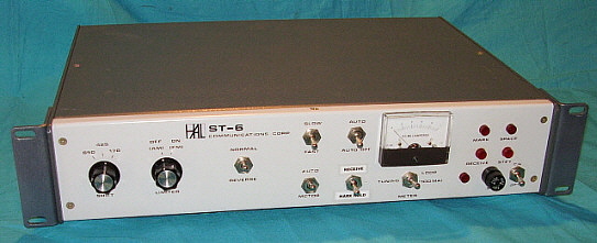
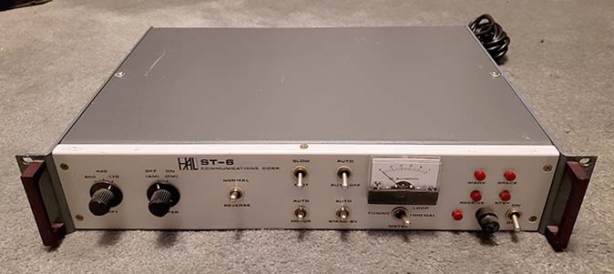
The old stand-by,...the reliable ST-6 was (and is) the work horse for real machine RTTY. Using toroid based filters and op-amp technology, the HAL ST-6 is easy to operate and it is easy to tune in stations. All ST-6 TUs have AFSK capability to allow T-R RTTY using just the ST-6. The circuit is comprised of eight PC boards that plug into sockets that are mounted vertically. The power supplies are chassis mounted components. Early versions of the ST-6 use .25" phone jacks for TTY outputs and RCA phono jacks for inputs. The later versions will have Molex connectors for the TTY outputs. If you do have to work on the ST-6, it's well laid out making it easy to troubleshoot and repair. Too bad it doesn't have the "Dovetron" looks. Actually, the ST-6000 layout is much better and is similar to the "Dovetron looks" with a center-mounted CRT.               (Traded off this ST-6, 7/2020)

The ST-6 is a great RTTY TU. Its technology uses mainly discrete components in one sense but since op amps are employed for each of the TU active circuit functions it could be also thought of as an early integrated circuit type of TU, even though the passive LC Mark-Space filters using toroid inductors are also part of the component inventory. This early use of op-amps makes the ST-6 functions very easy to understand and very easy to troubleshoot when a problem "crops up" even though that seldom happens.

NOTE: June 2022 - I'd traded off my original ST-6 almost two years ago but now another ST-6 has made it here (a donation.) This ST-6 is the later version with the Molex connectors for the TTY outputs, different knobs, different red lamp lenses and the meter is illuminated. Apparently when this ST-6 was built no PC board bracket retainers were used and the retention of the PC boards in their sockets depended on the spring tension of the socket's receptor contacts. This worked okay for some of the PC boards but the three filter boards, with their large and heavy toroid coils, had too much weight and with rough handling (shipping?) these PC boards were able to move laterally and crack the sockets. This greatly reduced the ability of the socket to "grip" the PC board. When I got this ST-6, the 170hz shift filter board was "rattling around" inside the cabinet. An inspection revealed that all three filter board sockets were cracked. If the ST-6 doesn't have the PC board bracket retainers, then it has to be handled carefully. This wasn't a problem when the builder knew his unit and it was installed into the RTTY station and wasn't going to be ever be roughly handled. But, subsequent owners may not have even looked inside these ST-6 TUs and shipping a ST-6 that doesn't have the PC board brackets across the country is certain to cause some problems. Although this ST-6 works fine, because of the socket cracking, I had to add bracket-retainers to the filter boards to keep them tight in their sockets.

I know,...you've seen one ST-6,...you've seen them all,...right?   This one is #2


HAL ST-6000

HAL Communications Co.
ST-6000


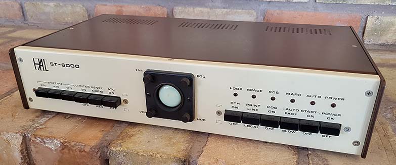
The ST-6000 continued the evolution of RTTY TUs from HAL Communications Company. The ST-6000 is mostly digital circuitry and uses an AGC input circuit proceeding two active filters for Mark and Space audio tone frequencies. There were two Tone Frequency options available, "Low Tone" that used 1275hz for the Mark tone and "High Tone" that used the RTTY standard 2125hz Mark tone. There was a stick-on label on the back panel that indicated which Tone option was installed. Unfortunately, it isn't an easily switchable option and requires component changes within the active filters and the AFSK circuit. Three frequency shifts were selectable, 850hz (former military standard,) 425hz (commercial SW users) and 170hz (ham and many other users.) The CRT provided a "crossed-ellipse" pattern to monitor Mark and Space tuning and when receiving RTTY at speed. At 850hz shift the ellipses are very narrow but at 170hz shift the ellipses widen somewhat. The four small knobs at each corner of the CRT bezel are the adjustments for the 'scope, e.g., Intensity, Focus, Horizontal and Vertical position. Other features are KOS (Keyboard Operated Switch) that allowed a PTT line to be operated by TTY keyboard. ATC is Automatic Threshold Correction which corrects bias distortion that is caused by propagation conditions. Also, DTA which is Decision Threshold Hysteresis corrects for multipath propagation conditions that cause phase distortion by slightly delaying keying until a positive "switching" between Mark or Space has occurred.  

Autostart for machine operation start up, print and shutdown, automatically. Autostart would detect if a RTTY signal was being received and turn on the TTY machine. When the signal stopped the TTY machine would turn off (machine powered by the AC outlet on the rear panel) after a short delay. Small LEDs provided various indications as labeled. MOLEX connectors were used on the rear panel for all connections to the ST-6000. An internal 60mA loop supply was provided (along with other keying options.) The AFSK output level was adjustable internally and the tones generated were fixed and matched the tones that the ST-6000 active filters were set to.

When originally purchased, the ST-6000 came with pre-manufactured cables for all inputs and outputs. Why HAL decided to go with MOLEX connectors is a mystery. At the time, they were the "latest and greatest," but today, while finding the pins and shells isn't difficult at all, the proper crimper is an expensive tool that is commonly and erroneously considered a necessity for proper connector/pin to shell assembly. Through experimentation I've found that the crimper isn't necessary at all. With careful use of a pair of needle-nose pliers, the two sets of metal tabs can be bent as necessary to crimp the wire and the insulation. Then the wire is soldered to the Molex pin just in front of the crimp. There's a slight "well" at that point for the solder application. If carefully done, the Molex pin will fit into the shell with no problems.


photo above: The rear connections to and from the ST-6000. This version is housed in the "fancy" enclosure that was brown faux grained covers with cream colored panels (apparently popular in the 1970s - the WA7YBS HB TU also had this faux grain treatment on its panels.) The ST-6000 was also available in a standard two-tone gray-cream table version and a gray-cream rack mount version.
 

Flesher Corp.

Model TU-170

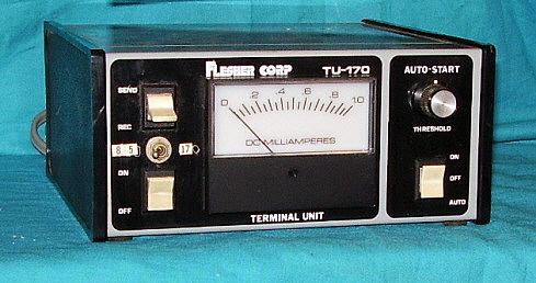
This small TU is mostly op-amp technology although there are four discrete transistors also in the circuit. There aren't any toriods so I assume that the TU-170 uses active filters for Mark and Space circuits. It has a built-in loop supply and also has auto-start capabilities. The plastic and metal case is very small for the amount of circuitry inside. Dates from the mid-1970s. I've never attempted to get one of these Flesher TU-170s operational, so how well they work is an unknown. Also, from the "mod" that apparently allows selecting 850hz shift or 170hz shift, I'd guess that the TU-170 only did 170hz shift originally. The TU-170 has a NE-555 timer IC on the PC board (AFSK or AutoStart timer?) There is a connection on the back that allows connecting the TU-170 to a transmitter which implies that it does have AFSK ability (adjustments must be some of the pots on the circuit board inside.) I had two these little TUs. When I traded KB6SCO most of the RTTY gear, one of the TU-170s "escaped" the trade-off and was later found hiding in a junk box. Later, I asked John if he wanted this other TU-170 too but he declined,...I wonder why?


Electronics International Service Corp. (EISC)

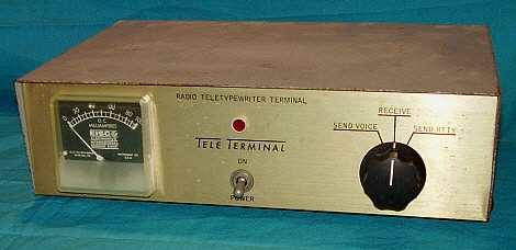
Model TV1-C  "TELE TERMINAL"

This TU is a basic unit that provides only TTY decoding with a built-in loop supply. Discrete transistor technology and toroid based filters make this a very simple unit to work on. Normally the AFSK oscillator output would be connected to the microphone input of a SSB transmitter which resulted in FSK signals - at least that was how it was done in the seventies. This TU provided a mic input on the back and then the operator could select RTTY or Voice from the switch and not have to disconnect cables. The TU itself does not have AFSK capabilites. The meter is dated February 1971.     (Traded off 7/2020)


1977 WA7YBS Homebrew RTTY TU

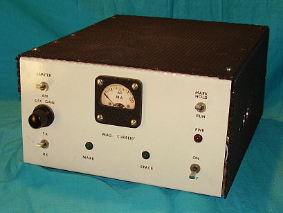
WA7YBS Home-designed and brewed RTTY TU - 1977

I designed and built this op-amp based TU in 1977. I decided to use active bandpass filters as they were the current "buzz word" at the time. Unfortunately, active bandpass filters require a sine wave input and the square wave output of a standard RTTY TU limiter wouldn't work correctly. I ended up using an op-amp based AGC IC (LM-370) for the input so the filters would always "see" a sine wave regardless of the input signal level. At first I had the Q so high on the active bandpass filters that tuning in a signal was next to impossible (Q was 40.) The filter bandwidths have to somewhat overlap at the center (about 2210hz) for ease of tuning and good copy and this was accomplished with a lower Q in each of the bandpass filters (RC component change to have the Q at 10 worked fine.) I used a different type of op amp, LM-301 instead of 709C types. Using the green LEDs for Mark and Space indicators was an idea that worked just "okay." You can barely see the Space LED switch on. It was a limitation of the LED technology at that time,...especially green LEDs. The "AM - LIMITER" switch is left over from the limiter circuit used before going to the LM-370 AGC circuit (switch is non-functional now.)

My AFSK circuit used an Intel 8038CC "Function Generator on a Chip" (you used to be able to get them from PolyPacks,... remember them?) I switched between two fixed 1% MF resistors using a DG-200 "low resistance -on- analog switch" that was controlled with a 4049 quad buffer/inverter (I only needed two inverters in series to obtain opposite switching for Mark or Space resistances.) Surprisingly, this AFSK system worked quite well. For local copy, I took the AFSK output through a LM-301 buffer to also drive the input of the TU (TU input was switched to the AFSK buffer output during transmit only.) This resulted in an actual received copy on the printer instead of local copy from the KB breaking the local loop.

I had my Model 19 with the KB on a separate line from the MAG line rather than having the KB/MAG in series for local loop copy. It all worked pretty well and I used this TU from 1977 until 1980. Built in a cheap-o, late-seventies project box with the creamy-white gloss paint job. I changed the original stick-on faux wood-grain vinyl covered top to this black purf-metal cover almost immediately. How about that rub-on lettering? All typical of homebrew construction, at that time. Using an oxymoron,...it's pretty ugly. Oh,...you want a look inside?    

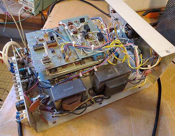
The photo to the right shows the inside of the homebrew TU. Kinda looks homebrew too, doesn't it? Well,...I was only 27 when I designed and built this TU,...and it does still function (after a little re-familiarizing on my part and a switching transistor replacement.) The upper circuit board to the left is the AFSK board with the Intel 8038CC "Function Generator on a Chip" and the DG-200 analog switch. The round metal can IC in the socket at the lower left corner of the board is the DG-200. The two pots are compensation adjustments for the 8038CC output waveform distortion. The upper circuit board to the right is the LM-370 AGC input circuit. The other two op amps (LM-301) are two gain stages following the LM-370. The pot on this circuit board adjusts the AGC threshold. The lower board contains the active bandpass filters using four LM-301 op amps (two for each filter,) detectors (germanium glass diodes,) LP filter and comparator circuits (three LM-301 op amps and germanium glass diodes.) The HEP S-5015 (now a EGC157) switching transistor is mounted on the metal case floor. The smaller transformer is for the +/-12vdc supply. I originally used active regulation via a LM-340-12K for the positive and a LM-320-12K for the negative but apparently I had trouble with these 1 amp-rated regulators. I don't really remember why but, sometime before 1980, I decided to simplify the supplies and removed the active regulators and installed zener regulation for both positive and negative 12 volts dc instead. The larger transformer (all metal covering) is for the loop supply in which the negative is elevated above chassis ground using a 2.7K 20W resistor. There are four "vector prototype board constructed" circuit boards used, the AGC bd., the TU bd., the LED/xsistor bd. and the AFSK bd. The power supplies are built onto the floor of the project box. The WA7YBS TU is a good example of late-1970s homebrew design thinking about how to do Real Machine RTTY using mostly then-modern components and technology. So, when looking at this TU nowadays, no doubt I would do a lot of things differently both in design and certainly in construction. But, the main thing is,...it does function and it does provide good RTTY copy,...even if it is a little dated and "amateurish." And, after all,...it is "amateur radio" isn't it?


RTTY Station WA7YBS in Virginia City, Nevada (2007-2010)


The photo to the left is of my old RTTY station that I had set up in the basement of my Virginia City, Nevada QTH in 2007. I had the RTTY station set up for about two years and only contacted one other "Real Machine RTTY" station for a two-way sked (and he was in the same town, Virginia City!) I had a standing invitation on this website (in this RTTY section) for any ham wanting to set up a sked to try a two-way Real Machine RTTY contact. I only received one e-mail in that length of time. The fellow wanted me to send some "Real Machine RTTY" to him over the air so he could "hear what machine-sent RTTY sounded like!" Hmmm. That didn't happen, of course.

By 2010, I needed the space in the basement and, since there had been virtually no interest in "on the air" Real Machine RTTY, the station was taken down and most of the RTTY gear put into storage.

The station equipment was as follows, center floor is the AN/FGC-9 (Model 19) TTY machine and to its right is the Collins KWS-1 transmitter. The KWS-1 provided a very easy method of sending RTTY over the air. An AFSK oscillator is fed into the Microphone input. Since the transmitter suppresses the carrier, eliminates one sideband and then the transmitter's IF converts these two audio frequencies to RF and those are then amplified by the internal linear amplifier, the resultant output is two alternating RF frequencies separated by 170hz. It doesn't matter what band you use, the shift always remains the same. A very easy way to do FSK. This is the same KWS-1 SN:616 that I used in the late-seventies for RTTY on 20M (I've owned it since 1970.)

On the shelf left to right, Dual Speaker Panel on top of a HAL ST-6 RTTY TU. The ST-6 was a great TU that always seemed to function reliably after I went though it and changed a few things to better operate with my particular setup. The Collins 51J-2 receiver is a fabulous general coverage receiver. It predates the famous R-388/URR but is still a very good performer. Next to the J-2 is the well-known Collins 75A-4 receiver. The 75A-4 provides excellent stability and sharp selectivity needed for RTTY. This is the same 75A-4 SN:875 that I used in the late-seventies for RTTY on the air QSOs on 20 meters.

The setup used the 75A-4 and KWS-1 as the receiver and transmitter and then demodulated the RTTY with the HAL ST-6. This setup with the Model 19 TTY worked quite well. The Collins KWS-1 was run at reduced power due to the 100% duty-cycle of RTTY but still 150W output provided a decent signal.


In the photograph foreground left side is the military RTTY TU equipment rack (a Brush Industries rack.) More about the rack below,...

The photo to the right shows the military RTTY TU equipment rack. In the rack from top to bottom, USN CV-89A RTTY TU, Dovetron Tempest RTTY TU, Signal Corps CV-116/URR RTTY Diversity TU, Collins R-390A/URR receiver, Dovetron Multipath RTTY TU, Patch Panel, Keying Loop Supply and at the bottom an 6" PM speaker with 600 ohm Z matching transformer. All of the gear in the rack does work.

Although this station is no longer set-up, I still have all of the gear shown (well,...most of it.) With our 2012 move to Dayton, Nevada, I now have ample space for a RTTY station in the shop, so it's just a matter of time before I have something set up and running real machine RTTY.

Well,...that's what I thought in 2012. Now, seven years later, the TTY machines are still out in the shop and the KWS-1 transmitter is upstairs in the ham shack.
 

Update July 2020 - I traded off most of my RTTY gear to KB6SCO. I still have ALL of the "radio gear" shown in these photos plus I kept the gray Model 19 TTY machine and the beautiful Brush Industries rack. But, all of the TUs in the rack and the HAL ST-6 are gone.
 

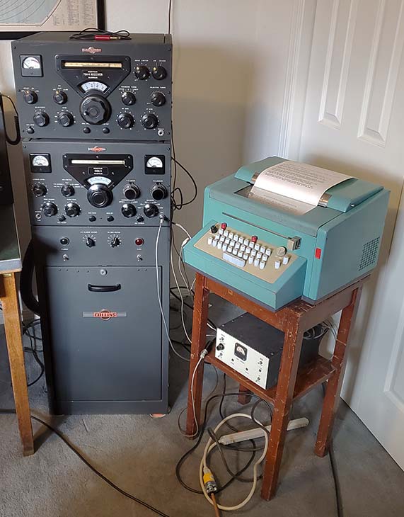
Update Feb 2021: Wouldn't you know it? After I traded off most of my RTTY gear, six months later I'm back interested in RTTY again because of the acquisition of the M28 Compact. At only 59 pounds and a 16"x16" foot print, the Compact brings the real possibility of actually running Real Machine RTTY in the house and upstairs where the ham station is located. This puts the M28 Compact running with my homebrew RTTY TU and using the KWS-1 and 75A-4 combo for transmit-receive. The 75A-4 is not the same one I used in 1974-1980 or in 2007-2010. Though I still have that earlier 75A-4, I did find a later version (SN:4470) in 1995 and that's the receiver I now use.  More info in "WA7YBS Homebrew TU" and in "RTTY Projects" sections at the bottom of this page,...also a photo of the current "WA7YBS RTTY station for 2021."
 

In the next section is a write-up and link to Internet-TTY that provides a 24/7 standard AFSK RTTY tones at 45 baud Baudot to run your TU and your real-machine TTY. An easy way to demo and use your machines receiving news feeds and similar type messages. Autostart also provided. ITTY is invaluable for testing and adjusting Real Machine TTY.


WA7YBS RTTY Station - 2007 in
Virginia City, Nevada


Internet-TTY

TTY enthusiasts finally have a source of 24 hours a day, 7 days a week AFSK TTY sent over the Internet. This site provides 45.5 baud Baudot, 170Hz shift AFSK standard tones as an audio signal that can be accessed from the earphone jack on any Internet capable device,...laptop, smart phone, tablet, computer,...as long as there is an audio output source available then that device can be used. The audio from the earphone jack is routed via a cable to your TU input and then the TU can operate your TTY machine printer. You should be able to use the ITTY signal directly - if your TU filters are set for the standard audio frequency of 2125hz for Mark and a 170hz up shift for Space. Also, Carriage Return, Line Feed, Letters and Figures are used within the text for correct operation with real machine teleprinters.

TUs designed for ham operation like the standard HAL ST-6 or ST-6000 will work fine. Most ham RTTY TUs have 170hz shift capability and use either active filters or even toroid based filters that are normally set up for 2125hz Mark and 2295hz Space and they will work fine with ITTY. I did see a ST-6000 one time that was set up for 1275hz Mark for some reason (computer RTTY interface most likely.) Usually there's a sticker on the back of the ST-6000 unit that indicates the Mark frequency that the filters are designed for.

If your TU uses non-standard Mark and Space filters or, perhaps is a vintage military type, whether or not you can use ITTY will depend on the particular TU. The Dovetron Tempest and most of the other Dovetron models will have adjustable Mark and Space filter frequencies so it's no problem to set up Dovetrons to work with ITTY. Many of the other military TUs use the IF output from a radio receiver as the input RTTY signal (approximately 455kc input, usually.) Some military or commercial TUs use odd frequency filters or odd shifts (like the Northern Electric Type 153.) The CV-89A audio discriminator type of TU has to have the AFSK signal "straddle" a selected center frequency with the Mark frequency below center and the Space frequency above center. The CV-89A has two center frequency options, 1000hz in NARROW and 2000hz in WIDE. The ITTY Mark frequency is 2125hz, which is just a little high for WIDE. Also, WIDE is for "wide shifts" (>200hz) so the 170hz shift on ITTY won't be sufficient since ITTY Mark frequency is also higher by 125hz. When the FSK signal was coming from a radio receiver tuned to a transmitted RTTY signal then the receiver's output tone audio frequencies to the CV-89A could be adjusted easily by tuning the receiver to produce the correct AFSK tones that would work with the CV-89A. But, the ITTY the frequencies are fixed at 2125hz Mark and 2295hz Space so an adjustable AFSK Tone Converter would be required for the CV-89A (or other military audio discriminator type TUs) to would work with ITTY (I've just acquired another CV-89A - Mar 7, 2021 - and will test and experiment on its possibilities for use on ITTY.)

The ITTY data sent is mostly comprised of "news feeds" and other types of material. You can upload information to Internet-TTY also. There's also Auto Start capability in some sections that allow your machine to start up and print copy and then shut down. So, now there is an easy way to have your TTY machine and TU actually operate easily. You don't have to wait for a ham RTTY contest for activity (in which none of the participants are using machine RTTY anyway.) For testing purposes, ITTY is invaluable. ITTY is on the "QRM-free" Internet 24-7. Here's the URL:  http://rtty.com/itty/index.htm  

Thanks to John Lawson KB6SCO for repeatedly telling me about Internet-TTY until I finally listened and started using it.
 

Connecting to ITTY - I used a Samsung SM-T580 (Tab A 10.1) tablet as my browser and used a 3.5mm stereo phone plug with 6ft cable to connect the audio from the tablet to my homebrew TU. The audio cable originally had phone plugs on each end but I removed the plug from one end so I could attach spade lugs to connect to the TU. Since the audio out is two channel with the same information on each channel, I just connected one line for the AFSK signal to the TU. The tablet has a volume control to adjust the audio level to the TU. I used the browser to access the Index of ITTY - the URL and a link are shown here:  http://rtty.com/itty/index.htm    Once I had the Index up, I scrolled down until I found the link for "Listen to RTTY" and then I clicked on it. A loading bar comes up on screen and ITTY doesn't start sending almost immediately, then click on the arrow and then the AFSK tones will start. Since my homebrew TU is set for 2125hz Mark and 170hz up shift for Space, everything is compatible and the M28 Compact starting printing out an ITTY news feed. RTTY over the Internet provides an excellent signal source of AFSK 45.5 baud Baudot in standard tones for testing, adjusting, troubleshooting and demonstrating,...or just enjoying watching and listening to that electro-mechanical cacophony of Real Machine Teletype.
 

Current RTTY Projects


Getting the Homebrew TU and the Model 28 "Compact" Operational

Feb 7, 2021 - Update on Homebrew WA7YBS TU - With the acquisition of the M28 Compact, I needed a working TU. Of the three that I still had, my old homebrew was somewhat familiar to me and probably would be the easiest one to get working. Back in 1977, I drew all the schematics of this TU in a notebook so I would be able to work on it in the future. Well,...the future was here! During the several moves since 1977, I'd lost the book when in Minden, then I found it while in Virginia City and now, with the move to Dayton, I've again misplaced the book around here somewhere (found it! Feb 14th,...in with the antique radio collector books.) So,...working from memory at that time,...I went though and tested each of the circuits and it all seems to work pretty well. I noticed that my AFSK circuit using the "Function Generator on a Chip" was originally set up using 1% MF resistors for 171 hz shift. It now measures 179 hz shift. Well, not too bad for as old as it is - at least it does shift. Maybe the df counter I now use is more accurate - or maybe not not as accurate - probably close enough anyway. It's also possible that the sine wave out of the Intel 8038CC might need some adjustment. I had originally set the distortion compensation adjustments using a distortion analyzer but that was back in 1977. I'd probably better look at the sine wave output on the 'scope and see if it might need some slight adjustment. I think with a pure sine wave output my shift will probably be back at 171 hz. The active filters seem to work and there is a switching voltage to the base of the HEP S-5015 HV transistor to energize the printer magnets from the loop supply. However, the transistor is open, so somewhere along the line I guess I "blew" the transistor somehow,...probably when trying to get the old black wrinkle finish Model 19 I had up in Virginia City running,...it's the only TTY machine that I can remember trying to run with this homebrew TU since I last actively used it in 1980. The loop supply on the homebrew TU works fine and I'm using it for testing the M28 Compact which, at the moment, has the printer is working fairly well, thanks to KB6SCO who had played with it a bit before trading it to me. Ordered some new EGC157 (replacements with same specs as HEP S-5015) transistors off of eBay (about $3 each.)

M28 Compact and Homebrew TU Problems - Replaced the EGC157 switching transistor and that got the TU switching the printer magnets on the M28 Compact. But, I heard a lot of switching noise in the receiver output and after about 1 minute of operation the EGC157 blew. I had the line isolated and it was switching for a while. The EM noise was something I've never heard before in a receiver. I wondered if the lack of a ground on the three line power cord was the problem (someone had removed the ground connection.) I installed a new three conductor plug and the results were even more confusing. When the machine was switched on, the BELL began ringing and it would stop for a second or two and start ringing again for a second or two. A very small "curl" of smoke was noticed coming out of the M28 Compact cover. I removed the cover and tested again noticing that the smoke was coming from behind the bell. The bell circuit has a small wire wound resistance of some type that's under the bell. Appears this is what's getting hot when the chassis is grounded. I removed one of the wires that went to the bell from the terminal strip to open the voltage circuit to the bell. The bell is a "Signal Bell" and the operation of the FIGS-BELL should give one "ding" which is the momentary operation of the ringer solenoid. The wiring for the Signal Bell is from the AC line to the bell solenoid then to the load resistor and then into the internal wiring of the printer and the stunt box. Apparently, the coded function at that point is where the problem is. I'll check this problem out when I actually have the correct electrical schematic for the Compact (it's not even close to the M28KSR.)

I replaced the EGC157 in the TU again and, working slowly, switching from Mark to Space (using a telegraph key) was fine and didn't destroy the transistor. For real RTTY testing,...what is found on the ham bands these days is a total absence of RTTY at 170hz shift and 45 baud Baudot.     Maybe I need ITTY!  (and this testing dilemma finally motivated me to grab a tablet, make a cable and connect the TU/TTY machine to ITTY. For testing and adjusting machines, you just can't beat ITTY.)

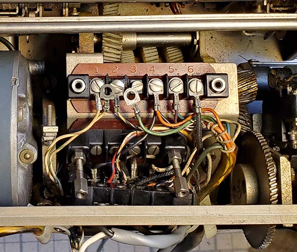
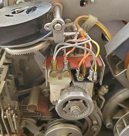
A Slight Change to M28 Compact - By removing the paper roll, there is easy access to the wiring terminal strip for the KB and the MAG lines. There are only six terminals on this strip which implies that the MAG and KB were originally (and are at present) in series. Terminals #1, #2 and #3 are used for the MAG/KB in series connections and a two conductor non-shielded cable was connected to terminals #1 and #2 for external connection to a TU. In the photo to the left, the white/violet wire and the white/green wire go to the printer magnets. The solid green wire and the white/black wire go to the keyboard. Note that immediately below the MAG/KB 1-6 terminal strip is a "double decker" terminal strip (with four terminals each.) This lower terminal strip has absolutely no connections to it. I can only suppose that this terminal strip was installed to allow some changes in the wiring if the end-user desired.

I used the original 1-6 upper terminal strip for MAG line connections on #1 and #2 and the lower 1-4 terminal strip for KB connections on #1 and #2. I used two-conductor shielded cable for both the MAG and KB lines. Length of the cables is six feet. The connections to the TU are via spade lugs to the TU terminal strip. The shields are grounded at the M28 Compact and at the TU.   I changed the M28 Compact back to original series MAG-KB connections to operate with a HAL ST-6000 in June 2021.

Homebrew TU Updates - I had the M28 Compact and the TU running with separate MAG and KB lines. After a few minutes of operation the switching transistor blew again. This must be due to back EMF from the Printer Selector Magnets. I had a 1N4004 diode across the transistor to unload the back EMF which would be the opposite polarity of the loop voltage. I checked a schematic of the HAL ST-6 to see how that TU (which KB6SCO used with this M28 Compact) unloaded the back EMF. I found that the ST-6 uses a RC filter on the transistor collector to unload the back EMF. I installed a 470 ohm in series with a .1uf 400vdc capacitor from the transistor collector to chassis-ground. The ST-6 also had a diode in series with the drive to the switching transistor base. I already had a 1N4004 diode to chassis ground on the base that was reverse biased for the normal positive base switching voltage but would limit any negative switching voltage to the base to -0.7vdc. The next test will see if the RC filter helps. Luckily, there are lots of these HV NPN transistors available and they aren't expensive,...but they shouldn't be blowing since they are rated for over 300 volts and .5A of current.

Problem Solved - M28 Compact Machine Conflicts with Manual - I don't remember ever having any trouble with my homebrew TU switching transistor when operating with the gray Model 19 but that machine has holding magnets that are connected in parallel for 60mA operation which results in a lower DCR for the magnets (around 30 ohms as I remember.) The M28 Compact measured 125 ohms DCR on the MAG line. I think the higher DCR of the magnet solenoids allowed for a much higher back EMF to develop and that's why I was now experiencing problems with the TU switching transistor. Looking at the "Compact" manual and the M28KSR schematic, each magnet solenoid should measure 125 ohms and therefore in series the DCR would be 250 ohms and in parallel the DCR would be 62 ohms. I disconnected the magnets and measured their DCR to confirm that each individual solenoid was about 125 ohms. Further wire tracing and I discovered that only one selector magnet was connected and that's why I was getting 125 ohms DCR at the MAG cable end. The manual states that on the M28 Compact the selector magnets are wired in parallel. But, each solenoid has to be connected so as not to "buck" the other. I had to experiment to find the correct connection. By adding two jumpers for a parallel connection, now the DCR of the selector magnets at the end of the cable is 62 ohms and they draw 60mA operating on the loop supply. When operating on local loop only, everything seems to work. The range finder was set to about 35 with a single selector magnet but now, with the two magnets in parallel, the range finder has to be up around 70 (60 is optimum.) Photo right shows the jumpers that I added for a parallel connection. Individual wires do exit each magnet and are routed up to the 19 pin connector located above and behind the bell. In checking the wiring of the 19 pin plug, I didn't see where any wires had ever been connected to the second magnet terminals. I had to assume then that the parallel connection was accomplished at the selector magnets. It looks like the right side magnet isn't original with the terminals being on top. I think if the right side magnet was like the left magnet, a parallel jumper connection would be much easier (and neater.) There is a fiber board cover that hides these terminals when it's installed.
 

Manual Note - I have the Teletype manual for the M28KSR Compact. As far as mechanical set ups and adjustments, that's covered extremely well. Also, the basic operation of the machine is covered with written descriptions. What's totally lacking is any schematic representations. It almost seems like Teletype went out of their way to avoid showing any wiring or any schematic representations. I've been using a standard M28KSR schematic but the similarity is only slight and all of the terminal blocks are completely different. I've heard that the Compact schematics are actually in another Teletype Corp. bulletin-manual that I don't have.

Note: June 17, 2021 - Nick England at www.navy-radio.com has just uploaded a "ton" of TTY machine data that was donated by Paul Cembura (RTTY Electronics) and within that data were a couple of schematic representations of the M28 Compact. Lots and lots of new TTY info at navy-radio.

M28 Compact Printer operating with the Homebrew TU - Now that the two selector magnets are connected in parallel and presenting 62 ohms DCR to the loop supply along with the back emf RC filter installed (to replace the reverse biased diode) in the TU, perhaps our EGC157 transistor will survive for more than a minute or two. I connected the M28 Compact up to the TU with the MAG line and the KB line separate. I then switched to TX which feeds the AFSK oscillator buffer into the input of the TU board AGC circuit. I switched off MARK HOLD and started typing. The typing continued on for several minutes with no problems. Other than the continuous error from the keyboard of typing M printing V and typing B printing X, otherwise perfect except for the heavy keyboard action. I connected up the M28 Compact/TU combo to the Samsung Tab A tablet and went to ITTY. From that signal source, the printing was perfect at 60wpm and the action of the printer was excellent. B and M printed perfectly so the error on local loop is coming from the keyboard. I'm pretty sure I have the printer, selector magnets, range finder and my old homebrew TU all functioning fine now. Next is the keyboard to see what's causing the heavy action and the two M and B errors. The two red buttons, LOC CR and LOC L F (Local Carriage Return and Local Line Feed) don't seem to work either.
 

M28 Compact Keyboard Problems - The keyboard unit is mounted to the base with four screws that are accessed from the bottom. There is one cable plug that connects to a receptacle on the left side of the machine. With the four screws out and the cable unplugged the keyboard just lifts slightly up in the front and the forward to remove from the base.

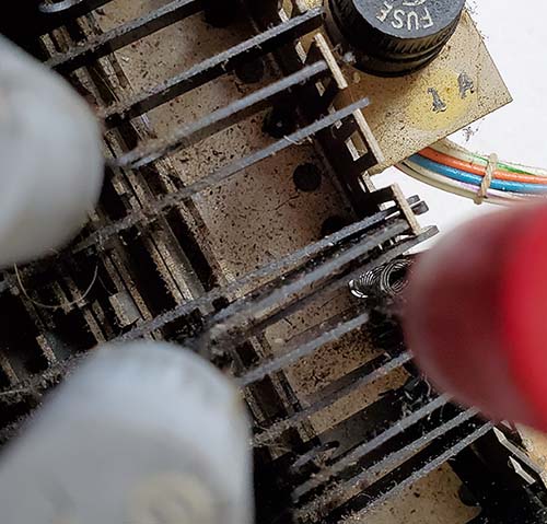
The first problem was when "B" was typed, the printer on local loop would print "X." In the photo to the right it can be seen that the "B" lever is actually inserted into the wrong rear slot and that causes it to miss some of the code bars' projections that are just above the lever in the photo. The "B" lever had to be entirely removed and straightened because it had actually been bent in order to fit into the wrong slot. The lever was straighten and then remounted correctly into the "open top" slot.

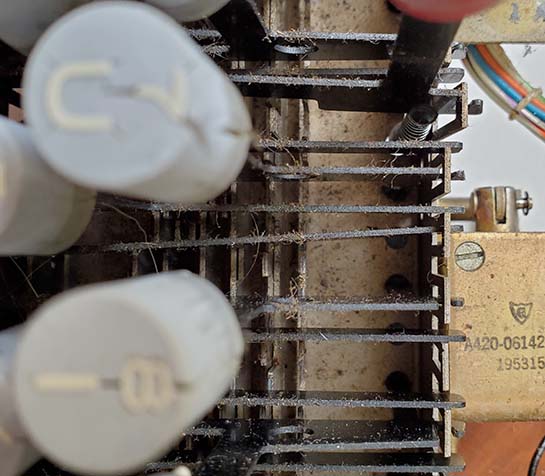
The second problem was when "M" was typed, the printer on local loop would print "V." In the photo to the right it's very obvious that the "M" lever is in the wrong rear slot. This lever wasn't bent but because it's angled so far over in order to fit into the wrong slot, it misses the projections on some of the code bars and causes the error. This lever was able to be pushed forward to slip out of the incorrect slot and then moved to the correct "open top" slot.

The LOC CR and LOC LF (the red buttons) were also out of their correct slots and wouldn't press down. These buttons actually have their own compression springs for return. They contact levers from the printer to actuate the Carriage Return and Line Feed directly.

The entire keyboard had not been serviced or cleaned in quite a long time. Obvious from the errors found, the keyboard had been carelessly worked on the last time it was serviced. It was noticed that there was a lot of oily residue on everything. The code bar action works using two sets of several nylon elbows that ride on nylon shafts, one set of levers at each end of the code bars. These nylon parts shouldn't be oiled or greased. They don't need lubrication and oil in these places will just trap dirt that will eventually restrict easy movement of these pieces. But, there was greasy gunk everywhere. Compounding the problem was a lot of what looked like pet hair mixed in with the greasy gunk. The hairs are easily visible in the two photos to the right that were taken before cleaning was performed. To fully remove the mess it was necessary to clean everything with isopropyl alcohol. When the contamination was removed, then the only oil lubrication was applied just to the felts within the mechanism. The keyboard top was then reinstalled and the complete keyboard installed back onto the M28 Compact base and the keyboard cable plugged in.

The "cleaned" keyboard mechanism's transformation was amazing. The typing action now is very light with a definite limit of movement at the end of the key lever travel. This gives the typist a positive "feel" to the TTY action. No errors were produced on the "local copy" system that I use,...keyboard output to AFSK oscillator input, then to the AFSK buffer out to the TU AGC input and the TU board output to operate the selector magnets of the printer. This separation of the keyboard and the printer actually has the TU operational and powering the selector magnets during transmit rather than the KB just breaking the local loop power supply for copy. It's now easy for the M28 Compact typist to achieve the "teletype rhythm and feel."


The Radio Gear for RTTY at WA7YBS for 2021

Interfacing the M28 Compact and Homebrew TU to the KWS-1 Transmitter and 75A-4 Receiver - The AFSK Oscillator has to be connected to the microphone input receptacle on the KWS-1. When in SSB mode, the two tones of the AFSK oscillator produce two RF frequencies that are alternately shifted by the 170hz Mark and Space switching of the DG-200 analog switch on the AFSK board. Since the carrier suppression on the KWS-1 is excellent and a mechanical filter is used for sideband suppression, only the Mark or Space tones are transmitted and these are converted to RF in the transmitter IF circuitry and then amplified in the internal linear amplifier, appearing as two alternating RF frequencies on the output. AFSK into a SSB transmitter made multiple band RTTY operation easy.

The KWS-1 - In the late-seventies, I ran my KWS-1 at 500W input on RTTY. I had moved the taps on the plate transformer to lower the plate voltage to +1000vdc and I lowered the PA screen voltage to +250vdc using the adjustment potentiometer in the circuit. This allowed me to load the transmitter to 500mA PA current and have an output of about 200 watts. I thought that since I was achieving that same EI=P, that is 2KV at 250mA or 1KV at 500mA, that I'd be within the 100% duty cycle ratings. I never thought that had caused any problems running this way over a five year period. The only damage from the 500W input operation I ever discovered was much later during a check over of the KWS-1 I found that the brown vitreous coating of the PA meter load resistor was entirely gone,...blown off,...lots of heat apparently (keydown at half an amp for the duration of transmission - ouch!)

In 2007, I had the KWS-1 operating with the M19 and a HAL ST-6 TU. By that time, I had returned the KWS-1 to +2000vdc on the PA plates, +350vdc PA screen voltage. I used the AFSK output level control and the KWS-1 microphone gain control to adjust the PA current to 250mA. This is just about 25% of full output  and resulted in about 150 watts output (a little over 600W is normal full output.) This set-up allowed the KWS-1 to operate within its specified ratings for 100% duty cycle.

The 75A-4 - The receiver I'm using isn't the same receiver that I used back in the late-seventies or even in the 2007 RTTY station. Why? Around 1995, I purchased another 75A-4 "sight unseen" off of an Internet antiques listing (it was before eBay and was the old "discussion group" type of Internet list.) It was listed in "antiques." I didn't ask any questions, I just called and said I'd take it. Well,...for $200 who cared? When the A-4 showed up it was very, very dirty and didn't function BUT it was "fully loaded," that is, it had the 4:1 vernier tuning knob and the .5kc, 3.1kc and 6kc mechanical filters. A full clean-up was necessary, new electrolytic capacitors, a few new tubes and a full alignment after which it worked quite well. Its serial number is 4470, so it's a fairly late version that already had all of the Collins upgrades installed from Collins. This is the 75A-4 receiver that's currently setup with the KWS-1.

Interconnecting Cables - A single-conductor shielded cable is used to connect the AFSK output of the TU to the KWS-1 microphone input. I still had my old cable for the remote PTT attached to the Amphenol connector on the rear of the KWS-1 so it was connected to the PTT terminals of the TU. This allows the TX-RX switch on the TU to control the KWS-1 transmit. Another shielded cable was used to connect the 500Z ohm output of the 75A-4 receiver to a 1/4" phone plug at the end of the cable. This was to allow the TU input to have a cable installed with an in-line cable-type of phone jack. This then can allow the input of the TU to be connected to the 75A-4 or to be connected to the Tab A tablet for ITTY (I made another cable with a 1/4" phone plug on one end and a 3.5mm stereo phone plug on the other for the tablet.)

I tested the KWS-1 with the homebrew TU and the Model 28 Compact with the transmitter output going into a dummy load. At 250mA of plate current the output was 150 watts. I tuned in the signal on a Racal RA-17L receiver and it sounded like FSK. For "On the Air" RTTY, I'm using my 135' CF Inv-V antenna with open feed line into a 1KW Johnson Matchbox. This multi-band antenna can be loaded on 80M, 40M and 20M.


photo above: The WA7YBS RTTY station in April 2021. The 74A-4 is on top of the KWS-1. To the right is the Model 28 "Compact" TTY machine and underneath is the resurrected 1977 WA7YBS "homebrew" RTTY TU.

"On the Air" with RTTY on April 3, 2021 - John, KB6SCO, told me about an informal RTTY get together scheduled for April 3, 2021 at 1930hrs PT on 3585kc. At 1930hrs I heard John calling CQ and he was answered by Bill, KE3BK in California. John was running an ICOM along with modern RTTY emulators. KE3BK was running a Model 28ASR machine into a Flex SDR transceiver. I was monitoring with the 75A-4, Homebrew TU and the Model 28 Compact. After a couple of exchanges, John paused to see if anyone else was ready to join. I fired up the KWS-1 and had two exchanges with John and one with Bill. Although, I copied both of them with no problems, they had minor difficulties with my RTTY signal.

RTTY with the KWS-1 - Problems,...

1. KWS-1 does drift (it always has) - external synthesizer to the ext. VFO  input is the common solution - just need to come up with a suitable synthesizer.

2. Harsh sound to AFSK tones - caused by RF getting into the TU.

Dummy Load Test - Monitored the KWS-1 output into a dummy load on an oscilloscope. In CW full power - no problems. At 25% of full power in CW - no problems. At 25% of full power in SSB with AFSK oscillator input - NO PROBLEMS! Waveform was clean as the machine sent Baudot at about 170 watts output power into the dummy load. This test implies that the problem is RF from the antenna system getting into some of the inputs of either the KWS-1 or the homebrew TU.

RF Grounds - One of the problems of running a station on the second floor of a house is how to achieve a good ground system. The first step is to tie all radio equipment including the Model 28 Compact and the Johnson Matchbox together with braided ground cable to make sure all of the equipment shielding and all bypass capacitors are acting on the same "ground" (actually when the station is on a second floor, the ground becomes more of a counterpoise.) Though I've never had a problem with RFI before in the upstairs shack maybe relocating the Johnson Matchbox closer to where the balanced feed line enters the room could also help. This would eliminate about eight feet of balanced line (which actually shouldn't radiate) along with an unnecessary knife switch that's in the feed line. This would result in the antenna feed line exiting the room almost directly behind the Johnson Matchbox (and that's probably a good idea anyway.)

Apr 7, 2021 - Moved the Johnson Matchbox to directly in front of where the feed line enters the shack. Now there's only about 8" of ladder line that runs straight to the balanced input of the Matchbox. Tested the loading capabilities using both an ART-13 and the Collins 32V-3. Both could be provided with a good match on 75M with < 2 watts of reflected power with about 120 watts input. Found the ground buss copper plate with screws. This will mount to the side of the table that the Matchbox is on and all equipment in the upstairs shack will have a ground connection to this buss bar.   

June 2021 - Still working on the upstairs ground system (off and on,...) I plan on running a continuous length of 50 feet of 1.25" wide copper braid at the base of and around three walls of the radio shack. This large braid will be connected by 0.5" wide copper braid to each station in the shack. Each station will have the equipment connected together with the same type 0.50" wide braid. The Johnson Matchbox, the ST-6000 TU, the M28 Compact will also be connected using the same type 0.50" wide braid. The first test will be to see if a connection to the AC house ground will do any good. It might, but probably not. I have plenty of the 1.25" braid so a run out the window and a drop of about 15 feet to a true grounding rod is possible, if necessary.

Jan 2022 - The 50 feet of 1.25" wide copper braid is installed and I have several stations and the antenna coupler housing now connected to this braid using 0.50" wide copper braid. Testing the KWS-1 still to come.

 
HAL ST-6000 - Testing and Integrating into the RTTY Station - June 9, 2021 - The ST-6000 did have most of the Molex shells but not the necessary pins for connecting up the unit. I had to order the pins which ended up being supplied with new shells for a minimal price. The old shell's plastic had become brittle and easily cracked, so the new shells were necessary. Since the ST-6000 standard connection is to have the TTY machine MAG line and the KB line in series running to the internal loop supply, I decided to go ahead and rewire the M28 Compact back to original with the series MAG and KB lines with a single two-conductor, shielded cable for connection to the ST-6000. This will require making a new cable which is no problem and probably better since I can retain the old cables for the homebrew TU (that I have other plans for,...like out in the shop,...to run the Model 19 machine.) The audio input cable has to be able to accept either the receiver 500Z line or the audio output from the Samsung tablet (for ITTY.) Again, I'll repurpose the old cable with a new Molex connector end to the ST-6000 and a 1/4" phone jack end (both cables from the rcvr and tablet - have 1/4" phone plug ends.) The audio output AFSK to the transmitter will use the old cable since it has the two-pin Amphenol connector that mates with the KWS-1. If I need to use the homebrew TU for transmitting, then I'll build another cable.

June 13, 2021 - Rewired the M28 Compact back to series MAG-KB line and tested operation using the ST-6000 loop supply. All worked fine, so far.

June 14, 2021 - Modified existing Audio Input cable to have a Molex pin (female socket) connector. Hooked-up the tablet and ran ITTY into the ST-6000 and the M28 Compact printed out flawlessly. Ran about ten minutes of copy - no errors. The 'scope pattern, while it is the double ellipses, seems fairly small,...maybe .375" ellipses. The small ellipses were because I had the Volume of the tablet turned almost all the way down. With the Volume at about 60% advanced the ellipses were filling about 80% of the CRT.  AFSK output is next.

Jan 26, 2022 - John, KB6SCO, gave me a call to let me know that a group of RTTY enthusiasts were getting "on the air" at 1800hrs PST on 3580kc and that should provide some "over the air" signals for RTTY testing here. I had to replace the power plug on the 75A-4 but other than that just a few reconnects and I was ready. I started hearing John at about 1745hrs calling CQ with a good strong signal - well,...he's only a mile or two away. It took a minute or two to figure out what the ellipses should look like and to get the bandwidth of the 74A-4 set up correctly. After that, I received seven perfect copy CQs from KB6SCO. I didn't hear any responses,...there weren't any to receive. At 1800hrs, John made a few more CQs which were perfect copy here but still there weren't any returns. Hmmm. John said that the main RTTY contact he was expecting had equipment trouble. Anyway, it was a good test for the ST-6000 as the TU for the M28 Compact. That combination with the 75A-4 provided perfect copy.  I couldn't join in for transmitting because I still have to connect the counterpoise/ground system to see if that will cure the RF problem with the KWS-1.

 
Here's an idea that I'm thinking about to allow using ITTY as the "test signal" but with individual Mark and Space frequency adjustability to allow operating any type of non-standard audio frequency TU at any shift. This is, of course, mainly to allow testing and operating military TUs, such as the CV-89A or the Northern Electric Type 153 Model 2. Although the upper limits of the op-amps involved is around 1mc, the upper limit of the 8038 is limited to about 300kc, so this approach won't work for IF input type TUs*.

ITTY Audio Frequency Conversion - Tone Converter - The proposed method for frequency conversion would be to build a small Tone Converter circuit board that installs inside a standard 2125hz Mark and 2295hz Space TU. As the TU functions, with ITTY as the input signal, the keying comparator op-amp in the TU would also be able to key the Tone Converter circuit board through a buffer op-amp that would then key a frequency adjustable AFSK oscillator. This AFSK oscillator would allow individual adjustment of both Mark and Space frequencies to any desired audio tone frequency and thus any desired shift (somewhat like the Dovetron TU filter adjustments.) The frequency adjustments would be with individual potentiometers for Mark and Space. The AFSK output would have gain adjustability. The output Tone Converter AFSK signal could drive any other type of audio frequency TU at any f shift. The disadvantage of this Tone Converter setup is that the "main" Mark 2125hz-Space 2295hz-170hz shift TU must be connected to ITTY first and then the internally mounted Tone Converter board "output" actually drives another TU that's being tested and it can then operate the TTY machine. The Tone Converter ICs are a ICL8038CC Function Generator chip and a DG200 micro relay. Also, a 4049 quad buffer/inverter and a few LM301 op-amps. Power is +/-12vdc available from the main TU. I'm planning on adding this Tone Converter to the WA7YBS homebrew TU (if there's room,...that box is already "stuffed.") Parts appear to be easily and cheaply available on eBay (from USA sellers.)

* There are several Function Generators on a Chip types of IC available. One that can operate at 455kc easily is the XR2206 which can actually go up to 2mc. This IC works and sets up very similar to the ICL8038CC with the same sort of external components required. If the 8038CC Audio Tone Converter works as expected, I'll try another Tone Converter for 455kc using the XR2206 or similar higher frequency IC (although, at the moment, I don't have any IF-input TUs to operate.)

 
Navy-Radio.com - Nick England's incredible website, www.navy-radio.com  has a tremendous amount of Navy RTTY gear, Navy radio stations, information, vintage photos and more. Everything about Navy equipment from very early gear, WWII, post-war and later.
 
Henry Rogers WA7YBS  © November 2007,...new info and photos added December 2009,...July 2011, additions and edit March 2014,...Internet-TTY info added July 2019,...took Real Machine RTTY down for a while July 2020,...resurrected and reintegrated Real Machine RTTY into the website in Feb 2021,...Updated, corrected and expanded ITTY information Feb 21, 2021,...added "RTTY Projects" to allow additional updates on Feb 21, 2021,...numerous minor corrections on March 24, 2021,...added the ST-6000 write-up and photo in May 2021,...ST-6000 operation with M28 Compact added June 14, 2021,...another ST-6 June 2022,...  
 

Return to Home Index


Radio Boulevard
Western Historic Radio Museum

 Vintage Radio Communication Equipment Rebuilding & Restoration Articles,

 Vintage Radio History and WHRM Radio Photo Galleries

1909 - 1969

- 60 years of Radio Technology -


This website created and maintained by: Henry Rogers - Radio Boulevard, Western Historic Radio Museum © 1997/2025