Radio
Boulevard
Wireless-Spark Era Equipment 1909 & 1912 M.H.Dodd Spark Stations Pre-WWI Wireless-Spark Era Equipment Spherical Audion Receiver ca: 1915-1917 Post-WWI Vacuum Tube Ham Gear Post-WWI Vacuum Tube Commercial Gear
1909 - 1925 |
|
|
Wireless Spark-Era Stations |
|
||
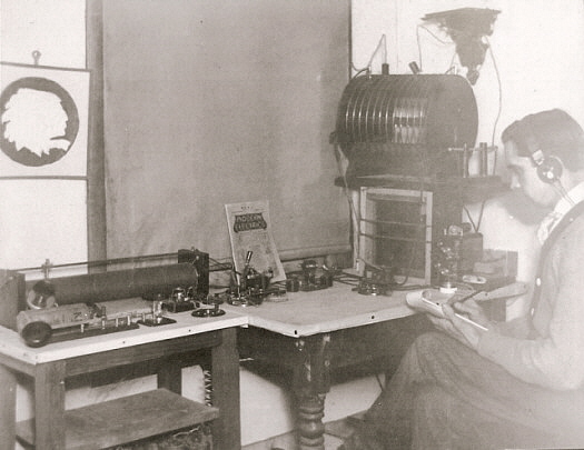
Wireless Receiver from M. H. Dodd's 1909 "Award-Winning" Spark Station Most people don't even recognize this item as a wireless receiver because it's so primitive but the vintage photograph above shows M.H.Dodd at the controls of his prize-winning 1909 wireless spark station and the receiver is very obvious setting on the smaller table to the left. Documentation on Dodd's 1909 station is provided by that fact that Dodd entered his station (a photograph and written description of his station) into a Wireless Station Contest that was held each month by Modern Electrics magazine. Dodd's station won First Prize and was featured in the June 1909 issue of Modern Electrics. The photograph used in the magazine is the same photo shown above except that the photo above is a scan of an original duplicate print of Dodd's and isn't a copy of the magazine printed photo (the original print I have has the over-exposed look at the right side - the photo in Modern Electrics doesn't.) There's a link provided to the 1909 ME Wireless Contest article (from Google Books) in the "M.H.Dodd's 1912 Wireless Station" web-article. Use the Home/Index link bottom of this page. The Tuning Inductance and Detector Stand are homebrew. Dodd wound his inductance on a form that was made from a 3" diameter 24" long piece of Bamboo - something you don't run into very often. The slider uses a spring-loaded ball contact against the windings. The single earphone headset is from the Kellogg Company and Dodd has this headset on in the 1909 photo. Also visible in the 1909 photo is a bias adjusting resistance, probably for an Electrolytic detector, a detector switch, a glass cylinder, a telephone microphone and another earphone. Bias dry cell batteries can be seen below the table. The transmitter uses two spark coils, a homemade condenser made from glass photo plates and a homemade helix. The transmitter is probably using lead acid batteries that are just visible below the larger table to the right. Most of the 1909 Station parts seen in the photo were used to construct Dodd's 1912 station (next-below.) |
|
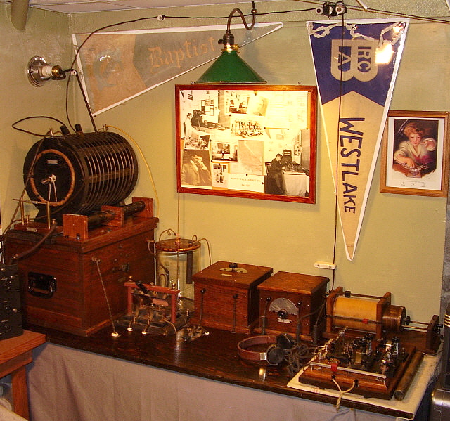
M. H. Dodd's Authentic and Complete 1912 Wireless Spark Station This is the Wireless Spark Station that M. H. Dodd built in 1912. It is a "pre-regulations" ham station that also doubled as an emergency transmitter for the San Bernardino Fire Department. The station was located in a room upstairs in the Fire Station although what purpose it would have served in an "emergency" hasn't been determined. Dodd's antenna was a three wire flat top that ran from a cupola on top of the fire station out to an observation tower located at the back of the fire station property. The Dodd station is virtually complete and was authentically reassembled in our Western Historic Radio Museum. It was displayed with photographs, taken in 1912, showing Dodd using his station. Two of the vintage photos is shown below. Dodd's station survived intact because the new regulations (the 1912 Radio Act aka the Alexander Bill that went into affect in December 14, 1912) made both Dodd and his station illegal. Rather than rebuild the equipment for 200 meter operation (it was on 600 meters) and get the new license required, Dodd disassembled the station in 1913, removed it from the Fire Station and packed it away in a large steamer trunk. Apparently, the station was his property since almost every component piece has a metal tag affixed to it with "M.H.DODD" embossed on it. The station remained in Dodd's steamer trunk for the next 86 years (with various moves Dodd made from So.Cal to Lake Tahoe and ultimately to Reno.) I discovered the "station in the trunk" in Dodd's backyard shed at his home in Reno, Nevada in November 1999. For the complete story on this amazing find, with lots of photos including several photos taken in 1912 showing Dodd at the station controls, go to Home/Index link below and then click on "M.H. Dodd's 1912 Wireless Station." |
|
photo above left: The 1912 Dodd
Wireless Station when it was on display at the Western Historic Radio
Museum in Virginia City, Nevada from 1999 up to 2012. The pennants are
original to the station and can be seen in the 1912 photos. The "CQD"
picture is an enlargement for the display of an original that Dodd had
in the station. Dodd's CQD card can be seen in the photo to the right
(next to the window frame.) The Dodd station was the most popular and
photographed display in the museum - at least with the technoid-types.
photo left: This photo was one of the last photos that Dodd took of himself at the station controls. The date is early 1913.
photo right: This is one of the earliest photos that Dodd took of himself at the station controls dating from sometime in 1912. The cork-board on the wall has pictures of Tesla and Edison along with a map of Southern California and a drawing of a wireless spark station. |
|
3ON Amateur Spark Station Parts
In 1923, John Ridgway was licensed as 3ON (later W3ON and K7AB.) He was only 11 at the time but he was able to construct quite a nice Loose Coupler using the oak boards from a discarded bed frame. The spark coil is a 1/2" Commercial Type (also shown in photo below "Spark Coils") and the sending condenser is homebrew using glass and foil. Internally, the condenser has several broken glass plates and it appears that the wires going to the terminals were disconnected. John told me that he had built a large "flat metal coil" type of helix for his station but that he ended up using parts from the helix for other projects. Spark was certainly on the way out by 1923 (spark became illegal for hams in 1927) but John was able to make a few contacts and hone his ham skills. John became SK in January 2006 at the age of 93.
|
Spark-Era Transmitter Components |
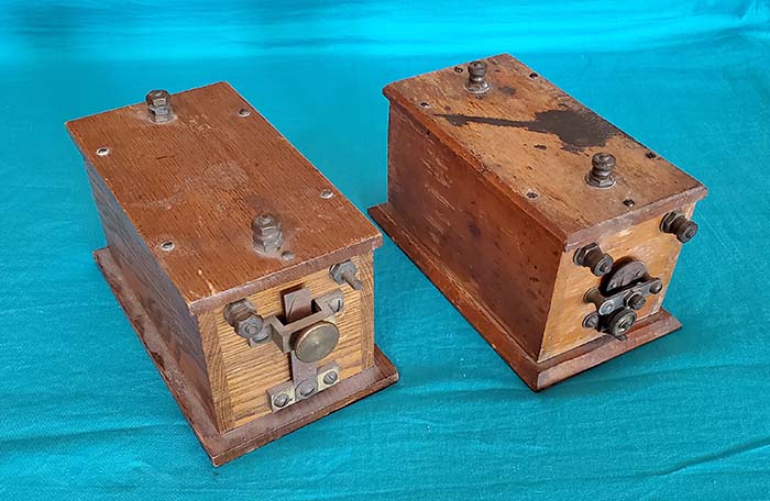
Wireless Spark Coils Spark Coils are very similar to the Ignition Coils that were used on various types of internal combustion engines. In fact, many Ignition Coils were repurposed by early hams as a method of generating the high voltages necessary for a spark transmitter. Generally, if the coil has separate connections for the primary and secondary windings and both high voltage terminals are on top of the box, it's a Spark Coil. Most Ignition coils will have a primary-secondary common ground terminal with only one "high tension" terminal. The "two terminals on top" of the Spark Coil allowed a very simple "spark gap" to be created with just a couple of solid wire pieces bent to form a gap. All Spark Coils will have a "buzzer" that acts as an interrupter on the primary because all Spark Coils were intended for DC operation from a 6 volt storage battery. The mechanical buzzer was adjusted to provide a fairly high frequency "buzz" of about 600hz to 1000hz and that changed the DC into a pulsating DC that was essentially AC for the primary of the Spark Coil. The step-up voltage was quite high with up to 10kv or more possible. At the time, Spark Coils were rated by how long of an arc they could produce. Generally, arcs were from 1/2 inch up to 1 inch or more. In the photo right, the Spark Coil on the right is marked "1 over 2" (stamped into the wood) on the bottom implying that it's a 1/2" Spark Coil. Unfortunately, neither coil has any manufacturers name anywhere (and that's common for Spark Coils.) Pre-regulations (before 1913,) many beginning electrophiles would just connect the spark gap directly to their antenna and create all kinds of interference and maybe "communicate" with another beginner doing the same thing across the street. Since there were no broadcast stations, there were very few radio listeners other than perhaps a few hams and maybe the Navy. For the most part, this primitive set up was so inefficient that interference was very local in nature (and there really wasn't much to interfere with.) Eventually, with more experience, the ham would connect up a charging condenser and a helix to get more "fire in the wire," that is, better efficiency by actually creating RF "damped waves" and then matching the spark "closed circuit" to the antenna. In many stations (usually post-regulations) Sparks Coils might be found, especially in rural areas were AC or DC house line voltage wasn't available. It was certainly possible to use a "keyed" storage battery-powered Spark Coil as the high voltage source along with a charging condenser, a stationary gap and an oscillation transformer for a fairly efficient low power spark station. |
|
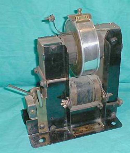
Thordarson 1/2 KW Wireless Transformer, Type R
On a 1/2KW transformer the secondary voltage is about 12KV and a 1KW transformer is double that on the secondary or about 24KV. The levers control a sliding section of the core that can be moved in or out, creating an adjustable "magnetic leakage gap" which served several purposes. Initially, it allows some control over the power output of the spark transmitter but it also serves to limit the high primary current that flowed during the discharge at the spark gap (this discharge was a momentary short on the secondary) and also to help prevent transmission at two frequencies (called double wave emission - this was usually a product of excessive coupling in the oscillation transformer.) The two wing-nut connections are for the primary and the two top connections are for the secondary. The Type R sold for $21 in 1917, just before the WWI Navy ban on amateur receiving and transmitting. This ban was not lifted until April 1919 for receiving and October 1919 for transmitting. By 1921, Spark was on the way out being replaced by vacuum tube oscillators.
|
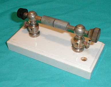
J. H. Bunnell Co. Mascot Spark Gap
An early spark gap from J. H. Bunnell, a company that generally built and sold all types of telegraph equipment. The Mascot Spark Gap advertised in Modern Electrics and Mechanics in 1914. It is mounted on a ceramic base and the tips are made of zinc. Zinc was supposed to produce a very clear "spark tone" - certainly a relative statement of the "spark days." Selling price in 1914 was $1.00 The one knob on the left is not original. These "stationary gaps" were used in spark transmitters where the source of the charging voltage was a "spark coil." Spark coils could provide a higher frequency charging rate to the sending condenser-spark gap-helix (closed circuit) by way of the "buzzer" interrupter resulting in fairly good dampening. It was also possible to use electro-chemical interrupters along with a high voltage transformer, however, most AC transformer operated stations used rotary gaps, like those shown next. |
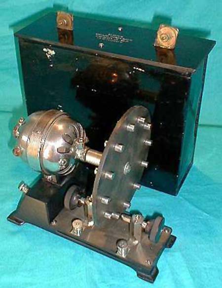
Klitzen No. 125 Rotary Spark Gap with |
Klitzen Radio Mfg. Rotary Spark Gap No.125 & Micaoil 1KW Sending Condenser There were two methods used to create efficient interruption timing so that the damped wave train would occur fast enough for the RF oscillations within each "interruption" have a high potential and not ultimately decay in amplitude too much which tended to lower the average signal level. The primary inductance and the value of the sending condenser roughly determined the radio frequency of the wave train but the interrupter determined how often the wave train pulses occurred that produced RF. One method, for example with Spark Coils, the timing was determined by the buzzer interrupter on the primary of the coil. The 1912 Dodd station used an Electrolytic Interrupter connected into the primary of the transformer to produce the timing. A second method placed the interruption in the secondary high voltage circuit. The AC transformer low frequency (60hz) input on the primary transformed the secondary voltage up but at the same low frequency. By placing a rotary interrupter in the secondary circuit, the high voltage is interrupted at a mechanically high speed, allowing the sending condenser to charge to a level that breaks down as the gap moves into place and that allows the damped wave train to start. By the time the rotating contact point has moved on, since its very slow compared to RF, many oscillations have happened. As the next rotating contact comes by the sending condenser charges, the spark gap breaks down and it all starts over again. Using a rotary gap in the secondary circuit gave the added advantage of audio frequency modulation. This was accomplished by allowing the gap discharge to occur at various random levels of the peak of the charging AC voltage (a non-synchronous rotary gap.) The varying levels of the discharge voltage and resultant different amplitude peak of the initial start of the damped waves in each wave train was heard as an audible tone allowing better copy. This Klitzen No.125 Rotary Gap is from 1920 and originally sold for $22. The approximate audio frequency can be calculated by dividing the motor RPM by 60 and multiplying by the number of discharge contacts, 12 in the case of the Klitzen 125. The rotational speed was specified at up to 4000 RPM so the frequency would be around 800Hz at maximum RPM. The Hamilton-Beach motor was a "Universal" type meaning that it was a brush and commutator motor that could operate on 110 volts AC or DC. Apparently other parts houses offered the Klitzen under their own name since there are no tags or embossing to provide a way to identify the actual manufacturer. Franklin was one such parts house that offered the No.125 as the "Franklin Rotary Spark Gap." at the astounding price of $40. It's probable the No.125 was built for Klitzen and the other suppliers by another component manufacturer. The Klitzen Micaoil Sending Condenser uses mica sheets as a dielectric and the metal box container allows insulating oil to be used to prevent arcing. The rated voltage is 30KV and that would be sufficient for about 1KW spark stations. |
Commercial-Homebrew Rotary Spark Gap
|
|
Sending Condensers
The typical homebrew Sending Condenser was assembled with each foil plate slightly over-hanging one side of the a glass plate. The next foil plate is placed on the opposite side of the glass plate and slightly over-hangs the opposite side, then another glass plate, more foil with the slight over-hang on the opposite side, etc., until the capacitor is complete. Usually, cloth tape was used to hold the assembly of glass and foil together. Once held together securely, each foil side was folded together and soldered. Wires from each plate-side would be soldered to the foil and then soldered to terminals. If looked at from either of the two sides that didn't have foil, one could see how the foil plates alternated and were separated by glass plates. The Sending Condensers shown to the right were originally mounted under the table in the 1912 Dodd Wireless Station. When the station was on display in the Western Historic Radio Museum in Virginia City, Nevada, I didn't connect the Sending Condensers under the table and had them on top of the table so they could be easily seen. Dodd used two condensers that appeared to be connected in series. This was probably to increase the voltage rating since his spark transformer secondary was 26KV. |
|
The Helix
The final device required for an efficient spark transmitter was a method that provided the inductance L needed in the primary closed circuit and then a way to couple the energy from the closed circuit into the antenna. The simplest method used a helix that was essentially a RF autotransformer. Using a pair of clip-leads, the first several turns of the helix would be connected into the primary circuit. Then another pair of clip-leads were connected to a different section of the helix coil using other turns to act as the inductance to couple to the antenna. Moving the location of the clips changed the inductances and crudely "tuned" the primary and secondary sections. The trouble with the helix was the extremely "tight" coupling allowed a multitude of harmonics to radiate from the antenna with double-wave emission being common and interference to almost everything else guaranteed. Pre-regulations procedure was for local wireless operators to "share transmitting time" due to the broad, harmonic-laden spark signals and the fact that the primitive receiving tuners with mineral detectors responded to just about any electromagnetic energy at just about any frequency. This meant that locally only one station at a time could transmit while all the others listened. Still, helixes were popular because they did allow maximum transfer of energy to the antenna and during pre-regulations just getting your signal heard was of paramount importance. At that time it didn't matter if your signal was on multiple harmonics, as long as somebody, somewhere heard you. In areas where the Navy had a presence, this was a major problem and ultimately lead to the 1912 Radio Act (effective Dec 14, 1912) that put regulations in place to try to sort out the electromagnetic chaos. The Helix shown is probably homebrew but the quality of construction is first-rate. The material is hard rubber (sometimes called Condensite) but for some reason it was painted black with a brush which gives the material an almost wooden-like appearance. Tapped holes, flat head machine screws that are properly countersunk and the beveled edge around the base all give the impression of professional construction. Then the anti-arc discharge balls at each end of the coil is an interesting touch. The coil diameter is seven inches. Date of construction is possibly before 1913 but the small size implies 200 meter operation and that would likely date the helix to sometime between 1913 and 1917. |
Wm. J. Murdock Co. Type 424 Oscillation Transformer
The Oscillation Transformer physically separated the primary "closed circuit" from the secondary "antenna circuit" and provided a method of changing the physical distance between the two coils. That allowed the electromagnetic coupling between the primary and secondary coils to be variable from "tight" to "loose" with the loose coupling giving the best selectivity or "narrowness" of the radiated signal and, if properly set-up, greatly reducing radiated harmonics. Of course, the loose coupling also reduced the amount of energy transferred to the antenna but with accurate tuning of the primary circuit and close matching of the antenna circuit a good compromise could be attained that provided a much stronger signal that was more or less just on the fundamental frequency. Compared to helix-type output couplers, the Oscillation Transformer was a vast improvement that, in combination with more efficient and selective tuners in the receivers, allowed multiple stations to be "on the air" within the same relatively "local" area (in the same "neighborhood" would still be very difficult.) The ham stations that were using AC transformers, rotary spark gaps and oscillation transformers generally put out the strongest and best sounding signals. However, being spark transmitters, interference and harmonics would be impossible to entirely eliminate (as mentioned, a lot of that type of interference was due to lack of selective tuning in the receivers of the time.) But, the Oscillation Transformer did help spark stations to reduce harmonics and provided a more efficient "tuned" transfer of energy to the antenna which generally allowed multiple stations to be "on the air" without too much local mutual interference. The Murdock Type 424 was available from about 1914 up to about 1917 with an original selling price of $4. The primary circuit was usually the smaller coil and the secondary antenna coil was the movable outer coil. Metal clips that slid onto the flat of the coil turns allowed moving the connections to change the inductances for tuning and matching. The coils are 7.5" and 5.0" in diameter. |
|
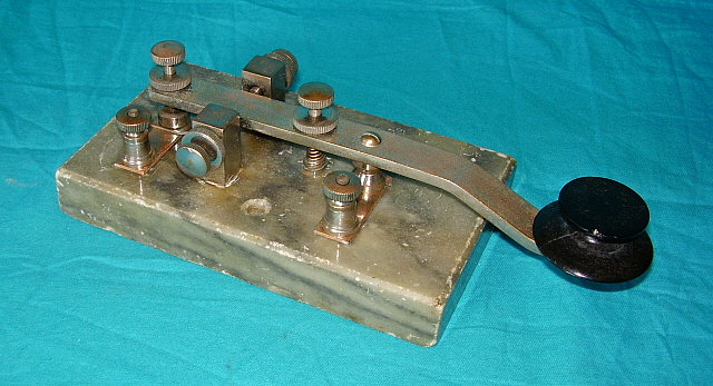
A.W. Bowman Co. for Sears & Roebuck Co.
"Meteor" Boston Key Once the amateur had assembled all of the components necessary for his Spark Transmitter, he was going to need a proper Spark Key. Since substantial current flowed when switching the primary of an AC Spark Transformer, the key's contacts had to be large in order to not overheat or become excessively pitted. Large bases were popular and marble was usually selected for insulation and weight. Boston Keys were a favorite with both hams (if they could afford them) and professionals. Most were very well made and could be adjusted to send effortlessly. A.W. Bowman started producing this style of Boston Key around 1915. Bowman's design was based on the keys produced by the Boston Navy Yard. Around 1920, Bowman contracted with Sears & Roebuck (and possibly Montgomery Wards) to produce the same key for them to sell as the "Meteor" key. The "Meteor" key is exactly like the standard Bowman except Bowman's name isn't on the Sears version (A. W. Bowman was usually stamped on the top-rear of the key lever.) Contacts are 3/8" diameter, the base is 1" thick marble and key length overall is eight inches. |
Spark-Era Receiver Components |
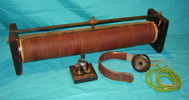
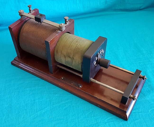
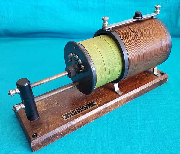
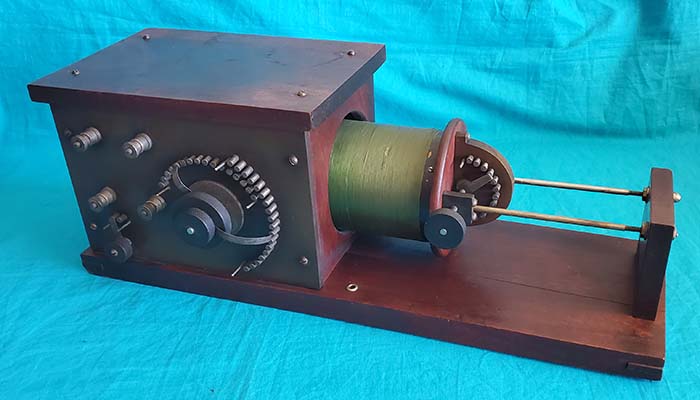
Receiving Transformers aka: Loose Couplers Before 1917, most receivers and transmitters consisted of the various components placed (or mounted) on a table with inter-connecting wires to form the circuitry needed. Since experimenting was an essential requirement for the amateur operators of the day, the ability to try various "hook-ups" was aided by these "easy to modify" station component interconnections. The receiver's Loose Coupler provided the user with the ability to crudely tune in signals and to somewhat control the selectivity of his receiver. The larger coil is the Primary Inductance and the antenna and ground are connected to this coil. The slider roughly tunes the antenna load and primary inductance to resonance for whatever frequency it is desired to receive by reducing the number of turns in the primary and, depending on the connections, may short the "dead turns" to ground. The smaller coil is the Secondary Inductance and this coil is tapped at various numbers of turns that are brought out to the contact point switch. The contact point switch roughly tunes the secondary to resonance at the frequency that is to be received by reducing the number of turns on the secondary coil and depending on how it's connected may also short out the "dead turns" to the coil return or to ground. Early "hook-ups" depended on the mutual and inherent capacitance of the loose coupler coils for the ability to tune to resonance just by varying the parameters of the inductors involved. By sliding the Secondary into the Primary, "Tight Coupling" between the Primary Inductor and the Secondary Inductor will result. Tight Coupling produces stronger signals but with a very, very broad bandwidth. By withdrawing the Secondary, "Loose Coupling" between the Primary and Secondary is achieved. Loose Coupling results in greater selectivity, at the expense of signal strength. "Loose Coupling" and the resulting "narrow" selectivity are certainly subjective terms from the time period. The typical bandwidth to be expected with "Tight Coupling" would be about 1000kc at around 400 meters - yes!, that's 1 megacycle! This isn't an exaggeration - the bandwidth is extremely broad. With "Loose Coupling" about the best selectivity or bandwidth to be expected would be about 150kc but it would be dependent on the signal levels involved. Before WWI there was NO commercial high power broadcasting so there were only a few stations on the air and these were all low power stations there weren't on the air continuously. The broad bandwidth with relatively good sensitivity gave the operators the best chance of hearing a signal. Today, using "Tight Coupling" with a Loose Coupler tuner will result in hearing ALL of the nearby AM BC band stations - simultaneously! Since you need a good antenna because you're using a mineral detector, this large antenna compounds the selectivity problem resulting in the usual Loose Coupler experience of hearing nothing but AM-BC stations regardless of the tuning or coupling involved. However, varying the proximity of the Secondary Coil to the Primary Coil to vary the coupling will also change the mutual and inherent capacitance so the desired "tuned" LC frequency resonance changes if the coupling position is moved. The proper tuning procedure was to set the desired coupling first (this just required an estimate on the operator's part on how much selectivity would be needed.) Then tune the Primary using the "slider" and Secondary using the "tapped contacts" for resonance at the desired frequency. As more and more stations began transmitting greater selectivity was needed in the receiver. This required "very loose coupling" that was achieved by withdrawing the secondary out even more. Since this also reduced received signal strength, it became of paramount importance that exact tuning of both the primary and secondary circuits be accomplished. This had the additional benefit of slightly increasing selectivity (not that it really helped that much.) More elaborate receiving set-ups would add air variable condensers to provide easily adjustable and exact "tuning to resonance" of the Primary and Secondary Inductors while allowing the coupling to remain "loose," that is, the Secondary set in an extended position. To create a Loose Coupler receiver, a mineral detector was added in series with the Secondary Inductor to the 'phones. The 'phones return was to the other end of the Secondary coil. The addition of a small telephone condenser, which was sometimes connected across the 'phones, would filter out the RF and maybe provide better audio response. Phone condensers couldn't have a large value of capacitance as this would tend to limit audio highs making copy difficult. Using just mineral detectors required a strong signal input and the only method available at the time was to use the largest antenna possible. Large antennas and excellent "earth" grounds were an absolute necessity. If a vacuum tube grid-leak detector was used instead of a mineral detector, sensitivity would increase tremendously. However, as more and more stations began transmitting, the lack of selectivity (much more apparent as the sensitivity was increased) became a serious drawback to using a Loose Coupler as the station's receiving tuner. Additionally, most hams were using damped-wave spark transmitters that produced notoriously broadband signals that would prevent reception of any other stations by other nearby hams. The era of the Loose Coupler receiver ended for hams in the early-1920s as commercial radio broadcasting started up. Also, at the same time, damped-wave spark transmitters were being replaced with vacuum tube oscillators producing continuous wave (CW) signals and vacuum tube receivers using regenerative detectors were becoming popular. It was certainly possible to use the Loose Coupler as a tuner and connect its secondary in series through a tickler coil to the grid of a vacuum tube detector and then connect a variometer in series (and wired to invert the phase relationship) between the tube plate, the earphones and the B+ battery, then place the variometer close to the tickler coil thus creating a "positive feedback" or regenerative detector receiver for CW reception - this really will work. Go to "Spherical Audion Receiver" article for details on the "how to." Use the Home-Index below to navigate. Even though that set-up was possible, as detector circuits became more and more sensitive and as commercial radio broadcasting became more and more popular, the very poor selectivity of the Loose Coupler became more and more of a problem. By the early-1920s, nearly all hams had moved to much more efficient and much more selective RF tuners. Using a Loose Coupler Receiver Today - As commercial AM Broadcasting started up in November 1920, growing both rapidly and tremendously, the loose coupler soon became virtually useless. By the mid-twenties, hundreds and hundreds of broadcasting station were "on the air" and by 1925 the "Broadcast Band" had been established from 550kc up to 1500kc. If anything put the Loose Coupler in the "obsolete bin" it would be commercial AM Broadcasting. The lack of selectivity, even at the loosest coupling, couldn't separate the broadcast stations and any weak signals are lost in the perpetual interference from very powerful broadcasting signals. At that time, hams were mostly around 200 meters or 1500kc, that is just above the broadcast band. Interference, if the AM BC station was nearby, would dominate the receiver no matter where it was tuned or how loosely coupled it was. Today, we really can't experience what it was like to use a loose coupler receiver in a low noise, no high-power interference environment that allowed the user to search for the very faint signal of some ham's rotary spark gap station in operation on 200 meters. Nowadays, ALL that can be heard will be the AM BC band. On top of that, the AM BC band now extends past the 200 meter mark, up to 1700kc. My experimenting with a loose coupler tuner and a vacuum tube detector has shown that I had to tune lower than 300kc to escape AM BC interference. At the upper end of the loose coupler tuning range, about 1500kc, there was no escaping the interference. So, today using a loose coupler receiver virtually all that can be received will be AM BC signals. At one time, Loran C "Master Station M" was located in Fallon, Nevada - just 60 miles east of my QTH. "M" operated on 100kc at 400KW. I could easily receive "M" using a loose coupler with a crystal detector with no AM-BC interference (and "M" was LOUD, even with a crystal detector.) Unfortunately, all Loran C operations were shutdown in 2008 (Loran E is now in operation, 100kc 400KW from Master Station "M" in Fallon, Nevada - 7-2024.) I haven't tried to use my Arlington-type LC to see if it's possible to receive the USN sub-comm stations on 24kc. Though these stations operate at incredible power levels and produce very strong signal levels, the MSK mode of operation does require some type of heterodyning to really detect what's going on with the signal. |
Wm. J. Murdock Co. Receiving Transformer No. 334 - Loose Coupler
William J. Murdock Company started in business in 1896 building various kinds of electrical equipment for telephone and telegraph service. Wireless equipment was added to the line as knowledge and interest about sending and receiving wireless signals became popular. The No.334 dates from 1913 or 1914 (up to 1917) and its original selling price was about $15.00. The No.334 was a high-quality apparatus with mahogany wood used for the base and matching stained poplar for the vertical pieces. The secondary end-plate is hard rubber. The size is appropriate for medium wave operation (200M) although it could certainly also be tuned to the low frequency part of the spectrum. |
|
|
|
The Radio Apparatus Company also sold by Sears-Roebuck Navy-type loose couplers will have the primary inductor enclosed or partially enclosed in a box with a front panel mounted to the box and tapped switches for adjusting the number of turns on the primary coil. Some Navy-type couplers will have an "on-off" switch (as the 5A does) that disconnects the antenna from the primary. The front panel will also have terminals for connecting the antenna and ground along with two terminals for the secondary inductor. The secondary will generally have an adjustment of the number of turns of the coil with a switch that is mounted so it can be accessed without reaching around to the front of the secondary. "TRACO" was a trade-name for The Radio Apparatus COmpany products. They were located in Pottsdam, Pennsylvania. The 5A sold for about $18 around 1917. The 5A was also sold through Sears-Roebuck. When sold by Sears there wasn't any identification tag. The front panel is hard rubber which, when exposed to bright light for years, will turn brown. The inside of this panel is black but the outside has "aged" to a greenish-brown color. The wood is poplar that is finished in the typical dark red mahogany color of the time. The upper two terminals on the front panel connect to the secondary coil. The two lower terminals are antenna (left) and ground (right) connections. The outer semi-circular contacts adjust single turns on the primary while the inner set of contacts adjusts tens of turns. |
Wm. Duck Co. The larger Loose Couplers were sometimes called "Arlington" types since they could tune to the very long wavelengths for time signal reception. The "Time Signal" was sent by USN station NAA located in Arlington, VA operating at VLF frequencies. NAA was built in 1912 - see the write-up below. Arlington-type Loose Couplers will have a greater number of turns on the primary and secondary with larger coil dimensions. The Loose Coupler (LC) shown is not marked but appears identical the Signal R-22 from about 1914-1917. However, Signal Electric usually stamped "SIGNAL" into the top of the smaller front wood block that supports the secondary coil support rods and this loose coupler doesn't have that stamping. It's probable that this LC is from Wm. Duck Co., as the "Duck-types" are also identical to the one shown in the photo (when I purchased this LC 40+ years ago, I was told it was a Wm. Duck.) As to the Duck being able to tune to VLF, this LC with a mineral detector, phones and a 125' antenna could easily receive the Loran Station "M" in Fallon, Nevada operating on 100kc - not exactly VLF, but close. LC Receivers using mineral detectors will only respond to amplitude modulated signals. During the "wireless era" nearly all signals were from "spark" transmitters that were actually called "damped wave" transmitters that used various types of interrupters. e.g., buzzers, electrolytic interrupters or rotary interrupters. The signals from these transmitters were essentially a keyed modulated carrier wave that could be demodulated by the crystal/mineral detector and become audible in the 'phones. Likewise, "radiophone" signals were voice amplitude modulated carrier wave signals that could also be demodulated by the mineral detector and become audible in the 'phones. By the early 1920s, vacuum tube continuous wave (CW) transmitters were becoming popular. Also, the Navy was using arc transmitters and Alexanderson Alternators that were also CW transmitters. These of types of signals can't be demodulated properly using just a mineral detector (other than maybe hearing the carrier turn on and off with very strong signals.) |
Wm. Duck Company |
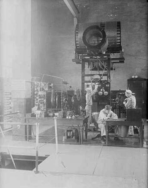
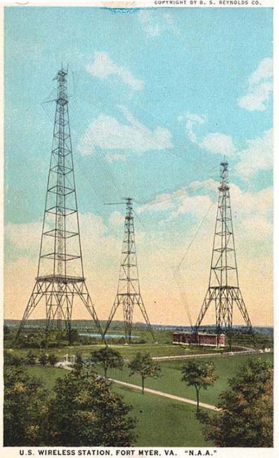
"The Three Sisters" Radio Towers and
The Navy wireless station at Arlington, Virginia was built in 1912, at
the southwestern end of Ft. Myer, on land that was given to the Navy by
the War Department. After the construction, the
area became known as "Radio, Virginia" but the NAA location was
also often referred to as "Ft. Myer" or "Arlington." The main tower was 600 ft tall and two flanking towers were 450 ft tall. The
antenna was a wire array suspended from the towers. The initial transmitter was a 100KW
rotary spark type but it was soon joined by a more efficient 35KW arc
transmitter. In Sept.
1915, NAA radio-communicated with the Mare Island Naval Shipyard in
California becoming the first direct transcontinental two-way radio communication.
Shortly after that, NAA exchanged a short message with Pearl Harbor becoming
(at that time) the longest distance direct two-way radio communication
at just under 5000 miles. In 1923, two additional towers were added
(250' tall.) In the 1930s, the towers were painted orange due to an
increase in airplane traffic and several "close-calls." Air traffic only
increased and "The Three Sisters" were razed in 1941 due their hazardous
location near the new and very busy Washington National Airport. Prior
to the shutdown, all of the equipment and duties were moved to NSS (built in
1918,) the Navy station at Annapolis. In 1961, the call NAA was
reassigned to the Navy VLF Submarine Communications station at Cutler, Maine. photo left: Inside NAA showing the transmitter, probably the
100KW transmitter. Additional equipment can be seen on the table to the
left. Note the table fan that appears to be for cooling some of the
apparatus. Sometimes fans were used to keep stationary spark gaps cool.
On the floor below the table appears to be a large transformer (not
large enough for the 100KW station.) photo right: NAA Arlington - The station house and the "Three Sisters" antenna towers. The antenna consisted of multiple-wire "flat-tops" creating a "tilted" triangular array with multiple feed points. The 600 ft tower is on the left. The distance between the two 450ft towers is 350 feet and the distance mid-point between the 450ft towers to the 600ft tower is also 350 feet. The approximate antenna dimensions would have been the 350ft side between the two 450ft towers plus each 392ft side to the 600ft tower making the total antenna length 1134ft. The cost to build NAA in 1912 was $250,000. This post card dates from about 1915. |
|
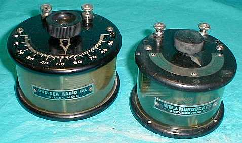
Chelsea Radio Co. Wm. J. Murdock Co. These air variable condensers were generally used with Loose Couplers to provide more accurate tuning of the primary and secondary inductances in amateur wireless receivers. These two happen to have plastic covers so the plates are visible but some earlier versions had the entire housing cast out of hard rubber or bakelite. The Murdock is from about 1915 and the Chelsea is from about 1920. Up to about 1912, a loose coupler receiver would only use a variable condenser in the primary (antenna) circuit. It was thought at the time that only accurate tuning of the antenna circuit was necessary and that alone resulted in the best transfer of energy to the secondary circuit. The secondary circuit only needed to be roughly tuned using a tapped switch to select the number of secondary turns and that resulted in the best signal reception. As it became necessary to use "looser coupling" for better selectivity (due to multiple stations "on the air") that resulted in much weaker signals in the receiver. It became apparent to the hams that accurate tuning of the secondary was going to be necessary for greater selectivity and better reception of weaker signals with looser coupling. After about 1912, due to the higher frequency of operation (1500kc and up,) later receiver set-ups usually added another variable condenser to accurately tune the secondary circuit to resonate with the primary/antenna circuit for the best transfer of energy and the best reception of selected multiple weak signals. As more sensitive mineral detectors became available, distance of reception increased and successful reception became a ham from another state and not just "the other" local ham. |
Complete Wireless Era Mineral Detector Receivers |
Peerless Wireless Company "High Grade Radio Apparatus" Model B Peerless Wireless Company was located in Detroit, Michigan and offered this assembled "Model B" receiver using a Loose Coupler tuner with crystal detector as their "High Grade Radio Apparatus." The original detector was replaced with a later, after-market Galena detector that was probably of better quality (and more sensitive) than the original. Two sets of earphones can be used with this set - the two sets of "TEL" terminals are connected in parallel. The large contact switch tunes the primary coil by selecting the number of turns. The secondary turns are selected by the contact switch on the front of the secondary coil form. The small switch allows the antenna to be removed from the primary coil - an early form of "send -receive" switch. A fixed condenser is located under the board. One would think that the Model B dates from around 1914 to 1917 but many of the radio house catalogs from 1920 to 1922 show similar types of primitive receivers intended as an entry-level device capable of picking up a local broadcast station. No batteries required,...just connect to antenna, ground and 'phones.
|
Pre-WWI Vacuum Tube Wireless Receivers |
Spherical Audion Receiver - ca: 1915 to 1917 |
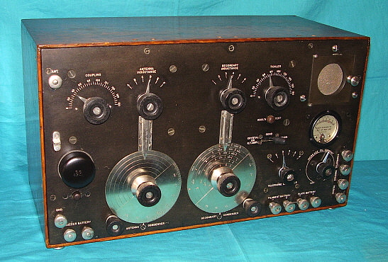
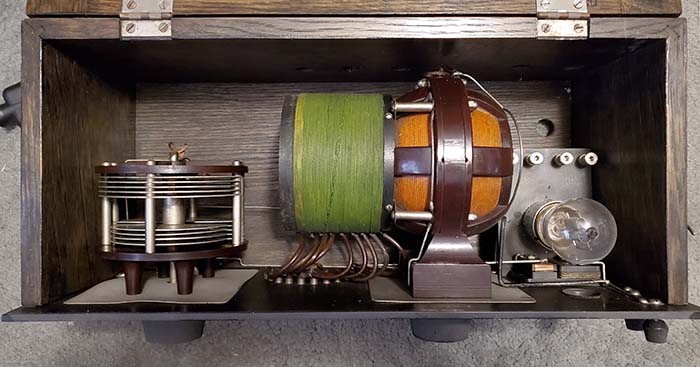
The builder of this wonderful Spherical Audion Receiver is unknown. The quality of workmanship, including the stamped number nomenclature and etched scales on the front panel along with some of the clever mechanical features, seem to imply a professional-level of design and construction. But, does that indicate a special-build product of an unknown commercial outfit? Of course, there were some incredibly talented amateurs that were fully capable of building this receiver. Dating is just speculation,...as is most of the following paragraph. Dating the Audion Receiver to between 1915 and 1917 was arrived at by noting that the circuit is non-regenerative. Although DeForest and Armstrong both claimed the regenerative detector invention in 1912, Armstrong was initially awarded the patent in 1914. The first commercially-built regenerative receiver was the Paragon RA-6 from 1916 though, as a counter-argument, the WWI SCR-59 uses a non-regenerative detector (and most of those were built in 1918.) Another indicator would be the "dead-turns" (unused sections of tapped inductors) are not grounded and that can cause losses due to stray coupling. "Dead-turns" were normally grounded after about 1917. Then there's the Spherical Audion tube itself. Although DeForest first patented the triode in 1906, it took him some time to be able to commercially manufacture them. The earliest Audions had tubular envelopes. The Spherical Audion tube was a bit later as the glass manufacturer (McCandless) suggested the spherical blub shape would be easier to produce. The Spherical Audion started to be produced in 1908. DeForest came out with the RJ-4 Audion Control Box in 1910 but was still making changes in the Audion up to 1912 and later. DeForest had a contract with the Signal Corps to produce 10,000 Spherical Audions for WWI indicating this type of tube was still being produced in 1917. DeForest couldn't meet the specifications consistently and the contract was eventually given to GE. This receiver is most likely an amateur-built receiver dating from 1915 to 1917. If it was professionally-built, one would think the company or individual builder would have put a name on the receiver. Based on the design and its clever mechanical devices, its use of a Spherical Audion tube and the fact that it's a "panel set" type of receiver, it's my belief that this receiver was built between 1915 and early-1917 - probably by a very talented amateur. |
|
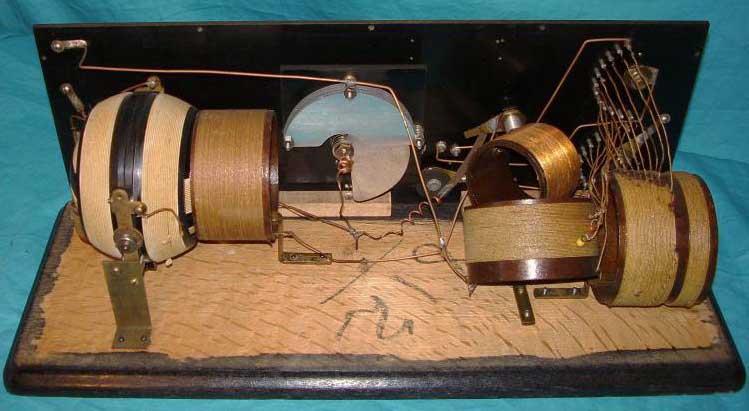
Circuit and Construction Description - The circuit uses a Loose Coupler tuner and a non-regenerative, grid-leak detector. On the lower right side of the panel is an interesting dual control the outer knob of which varies the secondary inductance coupling via a bell crank while the inner knob selects the secondary turns. Another clever control is the large antenna tuning series condenser on the upper left side of the panel. If the knob is rotated to either end of its scale and the metal pointer put into contact with either of the stop pins, the condenser is then shorted (rotor to stator) and essentially taken out of the circuit. The back-up crystal detector appears to have been a somewhat later addition since the quality of workmanship doesn't match that of the original construction. A crystal detector was a common addition to early vacuum tube receivers as it allowed the receiver to still be used if batteries were depleted or if the tube or tubes failed. The cabinet is solid mahogany that has been stained a medium red color. The internally mounted base that the loose coupler and bell crank are mounted on is made out of Redwood. The use of Redwood implies that the receiver was probably built somewhere on the west coast (probably California.) The front panel is .75" thick hard rubber that has nomenclature that is a combination of stamped numbers and scribed scales. The nomenclature is filled with white paint. |
Receiver Controls and Components - The left side (as viewed from the front) of the receiver is the Antenna Tuning circuit. The large knob controls the massive antenna tuning condenser. Each stop pin is connected to the stator and the knob pointer is connected to the rotor so placing the pointer in contact with either stop pin shorts-out the condenser and effectively removes it from the circuit. The condenser is in series with the primary inductance of the loose coupler to ground. The two contact point switches select the number of turns on the primary of the loose coupler thereby crudely tuning the antenna circuit or primary circuit of the receiver. As seen in the photo to the right, the Antenna condenser is at the upper right and the loose coupler takes up most of the bottom base board of the receiver. The right side of the receiver (viewed from the front) controls the secondary tuning using a small air variable condenser that's connected in parallel with the secondary inductance of the loose coupler. The larger (rear) coaxial control knob allows selecting the number of turns on the secondary of the loose coupler. The smaller (forward) knob is attached to a control shaft that connects to a internally mounted bell-crank type of arm the moves the secondary coil into or out of the primary coil thereby controlling the coupling. The photo-right shows the bell crank and how it can move the loose coupler secondary into and out of the primary coil. The control next to the audion tube is a large E.I.Co. porcelain rheostat for adjusting the audion filament (the porcelain rheostat is obvious in the photo-right.) The switch below the audion connects and disconnects the A battery to the audion filament. The switch below the crystal detector selects Crystal detector or Audion detector. The antenna and ground connections are large solid brass terminals mounted on the right side of the cabinet and can be seen in the photo-right on the left side rear. The insulated wiring for the antenna and ground terminals is routed under the base board (held in place with "hammer-in" staples) and the wires come up through holes to connect to the Antenna side of the receiver. The left side panel terminals are for the A battery with the large binding post cap being positive. The middle panel terminals are for the 'phones. The right side panel terminals are for plate voltage battery connections. |
|
|
Restoration - 1988
- I've owned this Spherical Audion Receiver since 1988. I saw it at a
TRW-SCARS swap meet but didn't buy it. Two weeks later, I saw it at a
California Historical Radio Society swap meet (same seller and $50
cheaper) where I made the purchase. Most the metal parts were nickel-plated brass but most pieces had areas where the plating was gone and others where the plating didn't match. At the time, I was really "into nickel-plating" so I dismounted all of the metal parts (including the switch contact points) and re-nickel-plated all of the parts (yes, I did the nickel plating at home - it's pretty easy if you have the nickel sulfate solution and nickel anodes.) My thought then was that all of the metal parts would then match in color and the new plating would fix scratches and wear, which it did. The massive Antenna Tuning Condenser is so heavy that it was actually bending the front panel. I rebuilt the condenser and fixed the mounting that had loosened and probably had been causing the bending. The stop pins on the Antenna Tuning Condenser needed to be re-wired back to their original purpose. The pointer on the knob was crudely bent and needed to be re-bent to match the shape of the other pointers. Most of the electrical wiring needed to be redone. Several wires had come loose or had been disconnected in the past. Several other wires were missing. I replaced a lot of the black sleeving that had dried and broken. I used vintage sleeving (black lacquered cloth tubing.) I tried to maintain the original wiring circuit and didn't modify anything in an attempt to "modernize" the design of this obviously primitive receiver. I didn't do anything to the mahogany cabinet. It has always been in very good condition. Originally, there was a back panel that was hinge-mounted. The two hinges were still present but the back cover was "long gone" when I got the receiver. I never have built a replica back for the receiver since I really don't know what it looked like or even what material was used. If I was going to make a replica, I'd use 0.25" thick hard rubber (Condensite) if I could find it.For displaying the SARX I built a spherical audion replica tube using an already broken Western Electric "tennis ball" tube. I glued the correct type of lamp base to the top tip of the envelope and then using epoxy I built up a bottom for the replica tube with the two wires exiting from that end. From a distance it's almost convincing. NOTE: For excruciating OCD details on this Spherical Audion Receiver, about its discovery, its 1988 restoration, the 1989 ARC article, the 2022 Refurbishment and testing, plus how to add a "no mods" regeneration using all external components along with adding a "no mods" external audio amplification,...go to "Spherical Audion Receiver" - use Home-Index bottom of this page. |
Post-WWI Vacuum Tube Receivers The USA entered WWI in April 1917. The Navy quickly put a ban on all ham receiving or transmitting. Virtually no sales of amateur wireless apparatus happened from April 1917 until the ban was lifted. The receiving ban was lifted in April 1919 and the transmitting ban was lifted in October 1919. During the duration of the ban, both transmitting and receiving circuits had evolved rapidly. Also, there were many improvements in vacuum tube technology. Undoubtedly, the rapid technological evolution was due to the new wireless communications requirements of WWI. Spark transmitters were still around, just barely, after the transmitting ban was lifted but the "death knell" to Spark (at least as far as hams were concerned) came after the December 1921 Amateur Transatlantic Tests when Paul Godley commented (after returning from Scotland) that "the 50 watt vacuum tube oscillators were stronger and easier to copy than the 1KW spark transmitters." After that, the hams pretty much abandoned Spark and went over enthusiastically to vacuum tube transmitters. In examining many, many hundreds of 1921 to 1924 QSL cards, many 1921 QSLs do show "spark" being used for the contact. In 1922, occasionally "spark equipment" was seen listed as the transmitter. By 1923-4, the listing of "spark equipment" (that wasn't used for the QSO) was sometimes shown but usually accompanied by also listing "vacuum tube oscillator equipment" (that was used.) After 1924, "spark equipment" was never shown on the literally hundreds of early twenties QSL cards I've examined. The latest spark-QSL I've seen was from Dec 10, 1924. Spark became illegal for hams to use in 1927. The dramatic evolution in technology between the "Spark Era" and the post-WWI "Vacuum Tube Era" can easily be seen in the following equipment. |
|
Navy Type SE-1420 - Wireless Specialty Apparatus Co. This is the "Navy Destroyer" receiver designed by Louis Hazeltine at the end of WWI (1918.) Hazeltine was a Stevens Institute graduate and then subsequently became an instructor there. The design request came from a former Hazeltine student who was now in charge of receiver development at the Washington Navy Shipyard. The Navy wanted a receiver that was capable of operation in the presence of nearby spark and arc transmitters. Hazeltine achieved this selectivity by using a sophisticated Antenna Tuner that was completely shielded and only coupled to the Secondary Tuner by a small variable coupling coil. The sensitivity of the SE-1420 was greatly enhanced by the variometer-controlled regeneration circuit. Although the receiver can be operated "stand-alone," generally there was a two-stage audio amplifier available for even better signal reproduction. The first Navy contracts were built by either AMRAD or Wireless Specialty Apparatus. The circuit uses a single vacuum tube (either a VT-1 or Moorhead ER) as a three-circuit tuner with a regenerative/autodyne detector. Wavelengths covered were from 300 meters to about 7500 meters. The entire cabinet is lined inside with grounded copper sheet metal with an additional copper shield to provide complete isolation between the Antenna Tuner section and the Secondary Tuner circuit resulting in great selectivity and immunity to interference. This complete shielding also eliminated stray pickup and totally eliminated hand-capacity effects when operated as an autodyne detector. SE-1420 type receivers were built by various contractors though most of the 1920s. The Coast Guard version, CGR-5A (SE-1420C) was contacted in June, 1927. The U.S. Army Signal Corps designated the later SE-1420 versions as the BC-131. There were several variations and upgrades to the receivers, some with different frequency coverage but the same basic style is easily recognized. The various end users were the Navy, the Army and the Coast Guard. Wireless Specialty Apparatus was organized in 1907 by Greenleaf Pickard and John Firth. United Fruit Company purchased WSA in 1911. In 1920, United Fruit became part of the cross-licensing arrangement headed by GE (and included RCA, AT&T and Westinghouse) because UF/WSA owned all crystal detector patents (because of Pickard.) Around the same time, WSA started to provide a commercial version of the SE-1420 designated as the IP-501. The Triode Type B, Two-Stage Audio Amplifier was also offered with the IP-501 along with a Long Wave Adaptor to allow tuning into the VLF range. Probably because of the cross-licensing, these WSA receivers and associated equipment were sold by RCA until 1923, when WSA was purchased by RCA. From 1923 to 1927, RCA continued to sell marine radios built exclusively for them by WSA. In 1927, RCA combined WSA with another purchased company, Independent Wireless Company, and created Radiomarine Corporation of America which operated as a subsidiary-service of RCA. RMCA continued to build and sell the IP-501 and IP-501A into the early 1930s. The SE-1420 shown above is an early type from a 1919 or 1920 contract built by WSA. I've owned this SE-1420 since 1990 but the restoration had remained unfinished due lack of detailed photos of what the missing complex tube socket looked like. In 2009, armed with new detailed information, I replicated the socket and completed the SE-1420 restoration. Although the restoration used several replica and non-original parts, authentic vintage material and techniques were utilized in the rebuilding of the receiver. The SE-1420 is a great performer and has received airport NDBs from all over North America. More details on the restoration and performance in our web article. For the ultimate information source on the SE-1420, IP-501 and IP-501A wireless receivers that includes history, construction, restoration and operation of these marvelous receivers and also includes "Tuning in NDBs with the IP-501-A" see "WSA & RMCA - SE-1420, IP-501 & IP-501-A - The Classic Shipboard Wireless Receivers" in the navigation index below. |
|
||||||||
Adams-Morgan Co. - Manufacturer "Paragon" RA-10/DA-2 Regenerative Receiver/Detector & Audio Amplifier The Paragon Receiver was
designed by the quintessential ham and radio engineer, Paul Godley. A
favorite of radio amateurs, both spark and CW ops, the Paragon RA-10 tuner was first offered in 1920. Later, in
1922, the DA-2 detector and two-stage audio amplifier became available. Paul
Godley had designed the RA-6 - the first commercially built shortwave
regenerative receiver - prior to WWI. After the war ban was lifted in
late-1919, Adams-Morgan and Chicago Radio Labs still offered the RA-6 for
awhile. Godley redesigned the RA-6 into an updated and "modern - for the
times" three-circuit tuner that featured a tunable primary using tap
switches, a variable coupling coil for the secondary plus an air variable condenser
for frequency tuning. Regeneration used a variometer in the plate circuit
wired to invert the phase and EM couple to the secondary providing positive
feedback. By tuning the variometer L to resonate with the grid circuit, as the
variometer approached resonance, the inter-electrode capacitance of the
detector tube allowed some feedback. However, it was the variometer's EM field that increased the in-phase coupling to
the secondary coil (mounted on the side of the variometer,) providing the positive feedback
and amplification at the detector. Too much feedback and the detector would break into
oscillation and this turned the regenerative detector into an autodyne
detector that could be used for CW signal reception. This updated receiver was designated
the RA-10 and it became available in 1920. But, it was just a tuner. The
purchaser had to add the necessary external components to complete the
receiver and that was usually a VT detector control box to start with. An
audio amplifier could also be added to make the RA-10 a first-class receiver
of its day. Hams had always been using this component approach and the RA-10 provided
all of the difficult to build essentials for a regeneration detector
receiver. Adams-Morgan Company did offer a VT control box for use with the
RA-10 but most hams just built their own.
|
A. H. Grebe & Co., Inc.
|
Since a pure-tungsten filament, argon gas detector tube (UV-200) was used in the Grebe CR receivers, when setting up the
receivers, a method of adjusting the detector plate voltage would have
been necessary. In the early twenties, a plate potentiometer was used that
allowed varying the detector voltage by about six volts (the potential
of the A battery.) By using the +18vdc tap on the detector
battery one could adjust the plate voltage from +18vdc to +24vdc. There's an interaction between the filament voltage and the detector plate
voltage so having the plate voltage
adjustable generally means one could find the optimum combination for best sensitivity by
setting the filament and plate voltages without the receiver
detector oscillating. Once the filament and plate voltages were set,
then the regeneration could be increased for best sensitivity or for an
oscillating condition for CW reception. For Broadcast
reception, regeneration would be set to just before the detector breaks into
oscillation. As the receiver is tuned to different frequencies, usually
only the regeneration control will require adjustment. For regeneration to take place using a "variometer in the plate circuit" the variometer has to be connected properly to reverse the phase of the plate signal and then allow the EM field of the variometer to couple to the "grid tuning" coil. This allows positive feedback to take place and add to the incoming grid signal as the variometer L tunes the plate to grid. As the plate approaches resonance, the EM field increases allowing more coupling and positive feedback which increases amplification that results in an improved sensitivity. Grebe achieved the EM coupling in the simplest method possible - mounting the "grid tuning" coil on the variometer. As can be seen in the photograph to the left, the CR-5 only has the grid tuning coil, there isn't a primary coil or a coupling coil at all. The tap switches allow selecting of the number of coil turns to change the tuning range. |
Since exactly the same CR-5 tuner is used in the CR-9, providing
tuning from 100kc up to 2000kc, the CR-9 was a decent, useable Broadcast
receiver in 1921-22 because of its built-in two-stage Audio Amplifier
circuit. Regulations at that time had all BC stations on 360 meters or 400
meters, so the CR-9 could successfully receive these early Broadcast stations.
Grebe did market the CR-9 as a Broadcast receiver for a while and sold thousands of
them (it's one of the most common "CR" receivers.) To achieve maximum selectivity with a two-circuit tuner, the regeneration must be just before or just after the oscillation point. For AM voice transmissions, just before oscillation will provide best sensitivity and best selectivity. For CW, just after the oscillation point also provides best performance. One will note that if the regeneration is not at the oscillation point (either just before or just after oscillation) several signals will be received simultaneously since there won't be much selectivity and the sensitivity will be down quite a bit. One also had to be aware that, if the detector was oscillating and there wasn't any isolation between the detector and the antenna (isolation could be provided using the RORN RF amplifier,) a carrier wave would be generated by the receiver's oscillating detector at its tuned frequency that would then be radiated by the antenna. Simple regenerative detectors that were misadjusted by neophyte radio enthusiasts caused many of the cases of neighborhood radio interference in the early-twenties. Since two-circuit tuners were not all that selective, even at the oscillation point, most serious radio operators preferred the three-circuit tuner with a primary tuner, a coupler with secondary tuner and a regeneration control. Grebe did offer the CR-3 and CR-8 receivers that used three-circuit tuners. However, the two-circuit tuner of the CR-5 or CR-9 could be operated with a separate RF amplifier, such as the Grebe RORN, to improve both selectivity and sensitivity. Also, the RORK Two-Stage Audio Amplifier could be used with the CR-5 for loudspeaker reproduction. |
The binding post caps aren't original Grebe types and the cabinet metal tag is missing on this CR-9 example |
Standard Assembling Company Three-Circuit Regenerative Receiver-Tuner The Standard Assembling Company offered this regenerative tuner utilizing a Deforest tuner and Duo-lateral Coils for $50 in 1921. It was also available in kit form for $45. The primary circuit inductance is on the left, the center inductor is the secondary circuit and the right side inductor is the tickler. Moving the primary coil's proximity to the secondary coil changes the Coupling. Moving the Tickler coil's proximity to the secondary coil increases/decreases regenerative feedback. By selecting various coil sizes the tuning range can be changed. Several companies made these types of plug-in coils for the DeForest tuner. Using a DeForest type tuner can be very annoying because the location of the adjusting knobs requires the operator to reach over the coils. If the tickler is set to regenerate for CW reception, rampant EM fields are generated around the controls and the inductances. The hand capacity involved in making adjustments de-tunes the receiver resulting in temporary settings that change soon as the hand is removed. To alleviate that problem the Standard tuner has an air variable condenser TICKLER for adjusting the feedback away from the coils. This is an interesting addition in that the Tickler coil can be set to approximately where feedback via EM coupling is going to happen and then the Tickler variable condenser can "fine adjust" the feedback for maximum sensitivity. When doing the wiring of the set, the builder had to assure that the Tickler coil was "phased" correctly to allow positive feedback through EM coupling to the secondary coil to occur. However, with all of the exposed coils and the unshielded panel, when the tuner is regenerating one has to expect significant hand-capacity effects. Or,...one could just listen to radiophone broadcasts. |
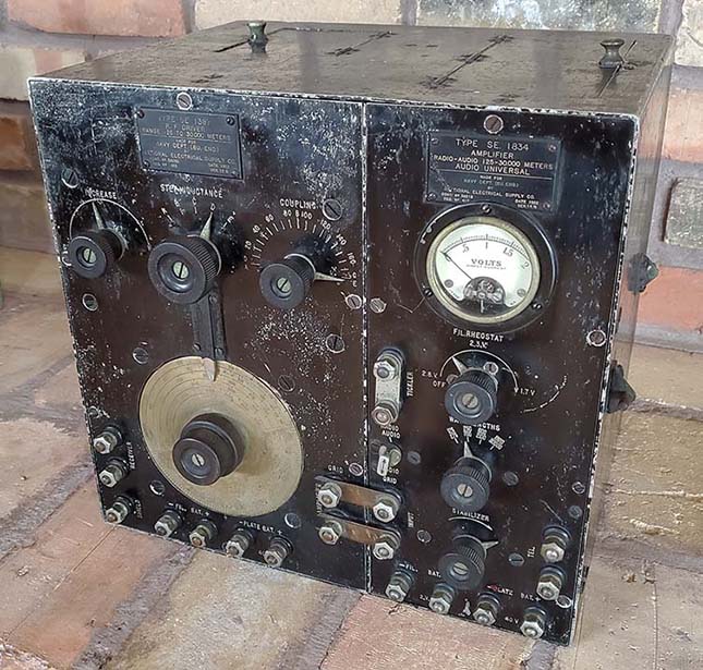
Navy Department - Bureau of Engineering - NESCO - National Electrical Supply Company SE-1387 R.F. Driver & SE-1834 Universal Amplifier The SE-143 was a WWI Receiver that was essentially a RF Tuner. It was used extensively by the Navy and other versions, like the IP-500, were used by commercial users. The SE-143 didn't have an onboard detector or audio amplifier. These components were externally added to the SE-143 installation for a complete receiver. During WWI, the detector was usually a mineral-type that might provide multiple types of detector minerals. The SE-143 could also operate with an external regenerative detector tube and the receiver provides a "Tickler" coil (variable inductance) connection for that function. The audio amplifier of the time was usually a single stage circuit using an Moorhead ER or a WECO VT-1 triode tube. As radio evolved post-WWI, RF amplifiers used ahead of a regenerative detector provided stronger signals and increased isolation of the oscillating detector from the antenna. By 1922, several types of devices were available to improve the older receivers, specifically the SE-143. The SE-1387 is a R.F. Driver that tunes from 125M to 30,000M. It uses a single WECO 215A tube RF amplifier that's designed to take the "tuned" LC that the SE-143 provided and use that as the "tuned" input signal (marked RECEIVER) to the TRF stage of the SE-1387. Since the SE-143 didn't have an onboard detector, the output of the SE-1387 is coupled to the input of the SE-1834, an "Amplifier - Audio Universal." The SE-1834 uses six WECO 215-A tubes. The input is from a variable "coupler" coil in the SE-1387 to a detector tube in the SE-1834. The detector input is roughly tuned by selecting the proper frequency within the 125M to 30,000M range. The SE-143 Tickler connection is connected to the Tickler terminals of the SE-1834 with the link removed. This would have SE-143 operating with one stage of TRF amplification, a regenerative detector and five stages of audio amplification. For receivers that didn't provide a Tickler coil, the link was left connected and the detector operated as a "non-regenerative" detector. The switch selecting "Radio Audio" and "Audio Grid" determines if the first stage acts as a detector (RF) or if it acts as an audio amplifier (audio grid.) Generally, the SE-1387 and SE-1834 combination was specifically for use with the SE-143 but other many other types of receivers and combinations could accommodated using the switches and links provided. NESCO was the National Electrical Supply Company. They were located in Washington D.C. and began operating in the late-1890s. They were very involved with early Navy equipment. Reginald Fessenden also had a company called NESCO that was the National Electrical Signaling Company but it was out of business before WWI started. NESCO changed their name in the late-thirties to National Electrical Machine Shops then using the acronym NEMS. In the 1950s, NEMS worked with Alan Clark building NEMS-CLARK VHF receivers. |
|
Sydney J. Fass Sydney J. Fass had been a commercial sea-going and maritime shore radio operator since 1909. He was active in San Francisco's early radio amateur community. Fass started a radio business, probably selling and servicing radios, that was located within San Francisco's famous "The White House" - a large department store located on Grant and Sutter in San Francisco. Fass' radio business had an impressive history as "the longest, continuously operating radio business in San Francisco." The White House closed in 1965. The homebrew radio shown is a three-circuit tuner using three tubes that was built by Syndey Fass in the early twenties. The variometers and the vario-coupler appear to be from around 1921 and were probably built by Remler. The audio interstage transformers are also very early twenties vintage from an unknown builder and labeled as "Amplifying Transformer." A Lemco grid leak condenser is used (Lemco was Lee Electric & Manufacturing Company in San Francisco, famous for their crystal sets.) The filament controls are for one amp tubes which seems to date the build to before 1923. The most important clue for "ham receiver" is that the cabinet lid, part of the bottom and the entire panel are lined with tin foil that is connected to the ground terminal for the shielding necessary for reducing hand-capacitance effect and other interfering actions that are only a problem when the detector is oscillating. This "shielding for operation while oscillating" implies that the receiver was used as a ham receiver for reception of CW. By the early twenties, spark transmitters were rapidly being replaced by tube oscillator transmitters. By 1923, spark transmitters were seldom encountered on the ham bands since the majority of hams had built their CW transmitters during the 1920 to 1922 time period. These tube transmitters sent CW signals (spark transmitters sent damped wave signals - similar to MCW - that didn't require the detector to be oscillating.) To demodulate a CW signal required the regenerative detector to be oscillating. Shielding of the control panel and the top lid would have allowed this receiver to operate in an oscillating condition without too much instability from hand-capacitance effects. However, these oscillating regenerative detectors did radiate a signal from the receiving antenna. By the mid-twenties, a regenerative receiver without any isolation between the antenna and the detector was considered obsolete for broadcast reception BUT hams and commercial shipboard users continued operating "non-isolated" regenerative receivers throughout the twenties. As to whether the timing is correct for this receiver to be Fass' ham receiver rather than a homebrew broadcast receiver,...most homebrew ham receivers could double as a broadcast receiver after 1922 or so. This was because the 200M ham band had been essentially "everything below 200 Meters." The WWI ham transmitting ban was rescinded in late-October 1919, so it was almost 1920 before hams could operate again. There wasn't any commercial broadcasting at that time so the 200M or 1500kc still applied for ham operation. The first commercial broadcast license was for KDKA issued in November 1920. One year later and the Broadcast Boom had started. All Broadcasting was either on 360 Meters (820kc) or on 400 Meters (600kc) at the time but the Broadcasting stations rarely stayed on their assigned wavelength. By 1924, after several official conferences and organization, the ham bands officially were becoming 160M, 80M, 40M, 20M, 10M and 5M and (by 1925) the Broadcast Band was set up as covering 550kc up to 1500kc. So, the Sydney Fass ham receiver was probably built while 200M was still "THE ham band" and most homebrew receivers designed at that time would tune from about 500kc up to about 2000kc since there were interesting transmissions going on below 1500kc but above 1500kc was the ham domain (for just a short time longer.) It's very likely this receiver was a "ham receiver" first and just happened to tune in the Broadcast Band later in its existence. Typical of many homebrew ham receivers of the day, the cabinet on the Fass receiver is quite long - 31 inches long. Someone in the past installed an engraved plastic plaque under the lid that says the following: "Radio Receiver - built in 1921 by Sydney J. Fass from parts made by Remler Company, the West's pioneer electronic manufacturer. This receiver was the start of a successful radio business at The White House, San Francisco, oldest continuous radio dealer in the Bay Area." I don't know who installed the tag. The Fass receiver had been in the massive collection of Ken Fletcher in the SF Bay Area. I was given the Fass receiver by Fletcher's son, Dave, who had moved up to Carson City, Nevada and brought most of the his father's collection with him. |
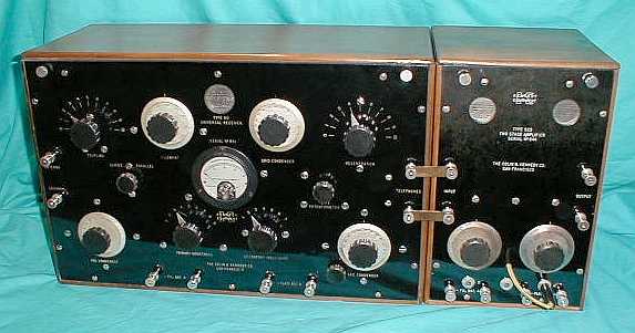
Colin B. Kennedy Co. - Type 110 - Universal Receiver Colin B. Kennedy receivers were the favorites of experimenters, radio enthusiasts and some hams. There were some commercial users, especially early broadcast stations where the receivers were used as emergency frequency monitors required by early regulations. Kennedy receivers were built to a high quality standard which meant a high selling price. The ultimate in quality and performance for the experimenter or radio enthusiast was the Kennedy Universal. It was so well-respected that it was still being sold in 1925 when most regenerative receivers were considered obsolete. Since the ad was in the April 1925 issue of QST, Kennedy probably believed that only the hams would be interested in a large regenerative receiver by that time. The Universal tunes from 25,000 meters to 150 meters (12kc up to 2.0mc,) which was just about everything you would listen to back in 1921, when it was introduced. A three circuit tuner operates the regenerative detector and a variometer controls the regeneration. Priced at over $300, it was certainly for the well-to-do. Kennedy 110 receivers were found in many early broadcast stations as emergency frequency (500kc) monitors. The 110 shown is SN 951 and the 525 is SN 644, both very early three digit numbers in the typical Kennedy-San Francisco style with nickel plated binding posts and the Plate Potentiometer adjustment. Performance on this functional example is first-rate and, in the 1980s, I won first place (regenerative receivers) in Radio Age's "Radio Receiving Contest" with this Kennedy 110/525 combination. One electro-mechanical necessity not found in any of the 1922 Kennedy receivers is any type of shielding. No panel shield or cabinet shields were installed on any of the Kennedy line of receivers. These were three-circuit regenerative detector receivers that could be used by professional radio operators to receive CW signals and that would require an oscillating detector to demodulate the signal correctly. When oscillating, the receiver's various controls all have EM fields associated with those controls. This results in severe "hand capacitance effect" when trying to tune or adjust the receiver. Most regenerative detector receivers installed panel shielding or control shielding to prevent "hand capacitance effects." Why a "high-end" receiver like the Kennedy line never installed any shielding is a mystery. Perhaps Kennedy believed their receivers would only be used for radiophone reception or for damped-wave (spark) transmissions. However, vacuum tube CW transmitters were becoming very popular in the early twenties and the Navy was using arc transmitters or Alexanderson alternators that also sent CW signals that required an oscillating detector for proper demodulation. The "hand capacitance effect" can be compensated for by tuning very slightly lower in frequency than the desired signal's frequency. When the hand is removed from the control, the received frequency will jump up slightly,...hopefully to the proper signal frequency (it takes a little practice but it does work,...sort of.) For the ultimate information source on the 1922 Kennedy Receivers and Audio Amplifiers, includes Colin B. Kennedy history and history of each receiver, operation of the equipment, restoration suggestions, correct schematics and interior photos of the equipment plus an article on Dr. Royal Rife's use of Kennedy equipment in his laboratory, see "Colin B. Kennedy - "Radio Apparatus of Quality" in the navigation index below. |
|
Colin B. Kennedy Co. - Type 220 - Intermediate Wave Receiver The Kennedy Type 220 Intermediate Wave Receiver and matching Type 525 Two-Stage Audio Amplifier made a very nice combination for either commercial use or for a well-to-do radio fan. It tunes from 3000 meters to about 150 meters, or about 100kc up to 2000kc, using a three-circuit tuner operating a regenerative detector. Early versions will have a Plate Potentiometer adjustment for controlling the plate voltage on the detector tube. The standard detector tube used was a soft-detector, the UV-200. The amplifier used hard-amplifier tubes, the UV-201. Kennedy receivers are usually described by the location of manufacture which was a chronological event and resulted in slightly different construction of the receivers. Early Kennedy receivers built in San Francisco will have nickel plated binding posts and plate potentiometers while later St. Louis versions have bakelite capped binding posts and no plate potentiometer. There are many other variations between the two versions and almost any example will differ from another in some small detail. This was due to the way that Kennedy equipment was built - all hand made. Though machines were used to make the various parts, since the machines were operated by hand, the resulting parts do have variations. Top quality was apparent with the silver plated dials on Formica panels that were machine engraved, all housed in a solid walnut cabinet. The 220/525 combination was introduced in 1921 and sold for over $200. In June of 1922, Kennedy was purchased by Wagner Electric and the operation was moved to St. Louis, Missouri. For the ultimate information source on the 1922 Kennedy Receivers and Audio Amplifiers, includes Colin B. Kennedy history and history of each receiver, operation of the equipment, restoration suggestions, correct schematics and interior photos of the equipment plus an article on Dr. Royal Rife's use of Kennedy equipment in his laboratory, see "Colin B. Kennedy - "Radio Apparatus of Quality" in the navigation index below. |
Colin B. Kennedy Co. - Type 281 - Shortwave Receiver Colin B. Kennedy was usually a builder of high quality home radios but if you were an affluent ham or experimenter, you might want to buy a Type 281 shortwave receiver with its matching Type 521 Two-Stage Audio Amplifier for your station. Using a standard Armstrong three circuit regenerative tuner, the 281 tunes from about 600 meters to about 150 meters, or about 500kc up to 2000kc. Most amateur operation in the early twenties was on 200 meters (1500kc and up.) The set uses a soft-detector (UV-200) and the amp uses two hard-amplifiers (UV-201) tubes. A solid mahogany cabinet and polished Formica panel are indicative of the quality and care that went into the building of Kennedy receivers. Introduced in 1921 and sold for $145. For the ultimate information source on the 1922 Kennedy Receivers and Audio Amplifiers, includes Colin B. Kennedy history and history of each receiver, operation of the equipment, restoration suggestions, correct schematics and interior photos of the equipment plus an article on Dr. Royal Rife's use of Kennedy equipment in his laboratory, see "Colin B. Kennedy - "Radio Apparatus of Quality" in the navigation index below. |
|
Wireless Specialty Apparatus Co. - RCA Radiomarine Corporation of America IP-501-A Receiver-Amplifier The IP-501-A was the classic shipboard wireless receiver. Its incredible performance, robust construction and high reliability made it the "standard" for all maritime receivers that followed for the next decade. It was developed from the Navy SE-1420 and later IP-501 series of wireless receivers. A three-circuit regenerative/autodyne detector is combined with a two-stage audio amplifier along with all the extra features that would be required for reliable communications at sea. Wavelength coverage is from 300 meters up to 7500 meters (1000kc down to 40kc, though most receivers tune from 1200kc down to 37.5kc.) The oak cabinet along with the back of the front panel is lined with copper sheet and and an extra copper shield isolates the Antenna Tuner from the Secondary Tuner for top-notch selectivity. Construction is heavy-duty, quality is first-rate and the performance is incredible. All screw and nut joints are soldered after tightening at assembly. This was to prevent anything from coming loose inside the receiver with the constant vibration encountered onboard ships at sea. The solder also protected the screw threads from corrosion. The earliest versions of the IP-501 family were built by Wireless Specialty Apparatus. However, many SE-1420 receivers were built under contract by AMRAD and by NESCO. From 1920 until 1923, all WSA IP-501 type receivers were sold by RCA since Wireless Specialty Apparatus, a company owned by United Fruit Company, was cross-licensed with the RCA/GE/Westinghouse Group. In 1923 or 1924, RCA was able to purchase WSA along with their manufacturing plant and began selling the IP-501 series built exclusively for RCA. In 1927, RCA combined WSA with another acquisition, Independent Wireless Company, to create Radiomarine Corporation of America. Radiomarine became a subsidiary of RCA and provided commercial shipboard equipment, operated the RCA coastal stations and handled the RCA Radiogram service. The IP-501-A receivers (and their variations) continued to be built up into the late-twenties, perhaps even later. Manuals were available as late as 1936. Most IP-501-A receivers were removed from ships just prior to and during WWII since their regenerative detectors easily coupled into the antenna tuner section and then up to the antenna. An oscillating IP-501-A could be received easily up to five miles away when operating at sea. The IP-501-A shown is the early version with Telephone Condenser switch and nickel plated binding posts. Later versions eliminate the TC switch and the binding posts use bakelite caps (these later versions have "Radiomarine Corporation of America" on the data plate indicating they were built after the 1927 creation of RMCA.) This particular receiver was originally used aboard the Matson Line steamship S.S. Mariposa. I have owned this IP-501-A for 45 years. A ham friend of mine traded a telephone pole for it and then sold it to me in 1979. I have performed three restorations on the set over the years, each one more complete and more original than the former one. The final restoration (in 1984) resulted in the receiver looking totally original inside and, of course, fully functional. It is a very sensitive receiver and, due to the full-shielding and stout construction, it's a very stable receiver. The calibrated wavelength dial is quite accurate - at least as accurate as you can be using wavelength, that is. For the ultimate information source on the SE-1420, IP-501 and IP-501A wireless receivers that includes history, construction, restoration and operation of these marvelous receivers and also includes "Tuning in NDBs with the IP-501A" including a NDB log of stations received (103 stations in 3 weeks time.) See "WSA & RMCA - SE-1420, IP-501 & IP-501-A - The Classic Shipboard Wireless Receivers" - use the Home Index link below. |
|
Radio Boulevard
Western Historic Radio Museum
Vintage Radio Communication Equipment Rebuilding & Restoration Articles,
Vintage Radio History and WHRM Radio Photo Galleries
1909 - 1969
- 60 years of Radio Technology -
This website created and maintained by: Henry Rogers - Radio Boulevard, Western Historic Radio Museum © 1997/2025