Radio Boulevard
Western Historic Radio Museum

Rebuilding the R-390A Receivers

Brief History - Assessing your Receiver - Disassembly

The Main Frame - The RF Module - The IF Module

The AF Module - The Power Supply Module - The PTO

Front Panel Restoration - Alignment - Performance

Miscellaneous Info on Variants and Accessories,

Restoration logs for:
R-390A built from Spare Parts, (2)1967 EAC R-390A Receivers
Collins R-648/ARR-41, Collins R-389/URR Detailed Restoration Log
Recreations of Arvin R-725/URR, ASA R-390A,
Clark AB Black Anodized Panel R-390A, USMC OD Panel R-390A


by: Henry Rogers WA7YBS/WHRM

     PART 1 - History, Assessing your Receiver, Main Frame, RF Module, IF Module, Audio Module, Power Supply, PTO, Front Panel Restoration, Meters


     PART 2 - Contractors List, Receiver Alignment, Expected Performance, R-390A Diversity Operation, Building a R-390A from Spare Parts, (2) 1967 EAC Rebuilds


      PART 3 - Recreations of Famous R-390A Variants: Arvin Industries R-725, ASA R390A, Clark AB Black Anodized Panel R-390A, USMC Olive Drab front panel R-390A


      PART 4 - R-389 Restoration WARNING! This write-up contains "Extreme ODC" detailed information and it's long, Rebuild-Dynamotor R-648/ARR-41, R-392 Info, Other R-390 Variants, Security Dial Cover, CV-979 Cabinet


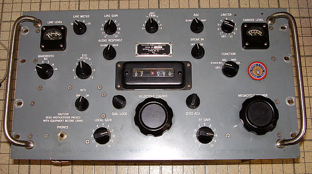
1967 Arvin Industries R-725

The R-725 is a R-390A that was modified by Arvin Industries to use a special-build Series 500 IF module that was an updated R-390 IF module (no mechanical filters.) Additionally, the R-725 has a ferrous metal shield installed over the PTO and a "hum bucker" addition that allows the PTO and BFO tube heaters to run on DC voltage. For the full story go to Part 3 of this article under "Creating an Arvin Industries R-725 Receiver."

PART 2

Other R-390A Details


The Contractor Companies, Contract Numbers, Build-Years and Production Quantities for R-390 & R-390A Receivers

R-390

1951  -  Collins Radio Co.  -  contract 14214-PH-51 (contract 14214-PH-51 was also used for R-389, R-391 and a quantity of 1027 R-390A receivers) 

1952  -  Motorola Inc.  -  contract 26579-PH-52

R-390A

1954, 1955  - Collins Radio Co.  -  contracts 375-PH-54 or 08719-PH-55  (1027 R-390As built on 14214-PH-51 contract)  '54 - 310 receivers, '55 - 4982 receivers

1955, 1956, 1958  -  Motorola Inc.  -  contracts 63-PH-54, 14-PH-56, 14385-PH-58     '54 - 3427 receivers,  '56 - 4909 receivers,  '58 - 6537 receivers

1959, 1960  -  Stewart-Warner Corp.  -  contracts 42428-PC-59, 20139-PC-60-A1-51   '59 - 2120 receivers,   '60 - 4511 receivers

1960  -  Electronic Assistance Corp.  -  contract 23137-PC-60 (may have been for modules only)

1961  -  Capehart Corp.  -  contract 21582-PC-61    4237 receivers

1962  -  Amelco Corp.  -  contract 35064-PC-62     3982 receivers   (Amelco was owned by Teledyne)

1963  -  Teledyne Inc. or Imperial Electronics Inc. - contract 37856-PC-63  3976 receivers  (some data plates show Imperial, others show Teledyne, who owned Imperial) 

1963  -  Stewart-Warner Corp.  -  contract DA-36-039-SC-81547 (may have been for modules only)

1966  -  Communications Systems Inc.  -  contract FR-11-022-C-4-26418 (this is an order number and have been for modules only)

1967  -  Electronic Assistance Corp. - contract DAAB05-67-C0115 (some data plates have the order number FR-36-039-N-6-00189(E) shown instead of the contact number)  
                                                           10,717 receivers plus 151 consumer (rocket tag) receivers

1968  -  Dittmore-Freimuth/EAC - contract DAAB05-68-C-0040    215 receivers built by Electronic Assistance Corp. for Dittmore-Freimuth

1984  -  Fowler Industries - contract N 00024-84-C-2027    5 receivers

NOTES:  The first 1027 R-390A receivers built by Collins will have long data plates with 14214-PH-51 contract number. This contract was used for R-390, R391 and R-389 receivers also. Remaining Collins R-390A receivers have short data plates with either 375-PH-54 or 08719-PH-55 contract numbers.

Shortly after Teledyne Inc. was formed, in June 1960, they purchased Amelco Corp. (they had invested in Amelco's initial start-up.) Imperial Electronics was also an early purchase by Teledyne.

Electronic Assistance Corporation was owned by the same conglomerate that owned Hammarlund in the sixties. It's often reported that Hammarlund owned EAC but Hammarlund, at the time, was owned by Guianini Scientific Corp. and Hammarlund Mfg. was located in Mars Hill, NC. The Hammarlund connection to EAC is vague, at best.

There are a few other contractors that were involved in producing R-390A receivers and modules but those listed produced the greatest quantity of receivers with Electronic Assistance Corporation building the largest number of R-390A receivers on a single contract at 10,717 and Motorola building the largest total quantity of R-390A receivers, although requiring three different contracts, ultimately producing 14,873 receivers.

It's generally believed that a combined total of at least 55,343 R-390A receivers were built by the various contractors.

Receiver quantities from: www.navy-radio.com

Ovens - Crystal Oscillator, PTO, Cal. Crystal - There really isn't a need to have these ovens operating. Maybe it was necessary when the receivers were operated by the military and were set up to copy enemy DFSK signals but today's amateur operations don't require that degree of frequency stability and the operation of the ovens increases the heat within the receiver substantially. To turn off the all ovens, look for the switch on the lower right corner of the rear panel. It's marked "ON" and "OFF" and to switch off just align the screwdriver slot of the switch shaft to be inline with "OFF." It's surprising how many R-390s and R-390As will be found with the ovens still operating. It's not necessary and just creates more heat and consumes power unnecessarily. A Note on All-Matching Modules - This is generally an indicator that the receiver has not been used extensively and has not gone through any sort of echelon rebuild. These types of receivers are desirable in one sense since they usually haven't been brutalized by careless technicians. Some enthusiasts consider the "non-matching modules" equipped R-390A to be inferior since it has obviously been worked on in the past. If you intend to use a R-390A "as delivered" then the all-matching modules type gives you a chance this "out-of -the-box" operation might be possible. However, if you intend to rebuild the R-390A before putting it into operation then the "non-matching modules" type usually will be a more reasonably priced option. All of the modules are basically the same regardless of which contactor built them. There are minor differences but they are all interchangeable and were designed to be so. You will find that the early Collins and Motorola IF modules don't have trimmer capacitor adjustments on the inputs and outputs of of the mechanical filters unless they've been upgraded with the 1956 MWO. The Engineering Change Order was issued in mid-1956 so no Collins R-390A will have the MF trimmers and the same for the first and possibly second contract Motorola R-390A receivers (this is for an "all original modules" receiver.) It might seem that the early Motorola RF coils are of a higher quality than the later EAC units (that normally used American Transformer units - but not always.) However, in early RF coils it's common to find a stuck rotor and stator on the trimmers. This isn't usually found on the later-manufactured RF coils. Early modules will have some paper dielectric capacitors. Late modules will have ceramic disks and polyfilm capacitors. These minor differences are just an evolution of production improvements in most cases. The contactors had to meet a detailed specification when building each module and all modules will perform to spec after a rebuild and alignment (if required.) Because of these specs, all modules are interchangeable regardless of which contractor built the module. Certainly, if you enjoy the rebuilding process, then a "non-matching modules" R-390A will be your most economical route and you won't have to be concerned about disturbing the unit's originality. However, now at 50+ years old, even the all-matching 1967 EAC R-390A receivers should be thoroughly checked over before operating.

"Blue Stripers"

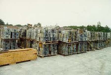
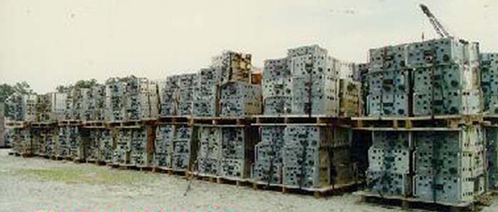
When some of the military R-390A receivers were decommissioned, they were sent to a facility located in Portsmouth, Virginia called St. Julian's Creek Annex. At this repository, thousands of derelict R-390 and R-390A receivers were piled one on top of another and stacked side by side on pallets. The receivers typically had their meters removed (due to the radium used on the needles and the scales) and usually the data plates were also removed. Many times the top and bottom covers were already missing. Sometimes receivers were found that still had their meters installed. The story goes that the meters were checked for radiation levels and removed if the reading exceeded a predetermined level. If the radiation level was below the spec then the meter was usually "tagged" with a stick-on paper dot. The final indication that the receiver was "ready to scrap" was to brand it with a "blue stripe" that was generally applied from a spray paint can. Many times, yellow paint was used but the primary use of blue paint has accounted for the nickname - "Blue Striper."

The St. Julian receivers were left out in the weather with no protection whatsoever. The receivers that were in the middle of the vertical stacks generally faired best while the receivers at the top of the pile got all of the rain, snow, sun and dirt and the receivers lower in the pile got all of the debris "run off." The duration of the storage depended on when certain pallets were sold off. At one time, the receivers sold for as little as $37.50 per receiver, taking into account the entire pallet had to be purchased. Usually a pallet contained 12 receivers. Apparently, over the years, R-390As came and went at St. Julian's Creek Annex. Some receivers may have been sold in small lots but the majority were sold by the pallet. It appears that well into the 21st century, R-390A receivers were still being sold from St. Julian's Creek.


St. Julian's Creek Annex - piles of R-390As

It's difficult to tell how deep the pallets go (at least four deep) but they're all double-stacked


Another View of St. Julian's Creek Annex

12 receivers are strapped to each pallet. There are 216 receivers just in the front row of pallets and more behind that

Some of the R-390A receivers sold by Fair Radio Sales in Lima, Ohio were "Blue Stripers" from St. Julian's Creek Annex. The Fair Radio Sales' "Blue Stripers" were the ones that were sold as "needing some work" - maybe a bit of an understatement. Selling price was an incredible $330 in the 1990s. It's generally thought that Fair Radio Sales would put together the "needing some work" R-390As from various condition "parts sets" and "used spares." Consequently, most (if not all) Fair Radio "Blue Stripers" are not true St. Julian's Creek R-390As and probably only have some parts that came from the annex.

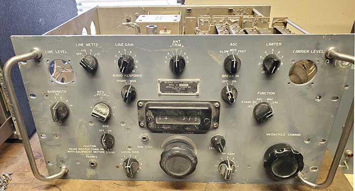
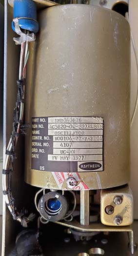
The R-390A "Blue Striper" shown above was sold by Fair Radio Sales many years ago and, after its purchase, it sat for many more years in a garage in the San Francisco Bay Area. It was donated to WHRM in 2011 by NU6AM. Note that the panel was repainted a non-original very light grayish-white and the nomenclature has been filled in black. Additionally, this receiver has a Raytheon PTO dated 1977. I would think that this is probably a Raytheon rebuild of a Cosmos PTO. Overall, the condition of this "Blue Striper" is surprising good (well,...not that good.) Of course, none of the modules match (contractors) which seems to confirm that Fair Radio did "put together" this receiver from parts. What is odd is that Fair Radio would go through the trouble to assure that relatively good condition modules were provided and then use a "Blue Striper" front panel. Also, as expected, this "Blue Striper" is non-functional.

"Blue Striper Fate"

Update 2013: Unfortunately, like a lot of receivers in the condition that this "Blue Striper" is in, this one has become a source of parts to restore other R-390A receivers that have faired better. The RF deck has gone into a 1962 Teledyne R-390A. The IF module has a bad 4kc mechanical filter but may donate other parts to repair other IF modules. The PTO may go into the 1961 Capehart (but didn't, it ended up in the Imperial "built from parts" R-390A) The ON/OFF microswitch went to repair an Amelco R-390A. It's unfortunate but parts are what keep other R-390A receivers in "top condition" so they can be operated and appreciated for the impressive performance they can provide the user/owner.

Update 2022:  In 2022, I rebuilt a Capehart IF module and used the 8kc and 16kc mechanical filters and Z503 from the "Blue Striper" IF module (it's really a wreck now.) The "Blue Striper" front panel also was harvested for several mechanical parts for the Capehart OD panel rebuild in 2022. At the end of 2022, The "Blue Striper" made the final sacrifice by donating its entire Main Frame for the "R-390A Built from Parts" project. The only part now left is the front panel (minus all of its component parts.) "Parts sets" are a very important and an almost absolute necessity when restoring incomplete or challenged R-390As. 


R-390A Receiver Alignment - Miscellaneous Info

Initial Power-up after Rebuild  You should have the R-390A receiving stations on all bands with power on. You can turn on the CAL and the BFO. Then tune to a 100kc calibration signal. Now rotate the MC knob through each of the bands listening for the calibration signal. Normally, you'll hear the CAL signal on every band although it will be at various tone-frequencies depending on each band's particular alignment at this time. You should hear the signal on every band though. This will assure you that everything is basically working and the receiver is responding to an input signal on each tuning range.

Things to do Before Proceeding to the Fixed-IF, Variable-IF and RF Alignments - you should first do your PTO end-point error correction, if necessary (it will be.) Be sure that the Calibration Oscillator is set correctly and the Veeder-Root counter is in sync with the PTO (you should have checked both before doing the EPE adjustment.) Also, check the Crystal Oscillator output at E-210 and be sure the voltage there is between -3.5vdc and -8.0vdc on the 8mc to 31mc tuning ranges. The voltage should appear when the MEGACYCLE knob is on its detent for each band and remember that the receiver must be in Stand By for this test. You don't have to check the .5mc to 7mc bands because these crystals and associated oscillator circuits are both fundamentally and harmonically operated and also work in either a double or triple conversion scheme. They were actually checked in the higher ranges. Be sure your DIAL ZERO is mechanically centered within its approximately one-sixth turn of the KILOCYCLE tuning when calibrated to any XX.000 (or any 100kc marker) on the Veeder-Root counter.

Error in Army TM 11-5820-358-35 and more - Field Depot and Maintenance Manual for the R-390A from December 1961. Alignment instructions, page 116, paragraph 76b (2) indicates that URM-25 Signal Generator should be tuned to 18.75mc. Actually, the correct frequency is 18.25mc. This error was very obvious to technicians doing the alignment and is very well known. Interestingly, the earlier TM 11-856A Technical Manual for the R-390A has the correct 18.25mc information, so this later error was probably a typo that wasn't caught in proof-reading. There are many conflicts in the Army TM schematics due to the reluctance of the Army to change the schematic. Instead "NOTE" is placed on the schematic that should guide you to a list of upgrades that changed the schematic or component value. Just be aware that if you're troubleshooting to the component level to double-check if a circuit value is in conflict with what is shown on the schematic.

How to do the Balanced Input Alignment - Make up a test resistance that consists of two 68 ohm 1/2 watt carbon resistors in series. Each separate leg of the resistors will push into to each terminal of the Balanced Input Twin-ax connector. The junction of the resistors will be connected to the signal generator. When performing the alignment of the RF stages first adjust the Balance trimmer on the the RF transformer for the minimum voltage on the DIODE LOAD as read on an (analog) VTVM. The Balance adjustment will not reduce the DIODE LOAD voltage to zero - you're setting the Balance trimmer for the minimum voltage. Be sure the ANT TRIM is set to 0. With the minimum voltage set, now proceed with the RF adjustments for that section of the receiver. Recheck the Balance trimmer adjustment after the particular RF section has been aligned. The Balance should still be close but will probably need just a slight adjustment for minimum voltage at the DIODE LOAD. Recheck the RF alignments - but there should be no significant change and just a slight "tweak" should be all that's required.

Does it Really Matter - Balanced or Unbalanced Input? - If you do the Balanced Input alignment, then the answer is yes. Correctly aligned you might see an improvement if you are using an adapter that grounds one side of the two terminals and connects an unbalanced antenna (that is matched for the received frequency) to the other terminal. This method runs the signal through a set of tuned coils before going to the RF amplifier stage. If you haven't performed the balanced alignment then it's very possible that a reduced signal level may be experienced with this method of connecting the antenna. In this case, connect your antenna to the Unbalanced input (but, eventually, you'll want to do the Balanced Input alignment.) Originally, the Balanced Input was for dipole antennas that used a balanced feed line in the 100 Z ohm range utilizing the "twin-ax" type coaxial cable. Nowadays, hardly anyone runs a balanced antenna directly since most transmitters operate into unbalanced loads. Additionally, the "twin-ax" type cable has a significant db loss per foot. If you're using a tuned antenna with antenna coupler, you might find that the Unbalanced input works better. This may also be the case if you're using a vertical antenna directly fed with coax. Go ahead and do the balanced alignment and then test both Balanced and Unbalanced inputs to see which nets the best results for your particular antenna.

Stagger Tune the IF or Peak Adjustment of the IF? - Stagger tuning will give the IF bandwidth the maximum flat top possible with the mechanical filter selected. Early receivers were "peak" tuned for maximum response and may give a frequency bandwidth somewhat less than the mechanical filter bandwidth. Stagger tuning was used on the later IF modules and does give a better response in the receiver that is generally flat out to the limits of the mechanical filter's bandwidth. You can align early IF modules using the Stagger Tune method. Be sure to check the IF transformers to verify that the Q-spoiler resistors are present. Some IF transformers were modified by clipping out the Q-spoilers to have more IF gain but this also narrows the bandwidth. The Q-spoilers should be installed and connected for the best bandwidth. Updates to TM11-856A have the later procedure for stagger-tuned IF alignment, as does TM11-5820-358-35, or it can also be accessed from many sources on the Internet.

IF Cans without the Alignment Hole - Early production IF modules will have shields over the IF transformers that don't have a hole for alignment. This was to assure that the receiver's IF alignment wasn't tampered with in the field. When the receiver went back for repair or alignment the technicians had a set of covers with holes that were installed for the alignment and when the alignment was finished then the "non-hole" originals were re-installed. If you can't locate an extra set of IF cans then it will be necessary to drill an access hole for alignment. All later IF shields had the hole anyway and many early ones are found nowadays with the hole already drilled since the TM directs the technician to drill a hole for alignment purposes.

Slug and Trimmer Adjustments - One caution on adjusting the slugs and trimmers for the RF alignment. First set the Veeder-Root counter on the R-390A to the specified frequency. Then set the RF Signal Generator to its specified frequency. You'll notice that by "rocking" the Signal Generator frequency that there is a "peak" output on the Diode Load that is very slightly different from the Veeder-Root counter setting. Be sure to use the "peak" Diode Load voltage set by the Signal Generator frequency adjustment. Once you've set the signal generator to have the peak Diode Load voltage, then adjust the proper slugs or trimmers for further maximizing of the Diode Load voltage. Remember, the slug adjustments don't affect the receiver's frequency readout accuracy. That's a function of the PTO accuracy and the Crystal Oscillator. Always set for the "peak" response by "rocking" the RF Signal Generator and then adjust that band's slugs and trimmers for maximum output on the Diode Load.

What to do about early IF modules without the Mechanical Filter trimmer caps? - The trimmers were added with the 1956 contract R-390A receivers. The earlier IF modules will have fixed-value 110pf mica capacitors to tune the input and output of each mechanical filter. When checking these earlier IF modules, it will be necessary to measure the output  and see whether or not each of the Bandwidth positions (16kc, 8kc, 4kc and 2kc) are more or less equal for a constant, known-value input signal. The easiest way is to use the CAL and tune to zero beat and watch the CARRIER LEVEL meter. For instance, if 16kc and 8kc measure 50db on the meter but 4kc measures 40db and 2kc measures 50db, then something is wrong with the 4kc mechanical filter. When doing this test, you'll notice that the fixed tuned mechanical filters are not equal but are usually fairly close - spec was within 5db of each other. If the four filters are not close in their equal response it will be necessary to reselect the tuning capacitors on the filter that is different (hopefully, it's only one filter that has been affected.) Try to select capacitors so that each Bandwidth position results in a fairly equal output in all four Bandwidths (mechanical filter derived bandwidths, that is.)

Make up an adjustable trimmer that has a range of about 80pf up to around 130pf. Remove the cover from the mechanical filters on top of the IF module and then remove the 110pf fixed capacitor on the particular mechanical filter. Now "tack solder" the trimmer in its place. Power-up the receiver and select the bandwidth for the particular mechanical filter and adjust the trimmer for maximum reading on the CARRIER LEVEL meter. Remove the trimmer and measure the capacitance with a digital capacitance meter. Install a silver mica capacitor of that value to the mechanical filter. This may be enough to get the mechanical filter tuned enough for equal response but it usually isn't.   >>>

>>>  To do the capacitance selection for the mechanical filter output will require accessing the underside of the IF module. You can loosen the BANDWIDTH and BFO knob-shafts and pull them forward. Then undo the IF OUTPUT coax cable and loosen the three captive screws. The IF module can now be lifted in the front and placed in a vertical position. Use rubber spacers to "prop up" the IF module. Remove the fixed silver mica on the particular mechanical filter and "tack solder" the adjustable trimmer. Power-up the receiver and switch the BANDWIDTH control for the particular mechanical filter and adjust the trimmer for maximum reading on the CARRIER LEVEL meter. Remove the trimmer and measure its capacitance and install that value silver mica on the mechanical filter. Replace the IF module and the knob-shafts and give the receiver a final test to see how the new tuning compares. Hopefully you'll be able to retune the mechanical filter to be within 5db of the other mechanical filters. Needless to say, the 1956 upgrade that added adjustable trimmers to all of the mechanical filters made everything a lot easier.

NOTE: Most handheld digital capacitance meters aren't even close for accuracy when measuring pico-farads. Not to mention that, at the pf scale, the test meter leads will also add significant C (some meters have a zero adjust but still the accuracy is limited.) It makes this sort of fixed-value tuning extremely difficult to do accurately. Unless the input/output fixed C is way off, it's probably better to just leave the MF tuning "as-is." The spec was within 5db of the other MFs. It would have to be over 10db before I'd try this method of retuning the MF. And,...actually an easier approach is to install the MWO for adjustable trimmers - well, actually just use an IF deck that already has the MWO, then just test and install. Keep the original IF module around just in case for some reason you want an "all original modules" R-390A.


Expected Performance

I've used many R-390A receivers in my various ham radio and vintage military radio station set-ups over a period of many years. My first R-390A was a 1959 Stewart-Warner version that worked pretty well "as-is" when I got it from a ham swap meet in 1991. I used it with an Eldico SSB-100F transmitter I had and performance was great. A few years later I obtained an excellent EAC version from 1967 but I sold it to buy a 1951 contract Collins R-390 installed in a CY-979 cabinet. I still own and use the R-390 on a regular basis. I sold the 1959 Stewart-Warner after obtaining a 1955 Collins R-390A. This Collins R-390A was given to me as payment for repairing and rebuilding a Motorola R-390 for a fellow ham. Eventually, I "wheeled and dealed" my way into a 1956 Motorola R-390A, a 1961 Capehart R-390A and a "Blue Striper" survivor from St. Julian's Creek Annex. In 2016, a bargain-priced 1967 EAC was purchased. It needed a little TLC and turned into a great receiver. Another '67 EAC showed up at a bargain price in 2017. In 2019, I traded some BC gear to a fellow collector for his entire stock of R-390A parts sets and modules. From that collection I was able to recreate an original Arvin Industries R-725 (R-390A with R-390 IF deck.) I've used all of these receivers except the "Blue Striper" at one time or another, both as an SWL receiver or as a Station receiver.

Here's what I like about the R-390A,...

1. If you absolutely must know exactly where in the electromagnetic spectrum you are listening, the R-390A and its family are the most frequency-accurate readout available in vacuum tube receivers. It's easy to achieve 1/2 kc accuracy or better. The mechanical-digital readout eliminates the vague interpretations of reading analog dials.

2. If you think you're going to be bothered by QRM, remember the R-390A was designed to intercept radio signals from the USSR, China, Cuba, East Germany and other Communist countries and to be able to successfully copy those signals through any kind of interference whether natural or man-made. The R-390A also provided reliable communications, including mobile RTTY, despite jamming efforts from some of our Cold War adversaries. The receiver can cope with just about any type of amateur interference since it was designed to work through "professional-level" QRM.

3. When the R-390A is rebuilt and correctly aligned it is very competitive as far as sensitivity is concerned. Are there more sensitive receivers? Of course. But sensitivity isn't all that's required to successfully copy weak signals. Nowadays, the ability of a receiver to function well in a noisy EMI environment is far more important than an "under a microvolt sensitivity" spec. After all, when your local EMI noise floor is a constant S9, what good is .25uv sensitivity? When all the available controls are taken into account along with the mechanical filter selectivity (and the user is very familiar with the operation and capabilities of the receiver) the R-390A is almost unbeatable as a station receiver.

4. Stability is the best in vacuum tube designs. Drift is non-existent.

5. You have two individual audio outputs on an R-390A. The LOCAL AUDIO is normally used to drive a 600Z ohm speaker set-up but you can also use the LINE AUDIO for the same thing - simultaneously! The LINE AUDIO was normally used to drive data devices like RTTY TUs, etc., but there's no reason it can't drive any 600Z load - like another speaker. I've set up a speaker in one room run by the LINE AUDIO and a second speaker in another room run by the LOCAL AUDIO. Independent audio levels in separate rooms. Really neat.   OR,...if you just want to utilize the LINE LEVEL meter to show a response to the audio component of the signal then install a 680 ohm 1/2W resistor across the LINE AUDIO terminals. You can now turn on the LINE GAIN and select the LINE METER scaling and the LINE METER will respond to the audio component of the received signal.

6. Everything about the R-390A's construction is "heavy-duty" and its use metal knobs imparts a massive "feel" to the receiver's operation. The R-390A has a certain impressive presence that attracts the attention of ham shack visitors. This seems to be true whether the visitor is familiar with the R-390A receivers or not. 

The following might be concerns for some users,...

1. On SSB and the Meters - Although there were a couple of military SSB adaptors , the CV-591A (aka MSR-1 or MSR-4) and the CV-157, available and several modifications have been published and other add-on devices available for demodulating SSB produced, none of these are necessary for receiving undistorted SSB signals. Unfortunately, many new R-390A owners have only used modern equipment (with SSB Product Detectors) before going to the R-390A which only has a simple Envelope Detector. They expect the R-390A to be adjusted for SSB reception just like their modern receiver - RF GAIN at maximum with the AVC (AGC on the R-390A) on and volume level set by the AF GAIN (LOCAL GAIN on the R-390A.) The R-390A can't be operated like that when receiving CW or SSB. Before product detectors came along it was standard procedure when receiving CW or SSB to reduce the RF GAIN and advance the LOCAL GAIN (AF GAIN) so that the proper ratio of incoming signal to BFO injection could properly demodulate either CW or SSB. AGC was usually turned off but it depended on the receiver design. With the R-390A, AGC can be left ON to limit the maximum response, if desired. If the R-390A's BFO is properly set-up, its position allows selecting either upper or lower sideband. Now, you do lose the function of the CARRIER LEVEL meter (and most AGC action) in this method of reception but who cares? The CARRIER LEVEL meter measures DB over 1uV and its accuracy depends on the RF GAIN setting. If you were planning to use the CARRIER LEVEL meter for CW or SSB signal reports, most stations wouldn't even know what you're talking about when your report was so many "db over 1uV." It's all a relative measurement anyway, dependent on the frequency and conditions. It's better to operate the R-390A as a standard pre-product detector receiver for CW and SSB and just give your contacts an estimated R-S-T report.

2. More on the subject of SSB reception and Modifications - The CV-591A family of SSB adapters were built by The Technical Materiel Corporation. These adapters work from the IF output, therefore you lose the Noise Limiter function, the 800 cycle filter function and the dual audio section of the R-390A receiver if you utilize only the audio output section of the CV-591A. Now, if you happen to have an extra speaker, you can connect one to the CV-591A output (8.0Z or 600Z) and the other one to the R-390A's LOCAL AUDIO (600Z only.) If you want to do SSB or CW you can use the CV-591A and its speaker. If you want to do AM, then use the R-390A's LOCAL AUDIO and speaker. The CV-591 will provide excellent, distortion-free SSB reproduction and they are well-worth using. The only disadvantage is the price that the CV-591A is fetching today, sometimes selling for more than the R-390A receiver. 

On modifications to enhance SSB reception,...most of the mods that have been published do not improve the receiver's overall performance. Most modifications on any piece of vintage radio equipment will enhance performance for one area at the expense of overall performance. Besides, modifying a vintage receiver to make it operate like a "modern" piece of equipment seems to go against the whole idea of collecting, restoring, operating and preserving these classics in the first place. You're better off to learn how to use the R-390A properly and when you do, you'll find that modifications are not necessary for great performance in all conditions and in all modes.

3. On Audio Quality - Audio reproduction is not as bad as a lot of "BC-Quality AMers" complain it is. The mechanical filters provide a specific, very steep-sided bandwidth but some AM op-listeners are used to the "bell curve" that many early vacuum tube receivers had with only two fairly broad-tuned IF amplifiers. "Ringing" or a "hollow sound" were the usual complaints about the mechanical filter bandwidth. If you change the LOCAL AUDIO coupling capacitors to .022uf and then use a high quality 600Z transformer with a large speaker in a good enclosure, the audio sounds very nice, especially in the 8KC bandwidth (which is really close to 11KC) on AM with marginal signals or 16KC with a really great signal level (AM or SW Broadcast but it's hard to find quality program material being broadcast.) You'll have to do the same thing to the LINE AUDIO if you want to run dual audio lines to two separate speakers. However, if you're really into high-fidelity, then you can take the signal from the DIODE LOAD and run it through a shielded cable to a high-fidelity audio amplifier that's connected to a large hi-fi type speaker system. At 16kc bandwidth, AM signals will sound incredible. As with the SSB adapters though, you'll lose the NOISE LIMITER and 800 cycle audio filter functions with this "hook-up" unless you provide a separate speaker on the LOCAL AUDIO line (just in case you want to do CW.) For most users though, especially if you're using typical communications loudspeakers, the stock audio sounds pretty good and the original .01uf coupling caps are fine. I've only substituted the .022uf on a couple of R-390A receivers (and that was done years ago) and it's difficult to tell the difference between those receivers and the ones with stock coupling caps.

Here are some disadvantages to using the R-390A  -  minor stuff, really,...

Break In Operation - The R-390A "Break In" function requires using a T-R relay with Normally Open (NO) contacts that change to Normally Closed (NC) when in transmit. This function operates the R-390A Break In relay and the R-390A Antenna Relays. The Break In function of the R-390A is opposite that of a typical receiver Stand By function that will require the T-R relay to provide a NC state for receive and NO for transmit. Most T-R relays, like the Dow-Key type, will usually provide a set of DPDT auxiliary contacts that allow connecting the R-390A Break In to one of the NO set of contacts. Most vintage military transmitters will have internal T-R relays that provide receiver antenna switching and also NO and NC contacts on the sending relay to control the receiver standby. Use of the Break In function is essential to protecting the R-390A's input circuitry. The Break In function totally isolates the receiver's input using relays to disconnect the antenna line and ground the receiver input. If the Break In isn't used and there's a failure within the T-R relay, full transmitter power might be fed directly into the receiver input. This failure mode is more common than one would think and shows up as a burned primary coil on (most commonly) the 2-4mc ANT/RF transformer (since most ham-use of R-390As is on 75M.) If there are no auxiliary contacts available for proper operation of the Break In, one can jump the Break In terminal on the back panel to ground. Then use the Break In switch (ON-OFF) on the front panel for the Stand By function. The same sort of isolation does happen when the Function switch is used for Stand By but using the Break In is the proper method for placing the R-390A in "stand by" during transmit.

The Weight Issue - No doubt, the R-390A is a heavy receiver weighing in at close to 85 lbs. Here's a hint for when you have to move the receiver. Remove the Power Supply module and the AF module. These two modules will reduce the weight by close to 20 lbs. With the covers off and the two modules out, the receiver weighs about 65 lbs - much easier to move. Of course, you still have to get the receiver to the work bench to remove the covers and modules (use a roll-cart.) This hint is really for moving the receiver longer distances, like to another room, ESPECIALLY when the moving involves going up or down stairs.

Cabinets - If you want the R-390A to be mounted in a cabinet you have two choices. First, is to find the proper CY-979 (or CY-979A) aluminum cabinet. This is a high-quality, military cabinet that is designed for the R-390-family of receivers. They are expensive. Originals were built from the early fifties up well-into the sixties. In the 1990s, an ad in Electric Radio offered CY-979 cabinets for about $150-$200. These cabinets were restored by W5MC and ink-stamped on the interior with an ID. There is some confusion on these restored cabinets as it wasn't clear in the ad if these cabinets were rebuilt old ones or new recreations. It doesn't seem likely that someone could have built a CY-979A complete with shocks and skids and then sell it for so little. But, since any original contractor ID was removed in the restoration process, the only ID is the ink-stamp inside which usually has a date with it (from the 1990s.) I've only seen one of these W5MC CV-979A cabinets and it was exactly like the original, with the screens inside the louvers, proper shocks and skids, etc. I would have to conclude that these W5MC cabinets are "restored" originals. If you are going for the CY-979 cabinet and you're willing to pay a high price be sure that the one you decide on has the shock mounts and the skids. It's fairly common to find CY-979 cabinets with the shocks and skids removed. These modified cabinets are incomplete and should be priced accordingly. For more details on the differences between the CY-979 and the CY-979A, go to the section on these cabinets at the bottom of the page in Part 4 of this write-up. Other than the CY-979, any other cabinet that is for 10.5" by 19" panels with a depth of 15" will also work. Several sources sell a new Hammond cabinet of this size. Although advertised as a "R-390A Cabinet" it really is just a cabinet in which the R-390A will fit. Price is several times less expensive than the CY-979.

 
Quick Check for Prospective R-390A Purchases -  The following "Quick Test" assumes you are at the seller's QTH and have AC power available. The test doesn't require anything other than the powered-up R-390A and can be used for any R-390 or R-390A receiver that you are interested in purchasing. Hopefully the seller will allow this easy test since you don't need an antenna (a common excuse from sellers for not providing information is lack of an antenna.) Though a loudspeaker connected to LOCAL AUDIO would help, you don't actually need a loudspeaker but make sure both LOCAL and LINE gain controls are set to "0" if a speaker (600Z ohm load) isn't connected. If you bring your own 600Z ohm speaker, if the seller is agreeable, connect it to the receiver LOCAL AUDIO terminals.

Put on the CAL and the BFO, set the KC to xx.500 kc and rotate the MC change thru all bands to hear if the CAL oscillator is received on all bands. Turn off the BFO, make sure the RF Gain is fully advanced, AGC is selected and then, watching how much the CAL oscillator shows on the Carrier Level meter, run thru the bands again. The meter level should read over 40db. 50db is more likely if everything is aligned. Be sure to check all bands for CAL Carrier Level. With the CAL still on, check the EPE on any band. You should switch the Bandwidth down to 1kc for better accuracy. Be sure to also check the linearity every 10kc. That's an easy test that shows a lot. Recent alignment should have no more than 0.5kc EPE and an unknown PTO might have up to 4kc EPE but should still be linear with just a slight change each 10kc increment. These two tests are easy to perform and tell you a lot of info. If both tests look good, the receiver is probably in good shape. This applies to any R-390A that you want to perform a "quick check" to.

Since the CAL oscillator is practically connected to the Antenna Input, it serves as a onboard signal generator. If you hear the CAL oscillator when tuning through the 100kc markers on all bands (if you have a speaker connected,) then most of the receiver is working well enough to receive a strong signal. The reading on the Carrier Level meter will show generally how sensitive and in alignment the receiver is. Most rebuilt and aligned R-390As will show 50db+ on the meter at around 10mc. Check around 5mc and the meter should read the same or slightly higher. Check around 15mc and the meter will probably read less but still be around 40db. The EPE check just tells you if the receiver has been recently aligned by someone who is thorough and did do the EPE adjustment. EPE < 1kc, recent alignment. EPE > 4kc, typical of "as found" PTO.

You never know how a seller is going to react to this testing, so before doing any testing, be sure to describe what you want to do, what you're going to be looking for and why. Most honest sellers would welcome more detailed information on what they're selling. However, many sellers will react to this testing as a "haggling method" and become suspicious of your motives. If the seller has technical ability, they'll usually understand the testing and the results. If the seller doesn't even know what the R-390A is other than something to sell,...well, not much can be done in that situation. Actually, when dealing with non-technoid sellers, you're trying to access the condition of the R-390A for your own motives and from that information judge if it's priced accordingly. If it's priced fairly for its condition, then buy it. If it's not fairly priced,....well, all of the haggling efforts are usually a waste of time when dealing with the non-technical type of seller.


Dual Space Diversity Operation with the R-390A Receivers

If you're lucky enough to own two R-390A receivers and have room for widely separated antennas, you can easily set up the pair to operate in Dual Space Diversity. Good separation of the antennas would be at least one wavelength at the frequency of operation but usable diversity effect can usually be obtained with closer spacing if necessary. Space Diversity assumes you will be using two similarly polarized antenna and are relying only on the phase differences of the radio wave based on the spacing of the antennas. You can also try "Polar Diversity" which relies on a vertical antenna for one receiver and a horizontal antenna for the second receiver. Polar Diversity doesn't require that the two antennas be separated by great distances and assumes that there will be a benefit from the reception of two different polarizations of the incoming radio wave. This assumes that some splitting and rotation of the radio wave will occur as it propagates through the ionosphere and is returned to earth. Generally, space diversity helps with fading signals and polar diversity helps with phase distortion due to wave rotation. 

With either method of Dual Diversity reception, the receiver set-up is the same. You will be connecting the DIODE LOAD from each receiver together. The receiver that you plan on operating as the "master" will have to have the DIODE LOAD terminals jumped while the "slave" receiver doesn't have the terminals jumped. The "slave" receiver is only operating to the detector stage and its audio output is not used. You can connect 500 ohm resistors across the LINE AUDIO and the LOCAL AUDIO on the "slave" receiver. You will also have to install the jumps to connect AGC DIV terminals together on each receiver. You will also have a wire connecting the AGC DIV from each receiver together. A speaker on the LOCAL AUDIO is only required on the "master" receiver.  To listen to just the "slave" receiver, turn the RF GAIN on the "master" receiver to 0 and what you hear thru its speaker is the "slave" receiver. Also, if you want to listen to just the "master" receiver, turn the "slave" receiver's RF GAIN to 0 and what you hear thru the speaker is the "master" receiver only. With both receivers operating and connected to their respective antennas, tune in a strong shortwave broadcast signal. Have both receivers' RF GAIN set to about 8. Don't set the RF GAIN on either receiver to "full on" (10) or each receiver will "fight" the other one for control of the AGC line. By alternately reducing the RF GAIN of each receiver to 0 you should be able to end up with both receivers tuned exactly to the signal. Once the SW BC signal is tuned in on each receiver you will need to "balance" the RF GAINs. Slowly increase the RF GAIN on the each receiver alternately to the point where you see the CARRIER LEVEL meter showing some response. Adjust the RF GAIN on each receiver until you have the highest CARRIER LEVEL readings on each receiver without one receiver or the other "overloading" the AGC line. When "overloading" occurs the CARRIER LEVEL meter on one receiver will drop much lower in its reading and with a reduction in the RF GAIN of the other receiver you'll see the meter reading jump back up. By "balancing the receivers" you get the best diversity response and the best sensitivity. You will note that the two receiver's CARRIER LEVEL meters will react differently since each receiver is responding to a phase difference in the radio wave based on the separation of the antennas. You should see deep fades that cause one CL meter dip while the other receiver's meter remains steady. You should also see a reduction in phase distortion if you are using the polar diversity set up.

Remember, you can only use AM reception on this type of Dual Diversity. That's because CW or SSB reception requires the BFO to be in operation and the BFO dominates the detectors and spoils the diversity effect. For RTTY reception special TUs were used like the CV-116 that was designed for diversity RTTY. Diversity CW reception required Tone Keyers.

So, give Dual Diversity reception a try if you can. It's interesting and sometimes beneficial to copy. 

 
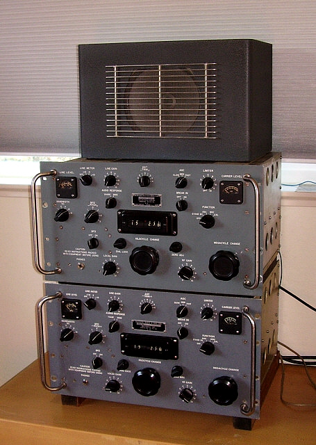
photo above
: A Dual Diversity set-up with the 1956 Motorola on the bottom and the 1955 Collins on top. Both receivers are fully rebuilt (including recapping) and both are fully aligned. Though the speaker looks like a Hallicrafters PM-23, it isn't. It's a homemade wooden cabinet that houses an 8" Jensen speaker and the louvers are made of aluminum. The cabinet is painted gray wrinkle finish.


R-390A Receivers and Variations
Rebuilding, Refurbishing and Recreating Projects


New for 2022                                                     Building a R-390A from Spare Parts   (2022)  

I'm starting the Rebuilding write-ups with this latest 2022 "parts set" project because it really doesn't involve a specific contract receiver. Rather, it shows the steps necessary to transform a collection of parts to a nice-looking, functional receiver. For many R-390A rebuilders, this is standard operating procedure since the majority of reasonably priced receivers will have gone though depot repair many times during their military service and no longer have any of their original modules. The object of this "Frankensteinesque Creation" (well, it is put together from parts scavenged from the boneyard of derelict non-operating receivers) is to illustrate that any of the modules and any of the parts are interchangeable by design and, regardless of contractor, any operational (and aligned, if necessary,) module can be used as a replacement in any working and aligned receiver and that receiver will function to specification. This project relied heavily on my collection of R-390A spare modules and "parts sets" along with many boxes of used hardware - the so called "junk boxes" that I've been gathering over the years,...decades actually.

Getting the All of the Parts Together - I ordered a set of R-390A meters from Bandit35 from eBay. He was closing his R-390A parts business and was selling everything at discount. The meters were less expensive than what I usually had seen, so they've been purchased.

Nov 27, 2022 - I got the Imperial R-390A down from the top shelf in the storage area. It's missing all of the modules except for the RF module. All front panel controls are present along with their correct knobs. Both tuning knobs are present. The Veeder-Root counter looks good and the dial cover is in pretty good shape. The Main Frame is a little "beat up" with some minor bends that should be easy to straighten. Back panel looks complete. All harnesses look good with the proper connectors (not exactly. I sure didn't look very closely at this Main Frame at this time.)

The front panel has a "fat finger" ring around the Kilocycle knob, BUT, I have an excellent condition front panel that is going to be used for this project.

Since Imperial Electronics was owned by Teledyne and Teledyne also owned Amelco, I think it will be acceptable to use Amelco modules in this Imperial R-390A. I've found the Amelco IF module - it wasn't with the other parts-modules but was upstairs in a back storage room. It looks in very good shape. I selected the best of the two Amelco Power Supply modules I had. I've also pulled an Amelco AF module that has "GOOD" written on the side but is missing the "plug-in" filter caps. I'm going to check the Raytheon labeled PTO that was installed in the "Blue Striper" and if it doesn't work out, I'll use one of the nicer Cosmos PTOs.

There are a few little things missing that can be scavenged from the other parts sets, like the dial lock mechanism and the dual crystal that plugs into the RF module. Almost all of the tubes were pulled sometime in the past, so I had to order two 26Z5 tubes. The remaining tube types I have in stock.

Although the Imperial R-390A looked promising up on the top shelf a closer look when it was on the bench revealed significant damage.
 

Disappointing Discovery - Nov 29, 2022 - Checked the RF module to be sure that all of the Crystal Oscillator crystals were present. All screws were present to mount the cover and when the cover was removed all of the crystals were present. Then I noticed something seriously wrong with the Main Frame.

The Main Frame harness to the IF module had been "chopped" (probably to get the Amphenol connector.) Also, some of the coax cables were "chopped." That pretty much ruins the Main Frame except as a "parts source." Photo to the left shows the Imperial's problems. One more issue is the RF module is actually a Collins RF module with Motorola Crystal Oscillator module. I don't even know if this receiver has anything "Imperial" about it except the data plate. I'm checking two other RF modules I have since this Collins/Motorola is literally "loaded" with Lubriplate grease. It's everywhere. What a mess.

The Ax Attack -  I have a pretty nice looking EAC RF module that might work,...further close inspection is required because someone hit the side of the Main Frame that the RF module was mounted in with an ax. I'll have to see if the "ax attack" damaged the RF module beyond repair*. The EAC RF Module should have all of the late-version RF/Vari-IF transformers that usually don't have stuck trimmer rotors (Early version modules always seem to have stuck trimmer rotors in their RF transformers which is another reason I'm trying to avoid using the Collins RF module.)

The RF module is the most complex of the modules and it is the "heart" of the R-390A, so it does require a lot of attention to details to make sure it operates correctly.

photo left: Look at the Lubriplate grease slathered everywhere. No wonder the KC and MC tuning shafts won't turn. Lubriplate should not be used,...ever. It hardens quickly to become like cement (it was designed for rifle sliding action pieces that were cleaned and relubed often.) Also note, the cut harness and coax for the IF module. Lots of good RF module parts though.

* R-390A - An Obtuse Bureaucracy's Senseless Destruction  - Sometimes, depending on the organization that's selling or donating surplus radio gear, that organization's rules on disposing of surplus equipment requires that they "destroy" the equipment or render it useless for its original purpose before it can be released. Their rules of deposition are intended to only provide scrap metal. I ran into that type of "rules of deposition" in dealing with the Nevada Department of Motor Vehicles in the early-1990s. In Nevada, the DMV operates a statewide microwave system that's used for various purposes involving all agencies under the Nevada Department of Transportation, including the DMV and the Highway Patrol. In building these mountain top microwave installations in the 1990s, the DMV would buy surplus RTTY shelters from McClellan AFB, in Sacramento, California. These RTTY shelters were generally "fully loaded" when purchased. The DMV only wanted the shelter hut so they would pull out all of the equipment and store it in various small buildings around the state. In dealing with the Carson City DMV, I was able to easily obtain seven Collins R-388 receivers, a TV-7 tube tester, two Antenna multi-couplers, a couple of RTTY TUs and several other various parts that they had removed from shelter huts. The only stipulation was that I couldn't "sell" these items. I could "trade" or "give" them to other hams but I couldn't "sell" for profit, which is certainly understandable. I then heard about 12 R-390A receivers that were being stored in Elko, Nevada (east side of the state.) I set up an appointment for pick-up (since it was a five-hour drive to Elko) and was just getting ready to leave the next morning when I got a 'phone call from the DMV guy in Elko. He said that he had checked his "rules of deposition" regarding electronic equipment and that DMV had to "destroy" the R-390A receivers by taking them to their local dump and having them run-over with a bulldozer - they couldn't sell them or donate them to anyone in any way, they had to be destroyed. I sent a Certified Letter to the main Nevada DOT/DMV office in Carson City to try and setup something that avoided the "destroy" part of deposition but the letter was never answered. That's the last that I ever dealt with the bureaucracy of the NV-DMV headquarters on their surplus RTTY shelter gear.

The "ax attack" on this R-390A "parts set" (along with destroying all switches, cutting all harnesses and cutting the coax cables) was probably the result of deposition rules from some other bureaucracy that stipulated that the gear would become scrap and couldn't be usable or made operational - at least it wasn't taken to the dump and "bulldozed." Luckily, even though considered "destroyed" it has been a very good "parts set."

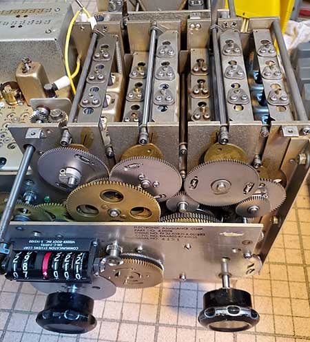
EAC RF Module - Nov 30, 2022 -  - The RF module had a severely bent upper support rod (right side) that had to be replaced using a duplicate rod salvaged from a "parts" RF module. The right side upper support rod at the back for the Vari-IF section was very oxidized so it was also replaced. The Veeder-Root counter was missing so the cam synchronization had to be determined. I rotated the MC to the right until I came to the stop. That being Band 31, I counted down as I rotated the MC to the left until I got to "7" at which point most of the cams lined up with their index markers. I rotated the KC shaft to the left to the stop and the rotated ten turns. I then carefully rotated slightly more until I hit the stop. The LF cams were very close to their index markers and with about half a turn of the KC shaft, all cams were aligned with their index markers. This should then indicate 07+000 on the Veeder-Root counter. I had a V-R counter salvaged off of a "parts" RF module that needed lubrication. After it "loosened up" a bit, it was set to 07+000 and mounted to the RF module front gearbox plate. The conical gears had to be adjusted for proper meshing for easy operation.

Next, I noticed that the Crystal Oscillator index wheel wasn't rotating as the MC was changed. The gear-to-shaft clamp was tight but the shaft slipped inside the clamped gear. I lubricated the shaft bearing and cleaned the two band switches. I used the slot at the rear of the switch shaft to rotate the shaft and felt binding with a grinding noise. I removed the entire Crystal Oscillator module (three screws) and then, when rotating the shaft, there wasn't any binding and operation was entirely smooth and light. The problem seemed to be the adapter bushing might be binding in the oil-lite bearing. Tried slightly changing the mounting position which helped a little. It feels like the mesh between the C-O shaft gear and the MC-drive gear was way too tight. There's no adjustment except to change the mounting position of the C-O module or to change the C-O shaft gear to see if that helps. I changed the shaft gear which slightly helped but still there was enough binding that the gear would slip on the shaft accompanied with grinding noises. I checked the gear plate to see if it was bent but it appears perfectly straight. It might be possible that the chassis of the C-O is slightly bent causing the misalignment - after all, the right side of the R-390A that this RF module was pulled from was hit with an ax. Replacement with another C-O should be revealing.


EAC RF Module and Gearbox came through the "ax attack" with only a few minor problems

Dec 1, 2022 - Indeed, changing the C-O (using a Teledyne module) eliminated the binding. I believe that the front panel of the EAC C-O module is very slightly bowed out and when the mounting screws were tightened it torqued the shaft and caused the binding. At any rate, the Teledyne C-O corrected the problem. I had to take the crystals from the EAC C-O and install them into the Teledyne C-O. Also, most of the Teledyne's band indication decal had flaked off so I had to mark the indication wheel accordingly (used a fine-point Sharpie.)

The slug rack for the 2-4mc RF transformers was missing. I salvaged one from the "parts" RF module. The 2-4mc ANT-RF transformer was also missing. I salvaged a Teledyne transformer from the "parts bag" of RF/Vari-IF transformers. Inside, the band switch looks to be in good shape. It has fiberglass switch wafers and the capacitors are either ceramic disks or polyfilm types, which is typical of the late-versions of the RF module. Further checking and the slug rack springs were missing on the 8-16mc rack. Installed spare springs from the parts. I guess the ax-wielder tweaked the right rear panel of the slug rack guide and that was jamming the .5-1mc rack. Using a long 1/4" thick piece of metal for a lever, I bent the slug rack panel guide slightly "more open" to get the proper clearance for the .5-1mc rack to slide freely.

RF Module Gearbox Flush & Brush - I've been doing all of this examination and rotating with the gears and bearings dry. Since nothing is binding, I don't think there are any real issues with the gearbox. I usually do a WD-40 "flush and brush" to thoroughly clean and work some lubrication into the bearings. The WD-40 is mainly used as a solvent so the bushings will have a drop or two of machine oil applied following the clean-up. The gears themselves shouldn't be greased. The slug rack roller bearings need to be cleaned and lubed. The slug rack channel guides shouldn't be lubricated. Same for the cam surfaces. If the cams were greased, then the rack roller bearings would just slide in the grease instead of rotating like they should.

Dec 2, 2022 - This EAC gearbox was pretty clean already. Didn't take too much WD-40 to have the gearbox looking and feeling like new. I usually leave an RF module out in the shop for a day to "dry out" from the "flush and brush" (sets on the concrete floor with a large rag under to absorb the WD-40.) Further clean-up and mechanical adjustments will be necessary before this RF module will be ready for electrical check-out. Usually, when building up a R-390A "from parts," the most time is spent on the RF module because it has the most mechanical operations that must be synchronized and work together smoothly and accurately. While the RF gearbox was draining, I continued on with the Main Frame.

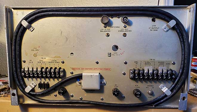
Main Frame Work - "Blue Striper" Main Frame - Examination - I decided to use the "Blue Striper" Main Frame because it has an almost perfect back panel. None of the terminal strip dividers are broken. It already has a nice condition power cable installed too. One of the side panels shows a considerable amount of wear to the iridite coating and some minor bends. The harness seems to be in good condition though very dirty, at least all of the Amphenol connectors are present. The bed plate shows some severe corrosion damage and the flex-finger grounding strip is entirely missing - maybe the corrosion is from its outdoor stay at St. Julian's Creek Annex. I plan on replacing the bed plate with the one from the "ax-attacked" EAC Main Frame. Having the Main Frame apart allows cleaning all of the mounting surfaces for best conductivity for good grounding. Also, proper hardware can be used in the reassembly.

While I'm exchanging bed plates, I also have to remove the old "Blue Striper" front panel, so all of the knobs and controls have to be dismounted. Missing from this front panel are both meters (but I have replacements) and the dial lamp bezel with the #328 lamp sockets (also have several replacements.) The AC power micro-switch was missing but I have replacements. Everything else seems to be present but very, very dirty. The entire Main Frame was filthy and had a lot of sooty-greasy-type deposits everywhere. As this Main Frame will be reassembled with the EAC bed plate, everything has to be cleaned. The Main Frame is an important component of the R-390A and provides many of the ground connections for all of the modules. With all areas clean, all modules will be grounded together through the Main Frame.

Dec 2, 2022 - Main Frame Stuff - The bed plate from the ax-attacked EAC cleaned up fine. It was missing the left side vertical divider on the underside. Luckily, I had a nice condition one that I had removed a few years ago while recreating the R-725. On the "Blue Striper" Main Frame, the right side panel was rough, so I robbed the right side panel off of the Imperial "parts set" that was still out in the shop. I had to perform a little body work to straighten some minor bends. The lowest screw hole to mount the rear panel wasn't counter-sunk but the left side panel I'm using did have this hole counter-sunk. I used a counter-sink bit to make this hole into a counter-sunk hole. Takes a 6-32 FH screw with conical washer when mounting the rear panel. In most R-390A receiver's this hole isn't counter-sunk (but I wanted the two side panels to match.)


Main Frame underneath with EAC bed plate installed


Main Frame topside with EAC bed plate installed

I dismounted the "Blue Striper" front panel. I noticed this must have been a Navy R-390A because a Diode Load pin jack was installed. Checking the harness and the additional wire running from the back panel to the front panel was present. Back when the meters were removed from many of the R-390As, usually the wires were cut right next to the meter terminals leaving nice long wires from the harness. Not this time. The meter wires were cut short with only about 1/2" lengths from the harness. That'll require wire extensions. There were sooty deposits on the top side of this Main Frame. Luckily, I'm only using the harness, the back panel and the left side panel. This rest of the sheet metal pieces are from other Main Frames. But, I had to clean the harness using isopropyl alcohol to remove the soot that had gotten into the wire bundle. Also, the same approach was used for cleaning the back panel terminals. Reassembled the sheet metal pieces to allow proper placement of the harness in the Main Frame.

Dec 4, 2022 - Function switch was missing the micro-switch. I replaced the entire Function switch. One wire broken off from the BFO switch terminal - repaired. AC to 3A fuse holder broken - repaired. Used DeOxit and a small paint brush to individually clean each rotary switch. Installed extensions for the Carrier Level meter wires that were cut short. Used correct coded wire from a junk harness. Attached using spiral TC junctions for splices that were soldered and then covered with shrink tubing.

Dec 5, 2022 - Finishing up the Main Frame - Installed the wire extensions for the Line Level meter using the same method of spiral TC junctions, solder and cover with shrink. Replaced the capacitor that mounts next to the CL meter with one from a junk harness. Had to redo some of the wires to the Local Gain pot (one was broken and the others were about to.) Detailed the wiring harness further to remove all of the greasy soot deposits. Checked the AC power cable and although it looked okay at a glance, the wire insulation inside was badly rotted. Replaced the AC power cable with a new one that was installed to have the hot and neutral wires inside the cover and only the cable and ground wire exiting. Nine of the terminal screws were missing and the four aluminum jumps necessary for normal operation were also gone. I harvested the screws and jumps from the "junker" Imperial out in the shop.

I found a really strange R-390A front panel in the upstairs storage with a really crummy paint job and weird silk-screening. But, it had excellent grab handles and a really nice shape dial cover. Both were removed and installed onto the EAC panel that is intended for this receiver. Next will be getting the Main Frame harness and controls correctly mounted to the rear of the front panel. Once the controls and harness are mounted then the fit of the panel will be checked to make sure everything goes together and no wires end up getting pinched. This is only a check fit,...the front panel has to be down for installation of the RF module.

Dec 6, 2022 - Front Panel Work - The front panel I'm using was on the '67 EAC receiver that ended up with a NSA Black Anodized panel, so this panel was excellent and was only removed from its receiver so I could install the black panel. This panel only required dusting to be ready to use. The grab handles were installed. I installed the two meters. These both had the mounting hardware but no lock washers. Instead green Lok-tite had been used sometime in the past. I'll add lock washers. The Dial Lock mechanism was installed and the Zero mechanism was also installed. When doing the final front panel installation, the Dial Lock has to be loosened and turned about a half-turn to clear the dial lock wheel on the RF module. I decided to install extensions on the two BFO wires that obviously had been pinched for years between the front panel and the Main Frame. One wire felt like it had broken inside the squashed insulation. I used spiral TC junctions and shrink tubing for the splices. The three 1/4" shaft panel bushings were installed finger-tight. All of the switches and pots were mounted into the front panel. I used internal tooth small trim lock washers on all of the control mountings with good condition nuts (finger-tight only at this time.) The harness had to be moved slightly every so often to get all of the controls to fit correctly. This is normal when replacing a front panel. Back to finishing up the RF module,...


Back Panel cleaned and completed except for an AC plug (clip for plug holder gone.) Also, the IF output BNC isn't installed (I do have a good J116 to install.)

Back to the RF Module - Dec 8, 2022 - Verified that the Teledyne 2-4mc ANT/RF transformer was going to be usable. Many times this particular RF transformer's primary coil will be burned due to 75M ham users not isolating the receiver during transmitting. Not using the Break In function and faulty antenna relays are normally the cause. Luckily, the Teledyne coil looked in excellent condition.

Cleaned up the residual WD-40 from the "brush and flush" operation. This gearbox was one of the cleanest I've done. And to think, it was almost destroyed by the "ax-attack" which did destroy most of the main frame.

The Veeder-Root counter that I installed was one that convenient to use. It wasn't in very good condition. So, I exchanged that Veeder-Root counter for one that was in excellent condition and rotated all of the number wheels easily. When installing the Veeder-Root counter, the mesh of the conical gears has to be adjusted by loosening the shaft clamps for both MC and KC, adjusting the position of the conical gear on each shaft for a good mesh (not too much though,) setting the proper numbers to show and then tightening the clamp. Too much mesh will result in some binding as the gears rotate. Just enough mesh for minimal backlash and easy rotation. 

Dec 9, 2022 - Removed all Vari-IF & RF slug racks. Removed all Vari-IF coils and all RF transformers. Cleaned the area of all sand and debris though there wasn't much. Lubricated all Oilite bushings with a drop of 3n1 oil (10w machine oil.) I found some of the roller bearings that are vertical guides for the slug racks were stuck and had to be oiled and rotated to get them turning freely. It's common for these small roller bearings on the vertical guides and on the slug racks to be stuck due to dirt and lack of proper lubrication. The vertical guides are bearings for straight side opposite the tapered edge on some of the slug racks. The roller bearings on each end of the slug racks rides on the cams. All roller bearings need to be checked for proper rotation and lubrication.

Variable IF section - Dec 10, 2022 - All receptacle sockets for the Vari-IF coils and RF transformers were cleaned with DeOxit applied with a small paint brush. I then use a small wooden toothpick to work the DeOxit into the socket. The wood doesn't scratch the gold plating and cleans the dirt and deposits out. Installed the Vari-IF coils. Each one had to be disassembled, cleaned and inspected before installation. Operation of the trimmer capacitor on each coil has to be tested to confirm that the rotor isn't stuck. The rotor contact for the trimmer and the plug-in pins are cleaned with De-Oxit. I replaced all three of the 18-27mc Vari-IF Z-213s because of excessive corrosion on the pins and internal deposits on the coils. Used Z-213s from the spare parts RF transformer bag. Had to replace one slug as it didn't seem to match the greenish-brown color that the Vari-IF slugs should be. Replacement was from a parts slug rack. On both Vari-IF slug racks, the individual slug holders needed to be adjusted so their travel up and down the coil barrel was mechanically aligned and without excessive rubbing on the inside of the barrel. Return springs installed and slug racks checked for proper operation using the MC and KC controls.

RF section - The same procedure is used here,...disassemble, clean and inspect each RF transformer before installing. De-Oxit used for the trimmer rotor contact and the plug-in pins. I installed the 16-32mc section first. The RF coils/transformers were installed as they were inspected and cleaned. Then the slug rack was cleaned and checked, then installed. Next, the 8-16mc section was installed in the same manner.

Dec 11, 2022 - Continued with the installation of the 4-8mc section in the same manner. The 2-4mc section was next. I found another 2-4mc ANT/RF transformer made by American Transformer Company in the upstairs storage area. It looks in very good condition with no apparent burns on the coil. I substituted this RF transformer for the Teledyne I was going to use. Then the 1-2mc section was installed followed by the .5-1mc section. The slug rack on the .5-1mc section was bent slightly and the guide roller bearing was misaligned. Straightened the slug rack frame to correct. All of the individual slug position adjustments were aligned for minimal rubbing of the slugs against the inside of the coil barrels. A couple of return springs needed a slight adjustment to the "hook" end so they would stay secured. The entire RF module was run from 00.000 to 31+000 to verify that all slug racks travelled without sticking or binding and that all of the roller bearings are rotating as they should. This completed the mechanical check-out and rebuild of this EAC RF module (with Teledyne Crystal Oscillator module.) The RF module needs to be installed and interconnected for the electronics check-out.

Receiver Assembly Begins - Dec 12, 2022 - The front panel details have to be completed before the RF module can be installed into the main frame. I installed lock washers on the two meters' screw and nut hardware, then the meter wires were soldered to the meters. The resistor board the mounts behind the data plate required two 6-32 FH undercut screws and proper ones were found in the spare hardware boxes. I saw that one of the switch contacts was bent on the 800~ Filter switch and it wasn't contacting the rotor contact. Using some small tools I bent the switch contact back into position. The front panel has to be near its mounting position in order to install the screws, washers and nuts for each of the three front panel mounted harness clamps. I used scrap wire twisted in the mounting holes to hold the panel in a position that allowed installing and tightening the harness clamps. I made sure the bushings were installed on the front panel and that the KC and MC shafts had the inside bushing installed.

Next, I placed the RF module into the Main Frame. I tested mechanical alignment by lightly tightening the captive screws - then loosen them a turn to allow some movement. Then I installed the three side mounting screws. These screws have Ny-loc type pem-nuts installed so a lock washer isn't required but because the clearance hole is oversize, I use a flat washer on the five of the seven RF module mounting screws. Also, these seven screws should have green painted screws heads to identify that they are part of the RF module mounting. I had to paint a set of screws for this installation. Five screws are .75" length and two are .5" length with the two shorter screws used in the front two screws positions. Once I had all the screws loosely threaded, I then tightened the four captive screws, then the three side screws, then the two left side screws (one screw also mounts a harness clamp) and finally tightened the two front screws. All screws that thread into Ny-loc pem-nuts only require a flat washer. The two in front screw into regular pem-nuts so a lock washer is required. I rotated the KC and MC to make sure nothing was binding.  >>>

>>>  Now that the RF module was mounted, I could proceed to install the front panel. I had already installed the harness clamps and installed the bushings so all that was necessary was to remove the "wire twists" holding the front panel in place and then lift the front panel into position to allow the ANT shaft and the KC and MC shafts to clear their panel holes and then the panel was gently pushed into its mounting position. I made sure the harness was within the clearance notch in the bed plate under the LINE LEVEL meter. Making sure none of the wires were going to be pinched, the front panel was secured using two of the front panel to Main Frame mounting screws. All of the control nuts were tightened. I made sure that the knob-stop was installed on the Function switch (prevents switching full CW-rotation to the blank position that was intended for the squelch modification.)

Once the front panel was secure, I turned the Main Frame/RF module on its side to allow access underneath. I then proceeded to tighten all five of the harness clamps. There are three on the front panel, one on the left side that uses one of the RF module mounting screws and one inside the PTO bay. There's also another harness clamp on the bracket that holds the antenna relays that needed to be tightened. The Dial Lock assembly was placed into position to allow it to clamp the locking wheel and then its mounting nut tightened. One more check to make sure everything had clearance and that there weren't any pinched wires.

This initial part of assembly that involves going over the Main Frame carefully and the detailed disassembly, inspection, cleaning and adjusting the RF module are the two most involved tasks that take the most time to complete. But, attention to detail at this initial stage will save a lot of time and work later on. So, with this most complicated work finished, the "receiver" is now ready for installation of the remaining modules.

Tubes - Dec 13, 2022 - The RF module and the IF module were both missing all of their respective vacuum tubes. I went through the "R-390A Spare Tube Box" and found a NOS 6DC6 for the RF amplifier. Most of the remaining tubes for the RF module were "used-test as new" spares that I had tested on a TV-7 tube tester. The exception were the three 6C4 oscillator tubes. One was a NOS spare but the other two were the "marginal" ones that end up being used just for initial testing. One 6C4 is just below minimum acceptable and the other one is about 10 above minimum acceptable. In some types of oscillator circuits, these marginal tubes would work fine but in the R-390A conversions, the oscillators have to test as "NOS" otherwise available RF Gain will be somewhat limited and the modulation of strong AM SW-BC stations will be limited. For testing, these marginal tubes are okay since I know what symptoms to expect. The IF module got all NOS 6BA6 tubes, "test as NOS" 5814s, a NOS 3TF7 and a NOS 6AK6. I had ordered two NOS 26Z5 tubes for the Power Supply module, so they were installed. The AF module had three of the four tubes installed - missing one 6AK6.

I made a "tube scavenging run" out to the shop's upstairs loft where all of the bulk spare tubes are located. I did manage to find one NOS 6C4 so I can eliminate the "below minimum" 6C4 which should help performance. Came back with a load of 6AK5, 6AK6, 5814A and 6BA6 tubes, most NOS or, at least, in a box.

IMPORTANT NOTE: Unfortunately, it's very common to find a tube that's in an original box and the tube inside matches the box and looks NOS. Then, when testing that tube, you find that it only measures minimum acceptable transconductance. I know that many, many "repair techs" wouldn't toss out the old "minimum" tube but instead put it into the box that the new replacement tube came in. I don't know why or what the reasoning was, probably "emergency use" or something like that, but they never seemed to have taken the time to mark the box or tube as "weak." I've run into these types of tubes many, many times. It's why I NEVER buy a NOS boxed tube unless that tube has also been tested. Lots of eBay "amateur tube dealers" don't test their boxed tubes and assume since the tube and box match it must be NOS but only by testing is the actual condition of the tube known ("known" to the parameters that the tube tester can determine anyway.)


photo left shows the Frankensteinesque R-390A fully assembled looking at the bottom. Amelco AF Module at the top of the photo. The sticker is from McClellan AFB in Sacramento, California. In the middle is the Cosmos PTO showing this photo was taken before I replaced the Cosmos with the Raytheon PTO. The lower module is the Amelco Power Supply. Note how the harness is routed when all of the harness clamps are installed along with the front panel fully mounted.

IF Module - Installed the IF module. I'd gone thorough this IF module some years ago and was using it in the Capehart R-390A, so it's in good physical shape and should function fine. It might even be aligned. I'm still "rounding up" nice looking tube shields so not all tubes have shields yet. The shafts and clamps for the BANDWIDTH and BFO controls have to be installed before the IF module is installed. Once the IF module is in place and the captive screws snugged-up (not excessively torqued*) then these two control shafts are installed onto the module shafts. The panel bushings have to be slightly loose to allow placing the shafts in alignment. Once in alignment then the clamps can be tightened. Then the bushings can be snugged-up. The coaxial cables were then installed and then the Amphenol connector plugged-in to complete the installation. I have to find a spare IF OUTPUT cable that connects from the IF module to the back panel IF OUTPUT connector. Should be one in the parts collection in the shop.

* SNUGGED-UP -  I use the term "snugged-up" to illustrate my frustration at always finding all of the screws, no matter where used, tightened to the point of requiring special tools to loosen. All of the screws in the R-390A use lock washers that only need to be tightened to the point where the lock washer is just fully compressed. Some screws thread into Ny-lock pem-nuts and these screws only need to be reasonably tightened. Set screws for knobs are routinely found over-tightened to the point where the set screw galls the shaft making knob removal difficult, if the set screw itself can even be loosened. This is such a common problem that all rebuilders must have an array of "over-tightened screw" removal tools in their collection of "special application tools." Fortunately, many of the rotating shafts in the R-390A use clamps rather than set screws.

Final Front Panel Work - Dec 14, 2022 - I cleaned the dial cover and, although it had been repainted sometime in the past, it was a nice example. I was test-fitting the dial cover when I noticed (or remembered) that I had only installed two screws to mount the Veeder-Root counter. Luckily, access to the V-R counter is very easy even with the front panel mounted. I installed the other two mounting screws and lock washers to complete the V-R mounting. To fit the dial cover required cleaning up the two solder terminals for the dial lamps wiring. Before soldering the two wires, I installed the two #328 lamps into their respective holders. Then the two wires were soldered to the terminals and the dial cover mounted to the front panel.

I also installed the five flat-head mounting screws on the lower left side of the front panel. Since these thread into standard pem-nuts a conical external-tooth lock washer has to be installed on each of these five screws. Also, the remaining six flat-head 8-32 screws that mount the front panel to the Main Frame were installed.

Another trip to the shop for "parts harvesting." Found all of the tube shields I'll need in an old junked Motorola police transceiver (nice ones.) I also ran across another boxed 6C4 that tested 70/55 on the TV-7 so it will replace the remaining "low" 6C4 that measured 59/55. Found an IF OUTPUT coax cable. Removed the Imperial data plate because it was the best original condition data plate that I have. Removed lots of hardware from the Imperial "parts set." Removed a set of knobs from the Imperial. Removed two sets of plug-in electrolytic capacitors. One set was in the Motorola "parts set" and the other set was installed in a spare AF module. Three caps passed their preliminary test but one failed miserably. If the three will reform, I should have a usable set for the AF module.

A Quick Reform - Dec 15, 2022 - For the best performance, the two multi-section filter capacitors should be replaced with the new plug-in multi-sections that are available from Nationwide Radio KE9PQ (about $125 for the pair.) Sometimes the original multi-sections can be reformed and will generally perform adequately. But, the original capacitor's life expectancy has already been exceeded, so they really are on "borrowed time" and replacement with new capacitors will certainly be necessary sometime in the possibly very near future. Reforming the originals is easily performed using a variable DC power supply and a DC current meter that can measure below 1mA (old style VOMs work fine.) Connect the power supply and the current meter in series. Use clip leads and be sure to observe the correct polarity of the connections to the capacitors during the reforming. Already have the PS turned on and set to some low voltage (<+10vdc is fine.) One at a time, connect each section capacitor to the PS/VOM. You'll see the current meter bounce upwards and drop down to zero. Ramp the DC voltage up and again the current will bounce. Continue to ramp up the voltage. The current should always drop down to some low value (the cap charging.) Go to at least >50vdc (100vdc is better) and leave the capacitor connected for about 10 minutes. The current should slowly drop well-below 100uA. If the capacitor current remains steady and doesn't pulse then the capacitor has started to reform. It will have higher voltage applied in the receiver but if it performs okay at 50-100vdc, it will probably do okay at 200vdc. The capacitors will continue to reform as they are used in the receiver circuit. This "quick reform" just gets them going in the right direction and "weeds-out" any defective capacitors. There will be five capacitors to reform. Three are 30mfd in one multi-section and two are 45mfd in the other multi-section. Once the capacitors have been reformed, discharge them and measure their value on a capacitance meter - just to verify they are going to function correctly. Typically, the capacitors will read slightly higher values than their marked capacitance and that's okay. Again, be sure to discharge the capacitors before measuring them, it saves your cap meter.

Cleaned the AF module, installed the tested tubes and installed the reformed multi-section capacitors. One note,...I was testing the 0A2 regulator tube not expecting anything other than the normal purple glow and the meter reading over 40. The 0A2 glowed bright purple and flashed repeatedly. The TV-7 meter was near full scale and fluctuating with the flashes. I hardly ever find bad 0A2 tubes but this one had all the indications of imminent failure. Replaced with a "tested-good" 0A2. Cleaned the PS module and installed the tested 26Z5 tubes. These two modules are ready to install. Only the PTO remains to be tested and calibrated before installation.

photo right shows the top side of the Frankensteinesque R-390A fully assembled,...well, the Utah plate and top cover aren't installed yet. Nearest is the Amelco IF module. In the middle is the Teledyne Crystal Oscillator and farthest is the EAC RF module.

The Underside - Dec 16, 2022 - I installed the AF module and the PS module in their bays in the underside of the Main Frame. I looked through the small spare parts bag to find a complete Oldham coupler for mechanically connecting the PTO shaft to the gearbox shaft. There are three pieces to the Oldham coupler consisting of two shaft-mounted "face" pieces and an inner coupler disk that is a metal piece with small channels cut in each side that are 90º opposed and mate with projections that are embossed in each "face" piece. Both "face" pieces are secured to the PTO shaft and the gearbox shaft with clamps.

PTO Testing - Since I have a test fixture for R-390A PTOs, it's very easy to check one out, do any adjustments that might be necessary and then, when satisfied with the performance, the "tested" PTO can be installed into the receiver. I selected four PTOs to test. The Raytheon rebuild, the Cosmos, a Collins and another unmarked PTO that was probably a Collins or Collins clone. The Raytheon had pretty good linearity with total error of about 4kc. The Collins was also fairly linear with a total error of about 4kc. The Cosmos had the best linearity staying within 2kc and a total error of about 2.5kc (actually it was a 5kc linearity error.) I didn't test the unmarked PTO. I installed the Cosmos PTO into the receiver (replaced with the Raytheon 12/28/22.) The PTO shaft will have a fiber bushing for the correct diameter for the Oldham coupler face piece. This has to be on the PTO shaft or the coupler face won't fit correctly. To ease installation, lightly grease one side only of the Oldham disc. That will keep it from falling off while the PTO is placed into position. Clearance is very tight and sometimes it helps to loosen the mounting screws for the rear PTO mounting bracket to allow a little more clearance while fitting the PTO into position. After the PTO captive screws are snugged-up then tighten the rear PTO mounting bracket. The coax from the PTO connects to the RF module routed through the hole in Main Frame bed plate. The power cable for the PTO comes from the PTO bay harness with an obvious connection.   >>>

>>>   Quickie Test - With the PTO installation, the R-390A was at a point where power could be applied. Of course, I did have to install an AC plug first. I connected a 600Z loudspeaker to the LOCAL AUDIO terminals on the rear and used a C-bnc adapter for the antenna input connecting a ten foot wire for the antenna. I used a Variac at first and brought the receiver up to 115vac input. No dial lamps,...well, very dim dial lamps. I didn't check the lamps when I installed them and they were more of those #345 lamps. Replaced the #345s with #328 lamps for proper illumination. There was some life in the receiver, background noise, BFO operational but no signals and no CAL signal. Set the dial to 00780 for KOH, the local AM station. Once the MC dial was rocked, everything came up a little louder and KOH was weakly being received. But, if the MC dial was put on the detent, the KOH signal dropped out. Considering the the PTO hasn't been synchronized to the dial readout, the Vari-IF and RF coils have all been removed, inspected (trimmer moved to confirm that the rotor wasn't stuck,) some replaced and then reinstalled and then all of the slugs haven't been adjusted and some of the slugs and slug racks are from different RF modules. Also, all of the crystals in the Crystal Oscillator came from a different module. It's actually surprising that much of anything was actually received using a ten foot wire for the antenna. Definitely, further mechanical adjustments are going to be necessary along with a full IF/RF alignment.
Minor Mechanical Problems - Dec 17, 2022 - For the following tests I used the HP606B to inject a 455kc signal into J118, the IF input. This checks just the operation of the IF module, the AF module and the PS module. The audio output was way down but slightly moving J120 on the AF module would make the audio disappear. I took the Amphenol connector apart and found the junction for all of the shields had a broken wire to ground. Also one receptacle socket was very loose. The socket was tightened using a very small blade screwdriver as a wedge to close the socket opening to tighten its fit to the mating pin. Also, cleaned J120 with DeOxit. These repairs fixed the audio cut-out when J120 was moved.

The audio really got loud if the unused Diode Load terminal wire was physically moved a bit. It seemed to be in the harness. The Diode Load wire entered the harness next to one of the panel harness clamps. It appeared that the clamp was pinching the wire bundle due to the additional Diode Load wire that was actually a shielded cable. I took off the harness clamp and cut the Diode Load cable back to the next fabric harness cover. I then cleaned the wire bundle where the pinching seemed to be happening. Then wrapped the wire bundle with several layers of friction tape to make some padding. I then reinstalled the cable clamp. After completion, the audio output remained at a high level and didn't change if the harness was moved. It's unfortunate that this "Blue Striper" harness was the only complete harness that I had. All of my other harnesses have been "chopped" by scrapers or destruction technicians.

In checking visually only (not a good thing to do) I cut a wire that was on the rear terminal for the LOCAL OUTPUT assuming it was a mod. After checking the schematic, I found out I had cut the return wire from the PHONE jack (connects the phones through a resistor to ground.) Used a spiral TC junction to solder splice the wire back together.

Vari-IF and RF Alignment - Dec 18, 2022 - I had already aligned the IF module some time ago. It maybe could use a "touch up" but I wanted to get the receiver thoroughly working first. I'd already ran a 455kc signal through the back-half of the receiver and performance was as expected. Only the front end seemed to need some help. Since this receiver was built-up from various parts and modules, it's to be expected that many of the adjustments are going to be pretty far out (and they were.) I had to use fairly strong signals at first because someone sometime in the past had screwed the L adjustment of the Variable IF transformer T403 all the way down (talk about attenuation.) Once that was corrected, then the Variable IF aligned normally. The Crystal Oscillator trimmers all were fairly close and that's normal for this module - even when the crystals have been changed. The RF section had some coils that were pretty far out and others that were very close. Since many parts were used to build-up this part of the RF module, it's expected. As all of the various adjustments were made the signal generator level had to continually be reduced. The signal generator level should be kept at a level that produces about -7.0vdc on the Diode Load terminal. I did this preliminary "troubleshooting-testing" alignment with the receiver Bandwidth at 4kc. 

Completed RF alignment with no issues. I connected the 135' tuned Inv-Vee set for 20M and tuned in a VK5 from western Australia on 14.195mc who was very strong and had quite a "pile-up" going on. Heard all of the stations calling with most being from USA midwest. WWV on 15mc was 4kc low but I haven't cal'd the dial, very strong. This was just a "quick alignment" to find any problems. The receiver works pretty well but I can tell it's had a lot of wear in the switches on the front panel with that being the fault of the harness from the "Blue Striper." But, considering it's a history at St. Julian's Creek Annex, I guess I'm lucky it even works.

Dec 19, 2022 - Continued "test listening" and received all of the Chinese Coastal Beacons in the 16mc range and the South Korean Coastal Beacons on 12mc. Tuned in several SW-BC stations in the 15mc band and also the 11.7mc to 12mc band. Listened to a few hams on 20M but, being Monday, no exciting DX. A couple of minor issues noted. The tuning seems fairly stiff and when tuning CW or heterodynes, the tuned frequency seems to change in "steps" like something in the gearbox is not smoothly rotating. Further investigation required, it's minor and isn't noticed on SSB or AM signals. I probably have to further synchronize the PTO to the dial as I have a 4kc error that is persistent on all bands. I had to reduce the IF GAIN adjustment to about 66% and still had lots of gain but at this lower setting the background noise is greatly reduced. Most SW-BC stations still push the CL meter to about 50, which is fine.

Dec 21, 2022 - For the most part, the "Parts Set R-390A" is done. There's still some fine tuning and little mechanical tasks to be finished. I'll certainly do a black lacquer "touch up" on the knobs and leave just a little of the wear showing. Any interesting developments will be added below as "UPDATES."

Boneyard Parts Sources Used - This R-390A ended up with a Main Frame that was built-up using some of the "Blue Striper" parts (the harness and the back panel plus the left side,) the bed plate from the "ax-attacked" '67 EAC and the right side panel from the '63 Imperial. The front panel is from a different '67 EAC. The RF module is from the "ax-attacked" '67 EAC. About half of the RF transformers and coils are American Transformer Co. with the other half being EAC units. The Crystal Oscillator is a '62 Teledyne parts module but the crystals came from the "ax'd" '67 EAC C-O. The IF module is a '62 Amelco pre-aligned and used module that had been in a '61 Capehart. The AF module is a '62 Amelco parts module but the multi-section filters were from a parts Motorola AF module. The Power Supply module is a '62 Amelco parts module. The PTO is a Cosmos of some vintage from the spare PTO collection (replaced with a Raytheon rebuilt PTO on Dec 28, 2022.) The knobs were mostly from the Imperial "parts set" but a few were harvested out of the spare knob "parts bag." The receiver is mostly Teledyne-Amelco-Imperial parts and modules along with some EAC parts and an EAC RF module. It seemed appropriate to install the '63 Imperial Electronics Inc. tag from the Imperial "parts set."


Imperial Electronics, Inc. R-390A - "Frankensteinesque" aka "Made from Derelict Boneyard Parts"
 

UPDATE: Dec 22, 2022 - The "stiff" tuning and "stepped" frequency increments while tuning has completely disappeared. I've been using the receiver everyday to get it some "run time" and always operate it on many different bands so the gearbox and the RF module slug racks all get time to "work in." Smooth frequency tuning now, even on CW. Sometimes very slight mechanical misalignments will improve with use. Also, lubricants sometimes need time and movement to distribute themselves into the bearings for smooth operation. At any rate, the tuning is smooth and feeling light now.

Received Trenton Military today on 15.035mc USB with air weather out of Trenton, Ontario. Signal was about 5 by 6. Also, heard a ZS6 working several state-side stations on 20M. His signal was easily 5 by 7. It's normal for a receiver to improve in performance somewhat with use after a reworking like this one has had. All of the modules have been setting around for years without power and probably were thrown around during any moving that happened. Same with the NOS and "test good" tubes - they've been setting around for years with no power on them, just setting in a box,...aging. As all of the components and mechanics get back to actually "working," things tend to improve over the next few days to a week or so. Since, the receiver seems to be performing quite well I'm going to pull the PTO out and do the EPE adjustment. This PTO had about a 2kc EPE which isn't terrible but the linearity was off some in the middle of the range. Usually, if the EPE is set to minimal error then the linearity is also improved.

On reconditioning the knobs,...I've been experimenting with using black paint pens for touch-up and they do work quite well. Also, anyone that has tried using a "black" Sharpie has certainly noticed that these markers are actually dark purple and the purple really shows when trying to cover bare metal. I've had pretty good results using "pen+GEAR Permanent Marker" because their black ink is really black and covers bare metal much better than a Sharpie. Best results with "pen+GEAR" will be to apply to the area to be touched-up and then gently wipe lightly with a clean flannel cloth. This will dull-down the ink and blend it with the original paint. The same can be done when using the black paint pens. Apply and gently wipe lightly to dull-down and blend the touch-up. I've been using a combination of both paint pen and the marker. Paint pen for missing paint and chips, then the marker for scuffs and discoloration. The combination works quite well. Of course, perfectionists can strip, prime and repaint then fill the index line for perfect knobs but in the real world repair depots "touch-up" of the knobs was the norm.

UPDATE: Dec 27, 2022 - I pulled the Cosmos PTO to try to improve the EPE. Testing the Cosmos PTO on the fixture I found that the EPE was about 2kc but there was a linearity error about mid-range that was 5kc. I removed the L701 trimmer access hole cover screw. The trimmer was severely gnarled and not moveable. I tried several different tools but apparently someone either put Lok-tite or glue down the adjustment threads. It was obvious that someone before me had attempted the EPE adjustment and they had gnarled the trimmer trying to get it to move. It just isn't going to move. So,...on to another PTO,...the Raytheon-rebuilt PTO worked pretty well when I had tested it earlier. The EPE wasn't too bad at about 4kc. The access cover screw was missing but looking down the barrel I could see the trimmer was in good shape. I also tested that the trimmer was indeed moveable. The Raytheon was put on the PTO fixture and with a few adjustments and tests a good setting for L701 was found. EPE was about 1kc and the linearity tracking error never exceeded 1kc. This Raytheon PTO was in the "Blue Striper" and it does appear to have been out in the elements. But, because the PTO is located on the underside of the Main Frame it's protected to a certain extent. Although its cover is slightly pitted, it's really not bad and internally it tracks very well now. The metalized Raytheon label is very cool. So, I'll install and synchronize the Raytheon PTO tomorrow. Photo to the right shows the ultra-cool metalized label on the Raytheon PTO (it's installed in the receiver in the photo.)

Dec 28, 2022 - Installed the Raytheon PTO. Very carefully set up the synchronization of xx+000 on the Veeder-Root counter to equal 2.4550mc on the PTO output. I had verified that the mechanical ZERO was set at mid-range. The DIAL LOCK had slipped the C-clip out of the groove and up the shaft. That didn't allow the clamp to tighten on the lock wheel. Re-installed the C-clip to correct. Powered up the receiver with it set to 10.000mc and WWV came right on as the receiver warmed-up. I "zero'd" using 2kc bandwidth and the ZERO control. With 10.000mc tuned exactly, I switched up to 15.000mc and WWV was still tuned, as expected. I shouldn't see more than a 1kc error when tuning from the low end to the high end on any band. The tuning accuracy is all in how well the PTO is set up and how accurate the crystals are in the Crystal Oscillator.


Raytheon-rebuilt PTO


1967 Electronic Assistance Corporation R-390A SN: 974 - Restoration Log (2016)

This was my first "journal-type" of write-up from about seven years ago now. That's why the explanation that follows,...

The following write-ups are little different from my usual restoration write-ups. I've written this one in the form of a journal or log that has daily input as the project progresses. I hope this approach gives the reader an idea of the order in which the restoration-rework takes place and the problems encountered along the way as the work progresses. It will also show the reader about how long it takes to complete an R-390A that isn't in terrible condition but certainly was non-operational and incomplete.  - H. Rogers, Aug 2016.

July 16, 2016 - Ham & Hi-Fi, a vintage audio, vacuum tube and ham radio business in Sparks, Nevada, had its semi-annual Open House Sale today. Lots of bargains and "freebies." I was interested in a decent-looking R-390A that was priced at $70. Not complete by any stretch but I was pretty sure I had all of the missing parts. I asked owner Ethan, "Is this R-390A seventy dollars?," just to verify. "Yep!" Hmmm. I paid Ethan and went looking for a hand truck to move the receiver out to the car. When I returned, my old friend Mike W7MS, was giving the R-390A a real "going over." "Well, I see the 3TF7 is still there. That's a surprise. It's missing a slug rack and RF coil though. I bet it's missing all of the crystals, too." Mike had flipped the R-390A over when I broke-in, "I already bought it, Mike." To which we both had a good laugh at the fact that Mike was critiquing my receiver purchase before I could even get it off the table.
 

July 17, 2016 - Once I got the R-390 home I was able to inspect it more thoroughly. Mike was right,...all of the crystals had been taken out of their sockets. There should have been 17 crystals and all were missing. The cover had been screwed down so tightly, I thought that nobody had been in there,...ever. Also missing was the 4-8mc RF-Ant transformer, the 4-8mc slug rack and slugs, all of the tubes in the RF deck, top and bottom covers, the Utah plate, the front panel bushing for the KC tuning. Both meters were non-original types that were similar types but not correct. On the good side,...the dial had a security flip-down dial display cover, the 3TF7 was good, both 26Z5 tubes were present (and tested good,) the receiver was a 1967 EAC contact with the correct data plate and all of the modules were correct EAC with the correct contract number on each module. None of the sheet metal was "bashed" and, mechanically, everything looked okay. Luckily, I had a couple of "parts sets" and extra modules so the missing parts weren't going to be too much of a problem. The receiver was extremely dirty with loads of greasy, oily contamination that had very fine black powder mixed in. The receiver had obviously been stored in a garage or machine shop or some other location where oil and fine black powder would be everywhere.
 

July 20, 2016 - Started complete tear-down. All modules out, front panel off, all parts plastic bagged and tagged.

photo above: The 1967 Electronic Assistance Corp. R-390A Order No. FR-36-039-N-6-00189(E) - SN:974 after the rebuild. Though these late-version receivers look exactly the same on the exterior, inside are where several changes were incorporated as the receiver design evolved. Most changes involve the types of capacitors used with these late-versions which use many ceramic disk and metal film capacitors instead of the paper dielectric types used in the earlier receivers. The PTO will be built by Cosmos Industries. A different crystal oven-crystal cover is used on these later receivers. The security dial cover is found on some receivers and is shown in the "raised" position.
July 21-23, 2016 - Cleaned front panel. I was amazed. I thought the front panel was kind of rough but it was all just the oily dirt and black powder getting into the engraved nomenclature. Careful cleaning first with WD-40 and a soft brush followed by Glass Plus to remove the WD-40 residue resulted in the front panel looking first-rate.

Complete disassembly of the Main Frame was necessary because the oily dirt had worked into the side panel joints due to loose screws. Again, under the dirt everything was in excellent condition.

July 24 - 28, 2016 - Took RF deck outside for a WD-40 flush of the gear box. The Veeder-Root counter was very dirty and I thought the digits were damaged but, again, it was just the black dirt causing the problem. Luckily, it comes off easy with WD-40. Stripped down the RF deck by removing all 24 RF and VIF transformers, slug racks, return springs. With no load, the KC tuning was checked for "feel" which was normal. Same for MC tuning. Checked cam synchronization by setting tuning to 07+000 and found that the 4-8mc cam was way off. Probably why the 4-8mc RF coil was missing - a former owner was chasing a problem in the wrong area of the receiver (also noted that the mica capacitors had been replaced in remaining two 4-8mc RF transformers.) Mechanically reset the 4-8mc cam to correct position. Replaced the missing 4-8mc transformer and also replaced the remaining two that had been "worked on." All other cams were in alignment. Cleaned and inspected ALL 24 RF & VIF transformers checking for proper rotation of trimmer on each. The replacement 4-8mc RF coil needed to have the trimmers "unstuck" and repaired before it could be used. Cleaned all slugs of dust and any other dirt. Cleaned all slug racks and lubed cam rollers. Reassembled the RF deck, adjusted the fit of all slugs into their respective coil barrels and then checked operation of all of the cams, slug racks, slugs and cam rollers.
July 29 - 31, 2016 - Installed a set of crystals in the RF module-Crystal Oscillator (17 crystals required.) Cleaned rotary switches. Reinstalled the RF module back into the Main Frame. Cleaned and lubed all controls and switches for front panel. Remounted harness and all controls to the front panel. Installed two #328 bulbs in the dial cover (originals gone.) Mounted front panel to the Main Frame temporarily - checking for fit. I only installed four screws since this panel will have to be "dropped down" for PTO end-point adjustment and probably for other things, it's best to just mount it in this manner for now. Original knobs were rough. Since I had a full set of restored knobs, these restored knobs were mounted to the control shafts.

August 1, 2016 - Tested the two can electrolytic capacitors and found the triple-30uf to have one defective section. The dual-45uf seemed to reform okay but the values are not very close. Same with the two good sections on the triple-30uf. I will have to rebuild these two units using new electrolytic capacitors for best reliability and performance. I had several spare R-390A can electrolytics and when testing them I found that ALL were defective in some way. Probably time to admit that you can't use and reuse the original, fifty-year-old caps anymore. New electrolytics ordered and on the way.

August 2 - 6, 2016 - While waiting for the replacement electrolytic capacitors, I tested all of the tubes and cleaned the tube sockets on the IF module and re-installed it into the Main Frame. I also had to locate tubes for the RF module since all were missing. The other modules all had W.P.M. heat-reducing tube shields so I also needed to find tube shields for the RF module tubes. All I had was IERC-type, which are very good heat-reducing tube shields, but they don't look like the W.P.M.-types. Since most of the tubes in the RF module are covered by the Utah plate, I went ahead and used the IERC-types.

August 7, 2016 - I can't find a 6DC6 (RF Amplifier) anywhere in the R390A spare parts or in any of the tube boxes. I will have to order a couple. They aren't expensive tubes but I never seem to have any NOS ones around for some reason.

August 8 - 11, 2016 - Rebuilt the two multi-section electrolytic capacitors. Photographed for the added write-up on this procedure that is now in this web-article in the Audio Module section. Picked up four NOS 6DC6 tubes from Ham & Hi Fi. Installed the remaining modules into the main frame.

Since I didn't set the Veeder-Root counter to XX.000 before removing the RF module, the PTO was not pre-set to 3.445mc. This is a minor inconvenience that requires the PTO be set by powering up the R-390A and measuring the frequency out of the PTO with a digital frequency counter. The procedure I use is above in the PTO section of this web-article.

Since I had already powered up the R-390A, I went ahead and hooked up a 600Z ohm speaker. I had lots of noise but the calibrator seemed pretty weak on 40M. I connected an antenna and tuned around 40M and heard a few SSB stations. Now this R-390A has been completely apart and is certainly quite a bit out of alignment but still it picked up a few signals. This should be a very good sign of things to come.

August 12-14, 2016 - I've been checking out performance of the R-390A before alignment by listening to various signals on different bands. This gives everything a chance to operate at voltage for awhile to make sure everything is going to function. Since the only "repair/changes" occurred in the 4-8mc RF section with the installation of different RF transformers along with different slugs and slug rack, it was kind of a surprise that the 4mc, 5mc, 6mc and 7mc bands actually would tune in the Calibration oscillator. I was really pleased with the performance on the bands 8mc and up. I had manipulated all of the trimmers on all of the RF and VIF transformers to verify that the trimmers weren't stuck, so I was surprised that 20M and 19M SW performed quite well. I checked for the Calibration oscillator signal on all bands and it was present. I tested the end-point error on the PTO and found it to be 8.0kc. That's the greatest EPE that I've ever encountered, so we'll have to see if the compensation adjustment can correct that much error. I dropped the front panel since that was going to be necessary for the EPE adjustment. I installed all of the correct hardware to mount the correct type meters and soldered the connecting wires up for both meters. After the EPE adjustment I will be able to fully mount the front panel with all screws and washers and proceed with the full IF, VIF and RF alignment. August 15-17, 2016 - See PTO section on Cosmos PTO. I added my experience with this Cosmos to that section of this article. The EPE adjustment is virtually inaccessible from the front through the locking plate and the front and rear gearbox panels. I had to remove the PTO each time to make the adjustment and then reinstall to test. Very time consuming. I was able to adjust the EPE from 8kc down to 0.5kc. Remounted the front panel with all screws, locking washers, shaft bushings, etc. Checked output on the Crystal Oscillator section and adjusted all trimmers for peak output.

August 18-20, 2016 - Peaked the mechanical filter inputs and outputs. This requires having the IF module dismounted but still connected to power. Photo and method described in "IF Module" section further above in this article. All mechanical filters were pretty close so, just minor tweaking.

August 21, 2016 -  Completed the full alignment. Most adjustments were pretty close but, as expected, the 4-8mc section was quite a bit out of alignment. Installed the Utah plate, top and bottom covers. Connected receiver to the full-size ham antenna. 40M reception is normal now. All other bands are functioning correctly. Adjusted Carrier Level Meter and IF Gain for best performance.

1967 EAC Performance and Observations - Here's what I've noticed on this receiver that is somewhat different than the earlier versions, such as the Collins or Motorola R-390As.

1. Components - many ceramic disk capacitors in RF and IF modules. These modules also have several capacitors that appear to be metalized film capacitors. The AF module appears to have similar capacitors to the old Vitamin-Q types but I think the construction is different with better seals. Certainly the multi-section filter capacitors are of the same construction and questionable reliability. They have the same problems that are found in any multi-section electrolytic capacitors that are half-a-century old. Overall, the most of the capacitors seem to be better types than those used in the R-390As built in the 1950s. Cosmos PTO is difficult to adjust the EPE due to the new location of the L701 adjustment behind Z702.

2. Performance - is definitely equal to a rebuilt and recapped earlier version receiver. IF Gain is set at about 60% which is pretty close to where it's adjusted on the recapped earlier versions. With IF Gain set at 60%, most SSB signals demodulate nicely with the RF Gain at about 5 to 7 and the AF Gain at 7. This is using a 135 ft center-fed tuned inverted-vee antenna. SW BC stations usually run about 50 to 60db on the Carrier Level meter depending on the station and the time of day. The coupling capacitors in the AF module were NOT changed to .02uf but the audio sounds very good with noticeable bass response on AM BC and SW BC. Also, strong SSB stations and AM ham signals seem to have good bass response with the original .01uf coupling caps. Overall, a nice performing R-390A that is going to be set up with one of my ART-13A transmitters for awhile.

Time to Complete Project - It took just about one month to complete the rework on the 1967 EAC. This is from a non-operational, incomplete receiver to an entirely functional and totally complete receiver. I didn't work on the receiver everyday so total time actually spent on the project was probably around 20 hours.

Update - Sept. 4, 2016 - I guess I should have cleaned the Antenna Input relay contacts. The procedure is described in the Main Frame section further up this page. It's not difficult to do, even if the receiver is already back together. The symptoms were no (or very little) carrier level indication, a change in the normal position of the ANT TRIM for resonance and relatively weak signals. If STAND BY or BREAK IN were actuated then the signals would return to normal levels. This was the typical indication that the antenna relay contacts were introducing some resistance due to poor contact. In this particular case I don't believe the cause was oxidation because inside the arm, NC and NO were very clean looking. I used just a slight bit of DeOxit and paper to clean the contacts to have them measure zero ohms. Problem might have been some kind of rosin-like coating or something that dissolved with DeOxit. Other than this minor and easy to correct problem, the '67 EAC R-390A has been performing very well.

Update - March 7, 2018 - Read "Creating an Authentic Arvin R-725/URR" in Part 3 to see what's happened to this '67 EAC R-390A. Here's a quick link R-390A Part 3


Not Another 1967 EAC Restoration Log?  (2017)

May 24, 2017 - I saw this R-390A at yet another "Open House" at Ham and Hi Fi in Sparks, Nevada last year. It was $100 "as-is." The yellow power cord and the 600Z matching transformer mounted on the back panel must have scared off any potential buyers, including me. I was tempted though, since the receiver had both original meters. I "stewed about" this R-390A for awhile and would usually go into the back storage area at Ham and Hi Fi just to see if it was still there. Finally, about six months had gone by and I was again looking at the R-390A that had a 1963 Imperial Electronics tag on the front panel. I asked Ethan if it was still for sale since it had been stuck way in the very back of the building for months. "Sure, I was asking $100 for it at the last open house. Is that okay?" I replied, "Yeah, the parts on the front panel are worth that to me." So, into the truck went this newest R-390A.

When I got the R-390A home, I had to investigate that yellow power cable and 600Z ohm transformer. The yellow cable certainly wasn't original but its installation didn't do any damage either. Same with the 600Z transformer that was utilizing an existing stud for mounting. While looking at the back panel I noticed "Electronic Assistance Corporation" with the "FR-36-039-N-6-00189(E)" order number and the "DAAB05-67-C0115" contract number stamped on the back. I then looked at the Crystal Oscillator (attached to the RF deck) and saw the same stamping. I noted that the electrolytics on the Audio Module were date-coded "67." So, I pulled out all of the modules except the RF deck and to my surprise they were all 1967 EAC modules on the FR-36-039-N-6-00189(E) order and DAAB05-67-C0115 contract from 1967. This receiver was a 1967 EAC R-390A that for some reason had an Imperial Electronics tag installed. Further inspection revealed that the receiver was nearly complete and original. The only missing parts were the correct ID tag and the "Utah plate."

Although I had originally thought when purchasing this R-390A to use it as a parts source for my 1961 Capehart (with OD front panel) this one is just too nice and original for that purpose (the Capehart will just have to wait.) I'll get started on this '67 EAC during the summer and write a restoration log as I proceed along with the rebuild.

June 12, 2017 - Started on this EAC. I had already obtained an original Utah plate and a repro '67 EAC data tag. All the modules except the RF module had been pulled and were setting with the receiver. I started with the IF module, the AF module and the Power Supply. Each module was cleaned and the tubes tested. Any weak tubes found were replaced. The two electrolytic filter capacitors were reformed. These capacitors were date coded 1967 and both checked okay. Reforming seemed normal with the two 40uf caps drawing about 10uA after reforming at 280vdc and the three 30uf caps drawing about 15uA to 25uA at 280vdc after reforming. The final test will be to see how the filter caps perform in the receiver. I didn't have very good luck with the last EAC receiver's filter caps which had to be rebuilt. These filter caps seemed to form nicely but performance is the final test.

June 13, 2017 - Completed cleaning and tube testing on the above modules. I had to double-check the wiring on this EAC power supply as the wiring didn't look like most PS modules. Though the wires were not "tucked" under the chassis, as is normally done, the wiring was correct. Just an anomaly of that particular PS assembler and final inspector. I had to replace all of the 5749 tubes in the IF module since they all tested weak. They were all RCA-JAN brand and date coded 1965. Also, one 5814A in the IF deck needed to be replaced. On the AF module I replaced one 5814A. Both 26Z5 tubes checked okay in the PS module.
 

June 14, 2017 - Tested the tubes in the RF module. All were weak except two 6C4 tubes and one 5814A tube. Checked cam synchronization at 07+000 and found all cams to be close. Looking at the photo of the receiver to the right one can see the UEW Union sticker applied to the front panel below the Carrier Level meter. I tried Glass Plus and Goof Off with no effect. WD-40 however was able to loosen the glue and the sticker came off without leaving any residue. Why someone would apply any kind of sticker to a high-level communication receiver panel is unknown and seems like something that an 11 year old would do (not to malign 11 year olds, but they do seem immature, don't they?) Luckily, it came off with no issues. Cleaned the front panel with Glass Plus. This was just a quick cleaning to see what the overall condition was and it was excellent. The knobs were also in excellent condition. The Main Frame sheet metal was also in excellent condition with no corrosion. I put the Main Frame with RF deck and PTO installed on the bench for further "tear-down." Photo to the right shows the receiver before tear-down. Note the UEW sticker adjacent to the Function switch.

June 19, 2017 - Pulled PTO, no backlash spring on coupler. Pulled RF deck. Cleaned Main Frame bay. Disassembled RF deck for WD-40 gear wash. Roller came off of slug rack on the 18mc-32mc rack. Retaining washer missing. Will have to assemble another 18mc-32mc rack with the slugs from this receiver.

June 21. 2017 - Did the WD-40 flush on the gear box. There was some kind of grease coating on the cam surfaces that had dried hard (probably Lubriplate.) Had to scrub with acid brush and WD-40 to remove. No other problems. Gear box has very light "feel" now. Was pretty "stiff" to begin with. After cleaning up the WD-40 residue, removed all RF and variable IF transformers for inspection and cleaning of bed plate and contact pins-sockets.

June 22 - 25, 2017 - Cleaned and inspected all 24 RF-Variable IF transformers. Checked trimmers for proper operation. Cleaned pins with DeOxit. Re-installed all transformers. 18mc-32mc slug rack roller bearing was defective. Replaced slug rack but installed the original slugs (they were the late-versions with "Collins" on them.) Cleaned and lubed slug racks and bearings. Adjusted all slug mounts for best alignment with the slug barrel of each RF-Variable IF transformer. Checked mechanical operation. Aligned two slug rack lifter cams for better alignment at 7.+000. Holder for dual crystal assembly was missing. Installed holder robbed from "parts chassis." Checked switch alignment for Crystal Oscillator. RF module is ready to re-install into Main Frame (except for tubes.)
June 26 - July 1, 2017 - Installed new AC power cable with military metal AC plug in Main Frame. Cleaned inside and rear panel of Main Frame. Installed RF module into Main Frame. Cleaned the backside of the front panel. Remounted front panel and secured harness clamps. Cleaned all knobs. Installed IF module, PS module and AF module. Cleaned PTO. Checked the 5749 PTO tube - it was bad so installed NOS 5749 tube. Installed PTO into Main Frame. Since I had removed the PTO with the Veeder-Root counter at 07+000 (and I hadn't changed the position of the PTO shaft) I set the counter to 07+000 and then while installing the PTO I also installed the oldham coupler disk. The PTO was difficult to install so I loosened the rear PTO mount at the two screws that secure the mount to the Main Frame. After the PTO was in position, I then tightened the screws securing the rear mount. Connected all cables and power plugs to all modules. Powered up the R-390A and, with the Calibrator and BFO turned on, tuned in 07.500mc to receive a "marker" signal. I then rotated the MC dial through its entire range from 00.500 to 31.500mc and heard the "marker" signal on all bands. This indicates that basically the R-390A is working on all bands but the receiver still needs to be aligned (since it was totally disassembled during the inspection, cleaning and testing process.) Connected a 20' wire on the floor as an antenna and tuned in WWV on 15mc and on 10mc. Also, a couple of SW-BC stations around 12mc. Although the R-390A did receive these signals, it was obvious that a complete alignment would be necessary (and expected.)
July 2, 2017 - Test that the mechanical ten turn tuning had proper over-range - +38kc and -30kc, which is okay. Tested end-point error. Odd in that linearity seemed poor. 0 to 200 was about 4kc, 200 to 800 was about 1kc, 800 to 1000 was about 3kc. If measured from 0 to 1000 the EPE was about 7kc but between 200 and 800 the EPE was only 1kc. Tested the actual frequency output of the PTO to see if the mechanical xx.000 to xx+000 is 3.455mc to 2.455mc. This shows if the PTO is actually synchronized with the Veeder-Root counter. I did a mechanical relationship in that I didn't change the PTO shaft after removal and installed it in the same position at xx+000 but that doesn't check that it was correct to begin with. The only true test is to measure the PTO frequency at xx.000 and xx+000. The PTO should be synchronized to using a digital frequency counter. The non-linearity also then can be seen by measuring the output frequency at 100kc intervals.

July 3, 2017 - I decided to swap PTOs with my other '67 EAC. When I get time, I'll correct the EPE on that PTO (or test it.) Meanwhile, the PTO I've installed has about 500 hz EPE and is linear across the 1.0mc span.

UPDATE - Sept.24,2017 - Checked out the non-linear PTO. With xx.000 = 3.455mc at +xx.000 = 2.458mc or about 3kc of EPE. However, if the frequency is tracked every 10kc the excursion out of linearity is as much as 8kc off. It appears that the PTO may have been checked at the end points which was 3kc off and not checked for linearity. Maybe this is one of the "rejects" that were sold directly to civilians. At any rate, this PTO could be disassembled and perhaps the linearity adjusted for better performance. This is accomplished by adjusting three screws on the rear threaded mount of the ferrite core. This "pushes" the position of the sliding linearity arm that rides on an aluminum rail which hopefully compensates for non-linearity by slightly moving the core over a fairly long span. I'm not really sure anything would be gained by going into the PTO. The actual non-linearity of this PTO can be compensated for by adjusting the CAL to the closest frequency and the resulting accuracy is about 1kc over a couple hundred kilocycles. Only when trying to hold 1kc over the entire 1mc range does the linearity error become apparent.

July 7, 2017 - Synchronized the newly installed PTO with 3.455mc and 2.455mc end points. Calibrated the BFO with WWV. Checked the Crystal Oscillator outputs at E-210. All were low and needed to be readjusted for peak. Set up to do the IF module adjustments next session.

July 9, 2017 - Peaked mechanical filter trimmers and stagger-tuned the IF transformers with no problems. When trying to peak the Amplified AGC LC the AGC voltage was <-1 volt and didn't change regardless of the input signal level. I had already tested the tubes and had good ones installed, so that wasn't the problem. I installed a test extension socket so I could measure some voltages on the 5749 AGC amplifier tube. On pin 5 the should be plate voltage but the measured voltage was <+1vdc. The only component between the 5749 plate and the B+ was Z503, the AGC LC network that is installed inside an aluminum can shield similar to the IF transformers. To confirm that Z503 was open, I measured the DC R which, of course, was infinite. I checked the schematic to see if there was any component that, if shorted, would allow too much current to flow thru Z503 but only the 5749 AGC Amplifier and the 5814A AGC rectifier were in the circuit. Z503 had to be replaced.

Z503 is not an easy component to remove from the IF module. The complete procedure is in the IF Module Rebuild section in Part 1.

Once the Z503 swap was completed I reinstalled the IF module back in the receiver. When it and all of the test gear was powered up, I now had AGC voltage and I was able to adjust it to peak using Z503.

The photo to the right shows the location of Z503 on the IF module. The AGC Amplifier tube is removed to show Z503 better. Note the Carrier Meter ADJ pot to the left for reference to the location of Z503.

July 10, 2017 - Aligned the Variable IF section and the Crystal Oscillator variable transformers. Nothing unusual.

July 11, 2017 - Completed alignment doing the RF tracking including the balanced input adjustment. Operated the R-390A with the regular ham antenna and performance seemed normal. Carrier Level meter seemed a little light. With no antenna input I adjusted the Carrier Meter pot for a needle-width over zero. With the antenna connected, WWV on 15mc indicated around 40db. Could be conditions. Levels during alignment seemed normal. More listening necessary for better comparison. I stamped the repro EAC tag with the SN of 2172 which seemed like a good number.

Conclusion - Sort of,... - So, this '67 EAC was much more complete than the one I did last year but still it took about one month to complete the work. I have to admit I was distracted several times by other projects. Still, I guess one can figure if the receiver is very complete and in pretty nice condition then a minimum of one month for a complete tear-down, check-out, tube testes, some repairs, reassembly and alignment.

Update - July 13, 2017 - I have this '67 EAC set-up as a station receiver and have noticed that the sensitivity is noticeably lower on the 2.0 and 3.0mc bands. Not so low it doesn't receive all signals but probably 10 to 20db lower than the 1.0mc band or any band 4.0mc and up. This usually indicates that the 2.0-4.0mc RF-Ant input transformer has taken some high level RF that "burned" the coil. I had inspected all of the 24 RF and Variable IF transformers earlier and everything appeared perfect. However, performance tells a different story. To verify, I'll swap the 2-4mc RF-Ant input transformer with a "known good one" and see if there's an improvement. More details after the test,...

I swapped the 2.0-4.0mc RF-Ant Input transformer from the '67 EAC SN: 974 since I knew that one was operating correctly. Using the 100kc Calibrator as a signal source, I measured about 20db at 3800kc with the original transformer installed. After the swap, the 100kc Calibrator signal was 45db at 3800kc, which indicated that the original transformer had a problem. Very, very close inspection of the original transformer revealed a small burn mark that indicated that there had been excessive RF input to the receiver while it was tuned to 80M. This seems to be a common problem that I've found on almost half of the R-390A receivers I've worked on.

Eventually, while I was converting this receiver into a "black panel" R-390A, I discovered the actual cause of this problem. I think the small burn mark was my imagination. Read "New for 2022" in Part 3 to see what has happened to this R-390A receiver,...there's a link to Part 3 just below,...


CONTINUE TO PART 3


R-390A PART 1                     R-390A PART 4                     Return to Home Index


Radio Boulevard
Western Historic Radio Museum

 Vintage Radio Communication Equipment Rebuilding & Restoration Articles,

 Vintage Radio History and WHRM Radio Photo Galleries

1909 - 1969

- 60 years of Radio Technology -


This website created and maintained by: Henry Rogers - Radio Boulevard, Western Historic Radio Museum © 1997/2023